Page 220 of 447
7D-22 TRANSFER
TIGHTENING TORQUE SPECIFICATION
REQUIRED SERVICE MATERIAL
SPECIAL TOOL
Fastening partTightening torque
Nm kg-m lb-ft
Transfer oil level/filler and drain plugs 21 2.1 15.5
Transfer bevel gear nut 150 15.0 108.5
Transfer case bolts 23 2.3 17.0
Transfer output retainer bolts 50 5.0 36.5
Transfer mounting bolts 50 5.0 36.5
Transfer rear mounting bracket bolts 55 5.5 40.0
Transfer rear mounting bracket nuts 50 5.5 36.5
Transfer mounting bolt 55 5.5 40.0
Transfer rear mounting bracket No.2 bolts 55 5.5 40.0
Transfer stiffener bolts 50 5.0 36.5
Exhaust pipe bolts 50 5.0 36.5
MaterialRecommended SUZUKI products
(Part Number)Use
Lithium grease SUZUKI SUPER GREASE A
(99000-25010)Oil seal lips
Sealant SUZUKI BOND NO. 1216B
(99000-31230)Oil drain plug
Oil level plug
Mating surface of transfer case
09913-65135 09925-58210 09941-54911 09924-84510-005
Bearing puller Oil seal installer Bearing outer race
removerBearing installer attach-
ment
Page 228 of 447
7F-6 REAR DIFFERENTIAL
DIFFERENTIAL UNIT
DISMOUNTING
1) Hoist vehicle and remove wheels.
2) Drain oil from rear differential. (Refer to “OIL CHANGE” in
this section.)
3) Remove brake drum and disconnect parking brake cable
from brake back plate.
4) Remove axle shafts, refer to “REAR AXLE SHAFT AND
WHEEL BEARING REMOVAL” in Section 3E.
5) Before removing propeller shaft, give match marks (1) on
joint flange and propeller shaft as shown.
6) Remove differential carrier bolts and differential assembly
with viscous coupling case.
1. Drain plug
2. Level plug
1
Page 242 of 447

7F-20 REAR DIFFERENTIAL
UNIT ASSEMBLY
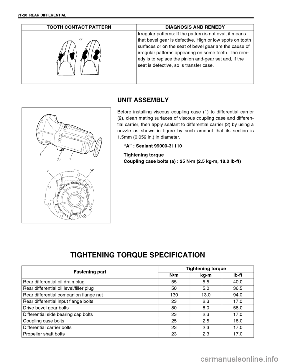
Before installing viscous coupling case (1) to differential carrier
(2), clean mating surfaces of viscous coupling case and differen-
tial carrier, then apply sealant to differential carrier (2) by using a
nozzle as shown in figure by such amount that its section is
1.5mm (0.059 in.) in diameter.
“A” : Sealant 99000-31110
Tightening torque
Coupling case bolts (a) : 25 N·m (2.5 kg-m, 18.0 lb-ft)
TIGHTENING TORQUE SPECIFICATION
Irregular patterns: If the pattern is not oval, it means
that bevel gear is defective. High or low spots on tooth
surfaces or on the seat of bevel gear are the cause of
irregular patterns appearing on some teeth. The rem-
edy is to replace the pinion and-gear set and, if the
seat is defective, so is transfer case. TOOTH CONTACT PATTERN DIAGNOSIS AND REMEDY
Fastening partTightening torque
Nm kg-m lb-ft
Rear differential oil drain plug 55 5.5 40.0
Rear differential oil level/filler plug 50 5.0 36.5
Rear differential companion flange nut 130 13.0 94.0
Rear differential input flange bolts 23 2.3 17.0
Drive bevel gear bolts 80 8.0 58.0
Differential side bearing cap bolts 23 2.3 17.0
Coupling case bolts 25 2.5 18.0
Differential carrier bolts 23 2.3 17.0
Propeller shaft bolts 23 2.3 17.0