2000 SUZUKI SWIFT oil
[x] Cancel search: oilPage 293 of 447
IMMOBILIZER CONTROL SYSTEM 8G-15
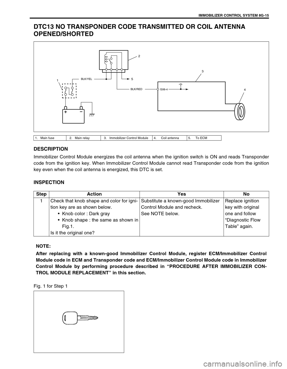
DTC13 NO TRANSPONDER CODE TRANSMITTED OR COIL ANTENNA
OPENED/SHORTED
DESCRIPTION
Immobilizer Control Module energizes the coil antenna when the ignition switch is ON and reads Transponder
code from the ignition key. When Immobilizer Control Module cannot read Transponder code from the ignition
key even when the coil antenna is energized, this DTC is set.
INSPECTION
Fig. 1 for Step 1
1. Main fuse 2. Main relay 3. Immobilizer Control Module 4. Coil antenna 5. To ECM
BLK/RED
BLK/YEL
G06-4
2
3
4 5
1
Step Action Yes No
1 Check that knob shape and color for igni-
tion key are as shown below.
Knob color : Dark gray
Knob shape : the same as shown in
Fig.1.
Is it the original one?Substitute a known-good Immobilizer
Control Module and recheck.
See NOTE below.Replace ignition
key with original
one and follow
“Diagnostic Flow
Table” again.
NOTE:
After replacing with a known-good Immobilizer Control Module, register ECM/Immobilizer Control
Module code in ECM and Transponder code and ECM/Immobilizer Control Module code in Immobilizer
Control Module by performing procedure described in “PROCEDURE AFTER IMMOBILIZER CON-
TROL MODULE REPLACEMENT” in this section.
Page 317 of 447
BODY SERVICE 9-13
REMOVAL
1) Clean both inside and outside of glass and around it.
2) Remove wiper arms and garnish.
3) Using tape, cover body surface around glass to prevent any
damage.
4) Remove rear view mirror, sunvisor, and front pillar trims (right
& left).
5) If necessary, remove instrument panel. Refer to “INSTRU-
MENT PANEL” in this section.
6) If necessary, remove head lining. Refer to “HEAD LINING” in
this section.
7) Remove (or cut) windshield molding.
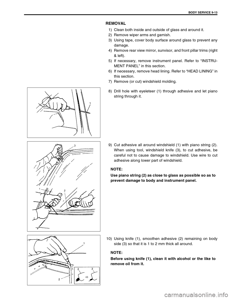
8) Drill hole with eyeleteer (1) through adhesive and let piano
string through it.
9) Cut adhesive all around windshield (1) with piano string (2).
When using tool, windshield knife (3), to cut adhesive, be
careful not to cause damage to windshield. Use wire to cut
adhesive along lower part of windshield.
10) Using knife (1), smoothen adhesive (2) remaining on body
side (3) so that it is 1 to 2 mm thick all around.
NOTE:
Use piano string (2) as close to glass as possible so as to
prevent damage to body and instrument panel.
NOTE:
Before using knife (1), clean it with alcohol or the like to
remove oil from it.
Page 328 of 447
9-24 BODY SERVICE
INSTALLATION
Reverse removal procedure to install back door noting the follow-
ing instructions.
Secure wiring harness.
Adjust door latch striker position by referring “BACK DOOR
LOCK ASSEMBLY” in this section.
Adjust door cushion so that door contacts body when closed.
Adjust door clearance by loosening door hinge mounting
bolts and nuts referring to “PANEL CLEARANCE” in this sec-
tion.
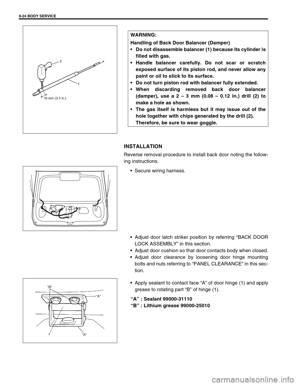
Apply sealant to contact face “A” of door hinge (1) and apply
grease to rotating part “B” of hinge (1).
“A” : Sealant 99000-31110
“B” : Lithium grease 99000-25010 WARNING:
Handling of Back Door Balancer (Damper)
Do not disassemble balancer (1) because its cylinder is
filled with gas.
Handle balancer carefully. Do not scar or scratch
exposed surface of its piston rod, and never allow any
paint or oil to stick to its surface.
Do not turn piston rod with balancer fully extended.
When discarding removed back door balancer
(damper), use a 2 – 3 mm (0.08 – 0.12 in.) drill (2) to
make a hole as shown.
The gas itself is harmless but it may issue out of the
hole together with chips generated by the drill (2).
Therefore, be sure to wear goggle.
Page 336 of 447
![SUZUKI SWIFT 2000 1.G Transmission Service Workshop Manual 9-32 BODY SERVICE
Hole to hole distance
[B] : 5 door model f. Side sill scuff installation rear hole l. Rear door rear notch
a. Front door upper hinge installation hole g. Front shoulder adjuster inst SUZUKI SWIFT 2000 1.G Transmission Service Workshop Manual 9-32 BODY SERVICE
Hole to hole distance
[B] : 5 door model f. Side sill scuff installation rear hole l. Rear door rear notch
a. Front door upper hinge installation hole g. Front shoulder adjuster inst](/manual-img/20/7605/w960_7605-335.png)
9-32 BODY SERVICE
Hole to hole distance
[B] : 5 door model f. Side sill scuff installation rear hole l. Rear door rear notch
a. Front door upper hinge installation hole g. Front shoulder adjuster installation upper
holem. Rear door switch installation hole
b. Front door lower hinge installation hole h. Rear door upper hinge installation hole n. Side soil scuff installation rear hole
c. Front pillar inner trim installation lower hole i. Front door switch installation hole o. Parking brake cable bracket installation rear
hole
d. Front pillar inner trim installation upper hole j. Rear door lower hinge installation hole p. Steering support member installation hole
e. Assistant grip installation front hole k. Assistant grip installation hole
a-g : 1166 mm (45.90 in.) d-i : 820 mm (32.28 in.) i-o : 742 mm (29.21 in.)
a-h : 942 mm (37.09 in.) d-o : 1252 mm (49.29 in.) j-m : 895 mm (35.24 in.)
a-i : 901 mm (35.47 in.) e- f : 1077 mm (42.40 in.) k-n : 1089 mm (42.87 in.)
b-i : 891 mm (35.08 in.) e-o : 1244 mm (48.98 in.) k-o : 1321 mm (52.01 in.)
b-j : 902 mm (35.51 in.) f-g: 1048 mm (41.26 in.) l-n : 948 mm (37.32 in.)
b-o : 1222 mm (48.11 in.) f-o 785 mm (30.91 in.) l-o : 1323 mm (52.09 in.)
c-f : 884 mm (34.80 in.) g-l : 621 mm (24.45 in.) m-o : 1111 mm (43.74 in.)
c-o: 1282 mm (50.47 in.) g-o : 1147 mm (45.16 in.) n-o : 813 mm (32.00 in.)
d-f : 993 mm (39.09 in.) h-l : 846 mm (33.31 in.) o-p : 1229 mm (48.39 in.)
d-g : 580 mm (22.83 in.) h-m : 813 mm (32.01 in.)
a
c
gd
ek
l
m
n
i
h
bf
j
a
c
dl
k
g
e
n
m
i
f
b o
o [B]
Page 376 of 447
10B-2 AIR BAG SYSTEM
DTC B1025 – DRIVER AIR BAG
INITIATOR CIRCUIT SHORT TO POWER
CIRCUIT ................................................... 10B-29
DTC B1032 – POWER SOURCE
VOLTAGE LOW ........................................ 10B-36
DTC B1041 – DRIVER PRETENSIONER
INITIATOR CIRCUIT RESISTANCE
HIGH ......................................................... 10B-38
DTC B1042 – DRIVER PRETENSIONER
INITIATOR CIRCUIT RESISTANCE
LOW .......................................................... 10B-38
DTC B1043 – DRIVER PRETENSIONER
INITIATOR CIRCUIT SHORT TO
GROUND .................................................. 10B-38
DTC B1044 – DRIVER PRETENSIONER
INITIATOR CIRCUIT SHORT TO
POWER CIRCUIT ..................................... 10B-38
DTC B1045 – PASSENGER
PRETENSIONER INITIATOR CIRCUIT
RESISTANCE HIGH ................................. 10B-38
DTC B1046 – PASSENGER
PRETENSIONER INITIATOR CIRCUIT
RESISTANCE LOW .................................. 10B-38
DTC B1047 – PASSENGER
PRETENSIONER INITIATOR CIRCUIT
SHORT TO GROUND .............................. 10B-38
DTC B1048 – PASSENGER
PRETENSIONER INITIATOR CIRCUIT
SHORT TO POWER CIRCUIT ................. 10B-38
DTC B1051 – FRONTAL CRASH
DETECTED (SYSTEM ACTIVATION
COMMAND OUTPUTTED) ....................... 10B-44
DTC B1071 - INTERNAL SDM FAULT ..... 10B-45
DTC B1013 – SYSTEM
SPECIFICATIONS DIFFERENT FROM SDM SPECIFICATIONS ........................... 10B-45
ON-VEHICLE SERVICE............................... 10B-46
SERVICE PRECAUTIONS ....................... 10B-46
SERVICE AND DIAGNOSIS................. 10B-46
DISABLING AIR BAG SYSTEM ........... 10B-47
ENABLING AIR BAG SYSTEM ............ 10B-47
HANDLING AND STORAGE ................ 10B-48
REPAIRS AND INSPECTIONS
REQUIRED AFTER AN ACCIDENT......... 10B-53
ACCIDENT WITH DEPLOYMENT/
ACTIVATION - COMPONENT
REPLACEMENT ....................................... 10B-53
ACCIDENT WITH OR WITHOUT
DEPLOYMENT/ACTIVATION -
COMPONENT INSPECTIONS ................. 10B-53
SDM .......................................................... 10B-56
DRIVER AIR BAG (INFLATOR)
MODULE .................................................. 10B-59
CONTACT COIL AND COMBINATION
SWITCH ASSEMBLY ............................... 10B-59
SEAT BELT PRETENSIONER (IF
EQUIPPED) .............................................. 10B-59
AIR BAG (INFLATOR) MODULE AND
SEAT BELT PRETENSIONER
DISPOSAL ................................................... 10B-60
DEPLOYMENT/ACTIVATION OUTSIDE
VEHICLE .................................................. 10B-61
DEPLOYMENT/ACTIVATION INSIDE
VEHICLE .................................................. 10B-67
DEPLOYED AIR BAG (INFLATOR)
MODULE AND ACTIVATED SEAT BELT
PRETENSIONER DISPOSAL .................. 10B-70
SPECIAL TOOL ........................................... 10B-71
Page 378 of 447

10B-4 AIR BAG SYSTEM
SYSTEM COMPONENTS AND WIRING LOCATION VIEW AND CONNECTORS
1. Air bag harness 6. Passenger air bag (inflator) module
2.“Air bag” monitor coupler 7. SDM
3. DLC 8. Seat belt pretensioner (retractor assembly) (if equipped)
4. Contact coil assembly 9. Ground for air bag system
5. Driver air bag (inflator) module
CONNECTOR “Q02”CONNECTOR “G39”
146
9
5
7
8 3
8
“Q06”
Page 379 of 447
AIR BAG SYSTEM 10B-5
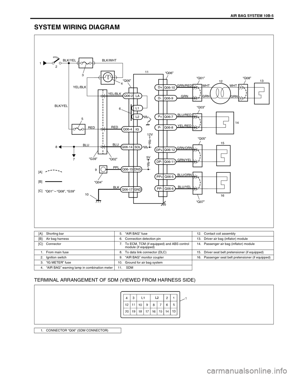
SYSTEM WIRING DIAGRAM
TERMINAL ARRANGEMENT OF SDM (VIEWED FROM HARNESS SIDE)
1
2
3
4 BLK/YEL
BLK/YELBLK/WHT
YEL/BLK
YEL/BLKGRN/RED
GRN GRNWHT WHT
GRN
BLU/RED
YEL/RED
GRN/ORN
GRN/YEL
BLU/ORN
BLU/YEL
6
12V
5V REDRED
BLU
BLU
5
8
7“G39”
“Q02”
“Q07” “Q05”
9
10PPL
BLK
“Q04”
Q06-2
Q06-4
Q06-14Q06-7
Q06-8 Q06-10
Q06-9
Q06-12
Q06-11
Q06-5
Q06-6 Q06-15
Q06-17L1
L2
IG
SDL
DNS
GNDLA
PP- PP+ DP- DP+P- P+ D- D+
“Q03”
“Q01”
“Q06”
“Q08”
15
161413
12 11
[A]
[B]
[C]
“Q01” “Q08”, “G39”
“Q06”
[A]: Shorting bar 5.“AIR BAG” fuse 12. Contact coil assembly
[B]: Air bag harness 6. Connection detection pin 13. Driver air bag (inflator) module
[C]: Connector 7. To ECM, TCM (if equipped) and ABS control
module (if equipped) 14. Passenger air bag (inflator) module
1. From main fuse 8. To data link connector (DLC) 15. Driver seat belt pretensioner (if equipped)
2. Ignition switch 9.“AIR BAG” monitor coupler 16. Passenger seat belt pretensioner (if equipped)
3.“IG METER” fuse 10. Ground for air bag system
4.“AIR BAG” warning lamp in combination meter 11. SDM
1. CONNECTOR “Q06” (SDM CONNECTOR)
Page 381 of 447
AIR BAG SYSTEM 10B-7
The adapter will also give an idea of whether contact tension is
sufficient, helping to find an open or intermittent open due to poor
terminal contact.
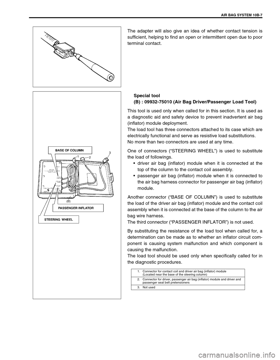
Special tool
(B) : 09932-75010 (Air Bag Driver/Passenger Load Tool)
This tool is used only when called for in this section. It is used as
a diagnostic aid and safety device to prevent inadvertent air bag
(inflator) module deployment.
The load tool has three connectors attached to its case which are
electrically functional and serve as resistive load substitutions.
No more than two connectors are used at any time.
One of connectors (“STEERING WHEEL”) is used to substitute
the load of followings.
driver air bag (inflator) module when it is connected at the
top of the column to the contact coil assembly.
passenger air bag (inflator) module when it is connected to
the air bag harness connector for passenger air bag (inflator)
module.
Another connector (“BASE OF COLUMN”) is used to substitute
the load of the driver air bag (inflator) module and the contact coil
assembly when it is connected at the base of the column to the air
bag wire harness.
The third connector (“PASSENGER INFLATOR”) is not used.
By substituting the resistance of the load tool when called for, a
determination can be made as to whether an inflator circuit com-
ponent is causing system malfunction and which component is
causing the malfunction.
The load tool should be used only when specifically called for in
the diagnostic procedures.
1. Connector for contact coil and driver air bag (inflator) module
(Located near the base of the steering column)
2. Connector for driver, passenger air bag (inflator) module and driver and
passenger seat belt pretensioners
3. Not used