Page 527 of 557

1. Solenoid valve wire coupler (Disconnected)
2. Transmission
7B-36 AUTOMATIC TRANSMISSION (3 A / T) (VEHICLE WITH WU-TWC)
MANUAL ROAD TEST
This test checks the gears being used in L, 2 or D range when driven
with unoperated gear shift control system.
Test drive vehicle on a level road.
1) With selector lever in P range, start engine and warm it up.
2) After warming up engine, disconnect coupler of solenoid valve
wire as shown in left figure.
3) With selector lever in L range, start vehicle and accelerate to
30 km / h (19 mile / h). Check in this state that 1st gear is being
used.
4) At 30 km / h (19 mile / h), shift selector lever to 2 range and accel-
erate to 60 km / h (37 mile / h).
Check in this state that 2nd gear is being used.
5) At 60 km / h (37 mile / h), shift selector lever to D range and check
that 3rd gear is used when speed is higher than 60 km / h
(37 mile / h).
6) After above checks, stop vehicle then engine, and connect sole-
noid valve wire coupler.
ENGINE BRAKE TEST
WARNING:
Before test, make sure that there is no vehicle behind so as
to prevent rear-end collision.
1) While driving vehicle in 3rd gear of D range, shift selector lever
down to 2 range and check if engine brake operates.
2) In the same way as in step 1), check engine brake for operation
when selector lever is shifted down to L range.
3) If engine brake fails to operate in above tests, possible cause for
such failure are as follows.
Check each part which is suspected to be the cause.
Condition
Possible causes
Fails to operate when
shifted down to 2 rangeSecond brake defective
Fails to operate when
shifted down to L range1st-reverse brake defective
Page 528 of 557

WITHOUT BATTERY VOLTAGE
WITH BATTERY VOLTAGE
1. Oiler (with transmission fluid)
2. Solenoid valve
3. 12V battery
“A”: Side hole (Should be dry)
“B”: Exhausting fluid
AUTOMATIC TRANSMISSION (3 A / T) (VEHICLE WITH WU-TWC) 7B-37
“P” RANGE TEST
1) Stop vehicle on a slope, shift selector lever to P range and at the
same time apply parking brake.
2) After stopping engine, release parking brake lever gradually and
check that vehicle remains stationary.
SHIFT SOLENOID VALVE CHECK
Whenever shift solenoid valves are removed from transmission,
verify their valve function physically before they are reinstalled.
1) Apply oiler to solenoid valve and give compression by hands
and then check to be sure that transmission fluid from oiler does
not come out from side holes of solenoid valve when battery volt-
age is not conducted.
2) Holding the above condition, conduct battery voltage and then
make sure that fluid is exhausted with vigor.
NOTE:
If fluid does not come out with vigor in above step 2) inspec-
tion, do not reuse that solenoid valve.
Page 529 of 557

7B-38 AUTOMATIC TRANSMISSION (3 A / T) (VEHICLE WITH WU-TWC)
TABLE B-1 GEAR SHIFT FAILURE IN “D” OR “2” RANGE
STEPACTIONYESNO
1Was “TABLE A-2 GEAR CHANGE FAILURE” performed?Go to Step 2.Go to “TABLE
A-2”.
2Is gear no shift at all?Go to Step 3.Go to Step 4.
3Perform vehicle speed sensor check refer to “OUTPUT
SPEED SENSOR CHECK” in this section.
Is check result satisfactory?Go to Step 5.Repair or
replace.
4Perform throttle position sensor check referring to DTC P0121
Flow Table in Section 6-1.
Is check result satisfactory?Go to Step 5.Repair or
replace.
5Perform “SHIFT SOLENOID VALVE CIRCUIT CHECK”
described later in this section.
Is check result satisfactory?Substitute a
known-good
PCM and
recheck.Replace shift
solenoid-A
(direct clutch
solenoid) valve
or shift
solenoid-B (2nd
brake solenoid)
valve.
TABLE B-2 GEAR IS SHIFTED TO 2ND GEAR IN “L” RANGE
VEHICLE DOES NOT MOVE BACKWARD IN “R” RANGE
NOTE:
Gear shift to 2nd may occur when selector lever is shifted from D or 2 to L, but this is normal.
STEP
ACTIONYESNO
1Was “TABLE A-2 GEAR CHANGE FAILURE” performed?Go to Step 2.Go to “TABLE
A-2”.
2Perform “SHIFT SOLENOID VALVE CIRCUIT CHECK”
described later in this section.
Is check result satisfactory?Substitute a
known-good
PCM and
recheck.Replace shift
solenoid-A
(direct clutch
solenoid) valve
or shift
solenoid-B (2nd
brake solenoid)
valve.
Page 531 of 557

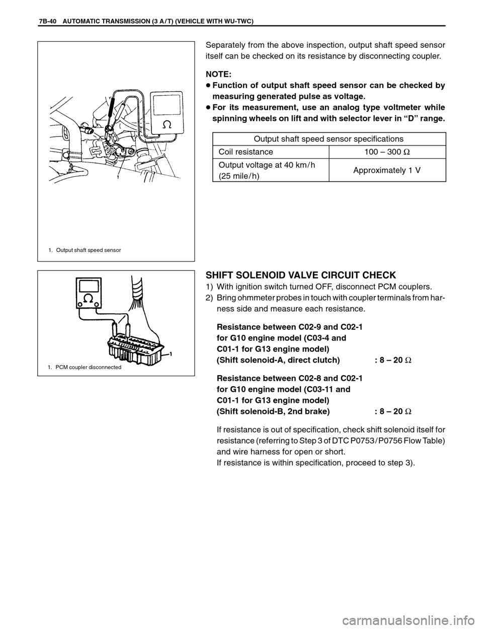
1. Output shaft speed sensor
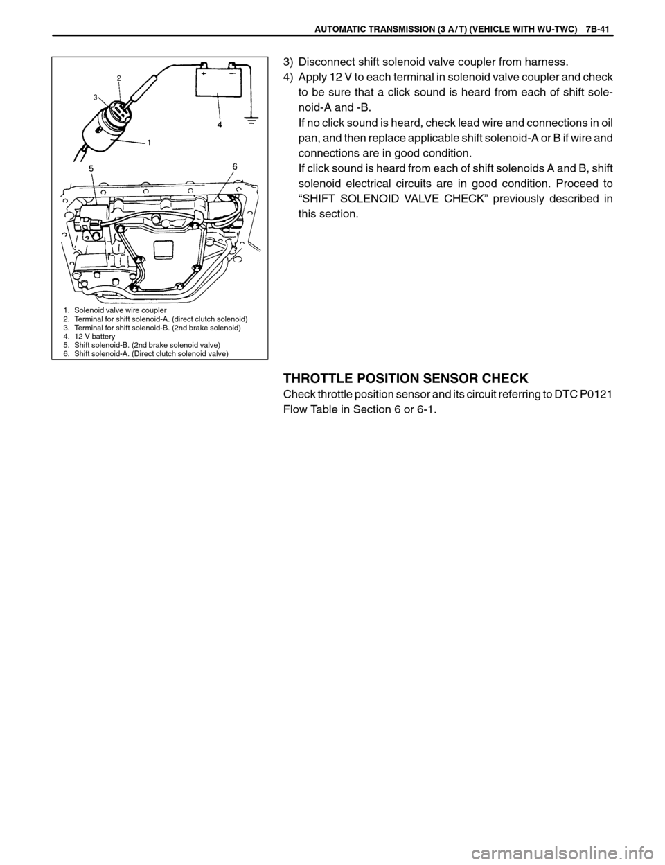
1. PCM coupler disconnected
7B-40 AUTOMATIC TRANSMISSION (3 A / T) (VEHICLE WITH WU-TWC)
Separately from the above inspection, output shaft speed sensor
itself can be checked on its resistance by disconnecting coupler.
NOTE:
�Function of output shaft speed sensor can be checked by
measuring generated pulse as voltage.
�For its measurement, use an analog type voltmeter while
spinning wheels on lift and with selector lever in “D” range.
Output shaft speed sensor specifications
Coil resistance100 – 300 Ω
Output voltage at 40 km / h
(25 mile / h)Approximately 1 V
SHIFT SOLENOID VALVE CIRCUIT CHECK
1) With ignition switch turned OFF, disconnect PCM couplers.
2) Bring ohmmeter probes in touch with coupler terminals from har-
ness side and measure each resistance.
Resistance between C02-9 and C02-1
for G10 engine model (C03-4 and
C01-1 for G13 engine model)
(Shift solenoid-A, direct clutch) : 8 – 20 Ω
Resistance between C02-8 and C02-1
for G10 engine model (C03-11 and
C01-1 for G13 engine model)
(Shift solenoid-B, 2nd brake) : 8 – 20 Ω
If resistance is out of specification, check shift solenoid itself for
resistance (referring to Step 3 of DTC P0753 / P0756 Flow Table)
and wire harness for open or short.
If resistance is within specification, proceed to step 3).
Page 532 of 557

1. Solenoid valve wire coupler
2. Terminal for shift solenoid-A. (direct clutch solenoid)
3. Terminal for shift solenoid-B. (2nd brake solenoid)
4. 12 V battery
5. Shift solenoid-B. (2nd brake solenoid valve)
6. Shift solenoid-A. (Direct clutch solenoid valve)
AUTOMATIC TRANSMISSION (3 A / T) (VEHICLE WITH WU-TWC) 7B-41
3) Disconnect shift solenoid valve coupler from harness.
4) Apply 12 V to each terminal in solenoid valve coupler and check
to be sure that a click sound is heard from each of shift sole-
noid-A and -B.
If no click sound is heard, check lead wire and connections in oil
pan, and then replace applicable shift solenoid-A or B if wire and
connections are in good condition.
If click sound is heard from each of shift solenoids A and B, shift
solenoid electrical circuits are in good condition. Proceed to
“SHIFT SOLENOID VALVE CHECK” previously described in
this section.
THROTTLE POSITION SENSOR CHECK
Check throttle position sensor and its circuit referring to DTC P0121
Flow Table in Section 6 or 6-1.
Page 535 of 557
NOTE:
Terminal arrangement of coupler viewed from harness side.
Coupler A
1. To generator W / R
2. To ignition switch B / W
3. To ECM V / G
4. To ECM V
5. Blank –
6. To ECT sensor Y / W
7. Blank —
8. To engine oil pressure switch Y / B
9. To ECM Br
10. Blank —
11. To SDM (if equipped) Bl
12. Blank —
13. Blank —
14. Blank —
15. To ground R
16. To combination switch R / Y
Coupler B
1. To combination switch G / R
2. Blank —
3. Blank —
4. To ECM Y / G
5. To brake fluid level switch and R / B
parking brake switch
6. Blank —
7. To ABS control module R / Bl
(if equipped)
8. Blank —
9. To fuel level gauge Y / R
10. To ground B / Bl
11. To ignition switch B / W
12. Blank —
13. Blank —
Coupler C
1. Blank —
2. Blank —
3. Blank —
4. Blank —
5. Blank —
6. Blank —
7. To main fuse R
8. To combination switch W / Bl
9. To ground B
10. To combination switch G / Y
Coupler A Coupler B Coupler C
8-2 BODY ELECTRICAL SYSTEM
GENERAL DESCRIPTION
COMBINATION METER