Page 6 of 698

GENERAL INFORMATION 0A-3
PRECAUTIONS
PRECAUTION FOR VEHICLES EQUIPPED
WITH A SUPPLEMENTAL RESTRAINT
(AIR BAG) SYSTEM
DIAGNOSIS
When troubleshooting air bag system, be sure to follow
“DIAGNOSIS” in SECTION 10B. Bypassing these proce-
dures may result in extended diagnostic time, incorrect diag-
nosis, and incorrect parts replacement.
Never use electrical test equipment other than that specified
in this manual. WARNING:
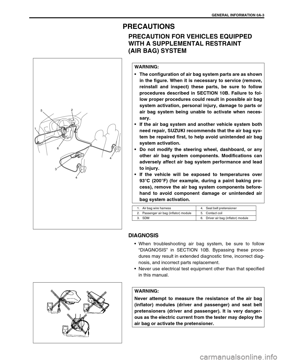
The configuration of air bag system parts are as shown
in the figure. When it is necessary to service (remove,
reinstall and inspect) these parts, be sure to follow
procedures described in SECTION 10B. Failure to fol-
low proper procedures could result in possible air bag
system activation, personal injury, damage to parts or
air bag system being unable to activate when neces-
sary.
If the air bag system and another vehicle system both
need repair, SUZUKI recommends that the air bag sys-
tem be repaired first, to help avoid unintended air bag
system activation.
Do not modify the steering wheel, dashboard, or any
other air bag system components. Modifications can
adversely affect air bag system performance and lead
to injury.
If the vehicle will be exposed to temperatures over
93°C (200°F) (for example, during a paint baking pro-
cess), remove the air bag system components before-
hand to avoid component damage or unintended air
bag system activation.
1. Air bag wire harness 4. Seat belt pretensioner
2. Passenger air bag (inflator) module 5. Contact coil
3. SDM 6. Driver air bag (inflator) module
3
4
4
6
1
52
WARNING:
Never attempt to measure the resistance of the air bag
(inflator) modules (driver and passenger) and seat belt
pretensioners (driver and passenger). It is very danger-
ous as the electric current from the tester may deploy the
air bag or activate the pretensioner.
Page 21 of 698
0A-18 GENERAL INFORMATION
IDENTIFICATION INFORMATION
VEHICLE IDENTIFICATION NUMBER
The number is punched on front dash panel in engine room.
ENGINE IDENTIFICATION NUMBER
The number is punched on cylinder block.
TRANSMISSION IDENTIFICATION NUMBER
The automatic transmission identification number is located on
transmission case.
Page 63 of 698
1A-12 HEATER AND VENTILATION
AIR INLET BOX
REMOVAL
1) Disconnect negative (–) cable at battery.
2) Remove glove box.
3) Disable air bag system by referring to “DISABLING AIR BAG
SYSTEM” in Section 10B. (if equipped)
4) Disconnect fresh air control cable (1) from air inlet box.
1. Resistance board 4. Fresh air duct packing 7. Air inlet door 10. Cable clamp
2. Air inlet case
: Apply sealant 99000 - 31160 to hatched part “A”
5. Door link 8. Clip : Do not reuse
3. Fresh air duct case 6. Heater unit packing 9. Dash packing
NOTE:
If vehicle equipped with A/C, refer to “COOLING UNIT” in
Section 1B.
1
72
8 1053
“A”
2
4
6
9
Page 97 of 698
1B-32 AIR CONDITIONING (OPTIONAL)
COOLING UNIT (EVAPORATOR)
REMOVAL
1) Disconnect negative (–) cable at battery.
2) Recover refrigerant from A/C system by referring to
“RECOVERY” in this section.
3) Remove glove box.
1. A/C evaporator 6. Dash packing 11. O-ring
2. A/C evaporator temperature sensor 7. Packing 12. Door link
3. Expansion valve 8. Fresh air duct case 13. Lower packing
4. Evaporator case
: Apply sealant 99000-31160 to hatched part “A”.9. Clamp Do not reuse.
5. Cooling unit packing 10. Air inlet door
CAUTION:
Be careful not to damage A/C evaporator fins. If A/C
evaporator fin is bent, straighten it by using flat head
screwdriver or pair of pliers.
NOTE:
The amount of removed compressor oil must be mea-
sured for replenishing compressor oil.
Page 281 of 698

5-8 BRAKES
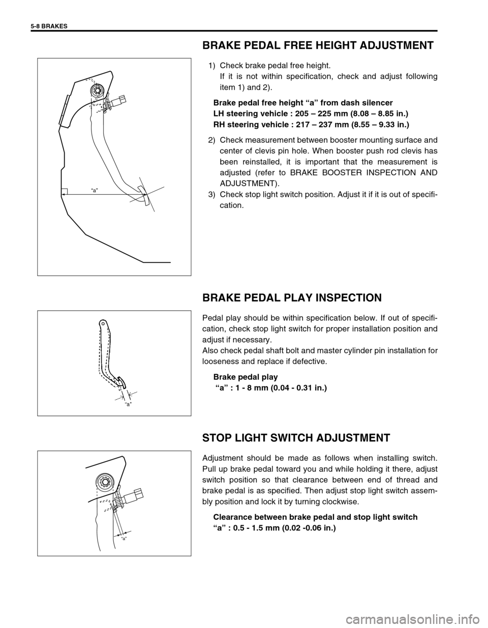
BRAKE PEDAL FREE HEIGHT ADJUSTMENT
1) Check brake pedal free height.
If it is not within specification, check and adjust following
item 1) and 2).
Brake pedal free height “a” from dash silencer
LH steering vehicle : 205 – 225 mm (8.08 – 8.85 in.)
RH steering vehicle : 217 – 237 mm (8.55 – 9.33 in.)
2) Check measurement between booster mounting surface and
center of clevis pin hole. When booster push rod clevis has
been reinstalled, it is important that the measurement is
adjusted (refer to BRAKE BOOSTER INSPECTION AND
ADJUSTMENT).
3) Check stop light switch position. Adjust it if it is out of specifi-
cation.
BRAKE PEDAL PLAY INSPECTION
Pedal play should be within specification below. If out of specifi-
cation, check stop light switch for proper installation position and
adjust if necessary.
Also check pedal shaft bolt and master cylinder pin installation for
looseness and replace if defective.
Brake pedal play
“a” : 1 - 8 mm (0.04 - 0.31 in.)
STOP LIGHT SWITCH ADJUSTMENT
Adjustment should be made as follows when installing switch.
Pull up brake pedal toward you and while holding it there, adjust
switch position so that clearance between end of thread and
brake pedal is as specified. Then adjust stop light switch assem-
bly position and lock it by turning clockwise.
Clearance between brake pedal and stop light switch
“a” : 0.5 - 1.5 mm (0.02 -0.06 in.)
“a”
“a”
Page 282 of 698

BRAKES 5-9
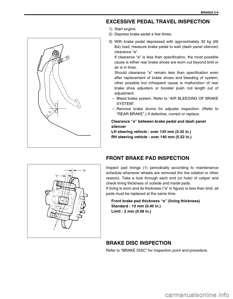
EXCESSIVE PEDAL TRAVEL INSPECTION
1) Start engine.
2) Depress brake pedal a few times.
3) With brake pedal depressed with approximately 30 kg (66
lbs) load, measure brake pedal to wall (dash panel silencer)
clearance “a”.
If clearance “a” is less than specification, the most possible
cause is either rear brake shoes are worn out beyond limit or
air is in lines.
Should clearance “a” remain less than specification even
after replacement of brake shoes and bleeding of system,
other possible but infrequent cause is malfunction of rear
brake shoe adjusters or booster push rod length out of
adjustment.
–Bleed brake system. Refer to “AIR BLEEDING OF BRAKE
SYSTEM”.
–Remove brake drums for adjuster inspection. (Refer to
“REAR BRAKE”.) If defective, correct or replace.
Clearance “a” between brake pedal and dash panel
silencer
LH steering vehicle : over 135 mm (5.32 in.)
RH steering vehicle : over 140 mm (5.52 in.)
FRONT BRAKE PAD INSPECTION
Inspect pad linings (1) periodically according to maintenance
schedule whenever wheels are removed (for tire rotation or other
reason). Take a look through each end (or hole) of caliper and
check lining thickness of outside and inside pads.
If lining is worn and its thickness (“a” in figure) is less than limit, all
pads must be replaced at the same time.
Front brake pad thickness “a” (lining thickness)
Standard : 10 mm (0.40 in.)
Limit : 2 mm (0.08 in.)
BRAKE DISC INSPECTION
Refer to “BRAKE DISC” for inspection point and procedure.
“a”
Page 312 of 698

BRAKES 5-39
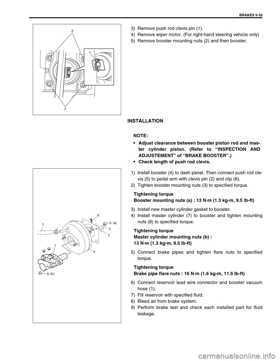
3) Remove push rod clevis pin (1).
4) Remove wiper motor. (For right-hand steering vehicle only)
5) Remove booster mounting nuts (2) and then booster.
INSTALLATION
1) Install booster (4) to dash panel. Then connect push rod cle-
vis (5) to pedal arm with clevis pin (2) and clip (6).
2) Tighten booster mounting nuts (3) to specified torque.
Tightening torque
Booster mounting nuts (a) : 13 N·m (1.3 kg-m, 9.5 lb-ft)
3) Install new master cylinder gasket to booster.
4) Install master cylinder (7) to booster and tighten mounting
nuts (8) to specified torque.
Tightening torque
Master cylinder mounting nuts (b) :
13 N·m (1.3 kg-m, 9.5 lb-ft)
5) Connect brake pipes and tighten flare nuts to specified
torque.
Tightening torque
Brake pipe flare nuts : 16 N·m (1.6 kg-m, 11.5 lb-ft)
6) Connect reservoir lead wire connector and booster vacuum
hose (1).
7) Fill reservoir with specified fluid.
8) Bleed air from brake system.
9) Perform brake test and check each installed part for fluid
leakage.
1
2
2
NOTE:
Adjust clearance between booster piston rod and mas-
ter cylinder piston. (Refer to “INSPECTION AND
ADJUSTEMENT” of “BRAKE BOOSTER”.)
Check length of push rod clevis.