2000 SUZUKI SWIFT brake fluid
[x] Cancel search: brake fluidPage 321 of 698

5-48 BRAKES
LSPV (LOAD SENSING PROPORTIONING VALVE) ASSEMBLY (IF EQUIPPED)
REMOVAL
1) Clean around reservoir cap and take out fluid with syringe or
such.
2) Hoist vehicle.
3) Disconnect brake pipes from LSPV assembly.
Special tool
09950-78230 (10 x 11 mm)
4) Remove nut (2) and detach spring end from rear axle (3).
5) Remove LSPV assembly (1) with spring (4) from vehicle
body.
1. LSPV assembly 3. Adjust nut Tightening torque
2. Spring 4. Brake pipe
CAUTION:
Never disassemble LSPV assembly. Disassembly will
spoil its original performance. Replace with new one if
detective.
3
21
25 N·m(2.5 kg-m)
4 16 N·m(1.6 kg-m)
25 N·m(2.5 kg-m)
3
24
1
Page 322 of 698

BRAKES 5-49
INSTALLATION
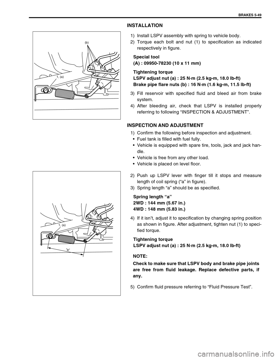
1) Install LSPV assembly with spring to vehicle body.
2) Torque each bolt and nut (1) to specification as indicated
respectively in figure.
Special tool
(A) : 09950-78230 (10 x 11 mm)
Tightening torque
LSPV adjust nut (a) : 25 N·m (2.5 kg-m, 18.0 lb-ft)
Brake pipe flare nuts (b) : 16 N·m (1.6 kg-m, 11.5 lb-ft)
3) Fill reservoir with specified fluid and bleed air from brake
system.
4) After bleeding air, check that LSPV is installed properly
referring to following “INSPECTION & ADJUSTMENT”.
INSPECTION AND ADJUSTMENT
1) Confirm the following before inspection and adjustment.
Fuel tank is filled with fuel fully.
Vehicle is equipped with spare tire, tools, jack and jack han-
dle.
Vehicle is free from any other load.
Vehicle is placed on level floor.
2) Push up LSPV lever with finger till it stops and measure
length of coil spring (“a” in figure).
3) Spring length “a” should be as specified.
Spring length “a”
2WD : 144 mm (5.67 in.)
4WD : 148 mm (5.83 in.)
4) If it isn’t, adjust it to specification by changing spring position
as shown in figure. After adjustment, tighten nut (1) to speci-
fied torque.
Tightening torque
LSPV adjust nut (a) : 25 N·m (2.5 kg-m, 18.0 lb-ft)
5) Confirm fluid pressure referring to “Fluid Pressure Test”.
1, (a)
(b)
NOTE:
Check to make sure that LSPV body and brake pipe joints
are free from fluid leakage. Replace defective parts, if
any.
1, (a)
“a”
Page 323 of 698

5-50 BRAKES
REQUIRED SERVICE MATERIAL
SPECIAL TOOL
MaterialRecommended SUZUKI product
(Part Number)Use
Brake fluid DOT 3 or SAE J1703To fill master cylinder reservoir.
To clean and apply to inner parts of master
cylinder caliper and wheel cylinder when they
are disassembled.
Water tight sealant SEALING COMPOUND 366E
(99000-31090)To apply to mating surfaces of brake back
plate and rear axle (2WD vehicle) or rear
axle housing (4WD vehicle).
To apply to mating surfaces of brake back
plate and parking brake cable.
Lithium grease SUZUKI SUPER GREASE A
(99000-25010)To apply to slide pin of brake caliper carrier.
09900-06106 09900-20606 09900-20701 09942-15510
Snap ring remover Dial gauge Dial gauge chuck Sliding hammer
09943-17912 09951-18220 09952-16020 09952-46010
Brake drum remover
(Front wheel hub
remover)Secondary cup installer
setBooster piston rod
adjusterMaster cylinder attach-
ment
Page 324 of 698

BRAKES 5-51
09950-96010 09956-02310 09950-78230 09952-48320
Booster piston rod gauge Fluid pressure gauge Flare nut wrench
(10 x 11 mm)Pressure gauge attach-
ment
09952-26020
Master cylinder plug
Page 327 of 698

5E-2 ANTILOCK BRAKE SYSTEM (ABS)
DTC C1015 (DTC 15) – G SENSOR
CIRCUIT .................................................... 5E-22
DTC C1021 (DTC 21), DTC C1022
(DTC 22) – RIGHT-FRONT WHEEL
SPEED SENSOR CIRCUIT OR SENSOR
RING .......................................................... 5E-24
DTC C1025 (DTC 25), DTC C1026
(DTC 26) – LEFT-FRONT WHEEL
SPEED SENSOR CIRCUIT OR SENSOR
RING .......................................................... 5E-24
DTC C1031 (DTC 31), DTC C1032
(DTC 32) – RIGHT-REAR WHEEL
SPEED SENSOR CIRCUIT OR SENSOR
RING .......................................................... 5E-24
DTC C1035 (DTC 35), DTC C1036
(DTC 36) – LEFT-REAR WHEEL SPEED
SENSOR CIRCUIT OR SENSOR RING.... 5E-24
DTC C1041 (DTC 41) – RIGHT-FRONT
INLET SOLENOID CIRCUIT...................... 5E-26
DTC C1045 (DTC 45) – LEFT-FRONT
INLET SOLENOID CIRCUIT...................... 5E-26
DTC C1051 (DTC 51) – RIGHT-REAR
INLET SOLENOID CIRCUIT...................... 5E-26
DTC C1055 (DTC 55) – LEFT-REAR
INLET SOLENOID CIRCUIT...................... 5E-26
DTC C1042 (DTC 42) – RIGHT-FRONT
OUTLET SOLENOID CIRCUIT.................. 5E-26
DTC C1046 (DTC 46) – LEFT-FRONT
OUTLET SOLENOID CIRCUIT.................. 5E-26
DTC C1052 (DTC 52) – RIGHT-REAR
OUTLET SOLENOID CIRCUIT.................. 5E-26DTC C1056 (DTC 56) – LEFT-REAR
OUTLET SOLENOID CIRCUIT ................. 5E-26
DTC C1057 (DTC 57) – POWER
SOURCE CIRCUIT .................................... 5E-27
DTC C1061 (DTC 61) – ABS PUMP
MOTOR CIRCUIT ...................................... 5E-28
DTC C1063 (DTC 63) – ABS FAIL-SAFE
RELAY CIRCUIT ....................................... 5E-29
DTC C1071 (DTC 71) – ABS CONTROL
MODULE ................................................... 5E-30
ON-VEHICLE SERVICE................................ 5E-31
PRECAUTIONS ......................................... 5E-31
ABS HYDRAULIC UNIT OPERATION
CHECK (USING SUZUKI SCAN TOOL) ... 5E-31
ABS HYDRAULIC UNIT OPERATION
CHECK (NOT USING SUZUKI SCAN
TOOL) ........................................................ 5E-31
ABS HYDRAULIC UNIT/CONTROL
MODULE ASSEMBLY ............................... 5E-33
FRONT WHEEL SPEED SENSOR ........... 5E-35
FRONT WHEEL SPEED SENSOR
RING .......................................................... 5E-37
REAR WHEEL SPEED SENSOR.............. 5E-38
REAR WHEEL SPEED SENSOR
RING (FOR 2WD VEHICLE) ..................... 5E-41
REAR WHEEL SPEED SENSOR
RING(FOR 4WD VEHICLE) ...................... 5E-42
G SENSOR (FOR 4WD VEHICLE
ONLY) ........................................................ 5E-43
SPECIAL TOOL ............................................ 5E-44
GENERAL DESCRIPTION
COMPONENTS/PARTS LOCATION AND BRAKE HOSE/PIPE ROUTING
The ABS (Antilock Brake System) controls the fluid pressure applied to the Wheel cylinder of each brake from
the master cylinder so that each wheel is not locked even when hard braking is applied.
This ABS has also the following function.
While braking is applied, but before ABS control becomes effective, braking force is distributed between the front
and rear so as to prevent the rear wheels from being locked too early for better stability of the vehicle.
Page 328 of 698

ANTILOCK BRAKE SYSTEM (ABS) 5E-3
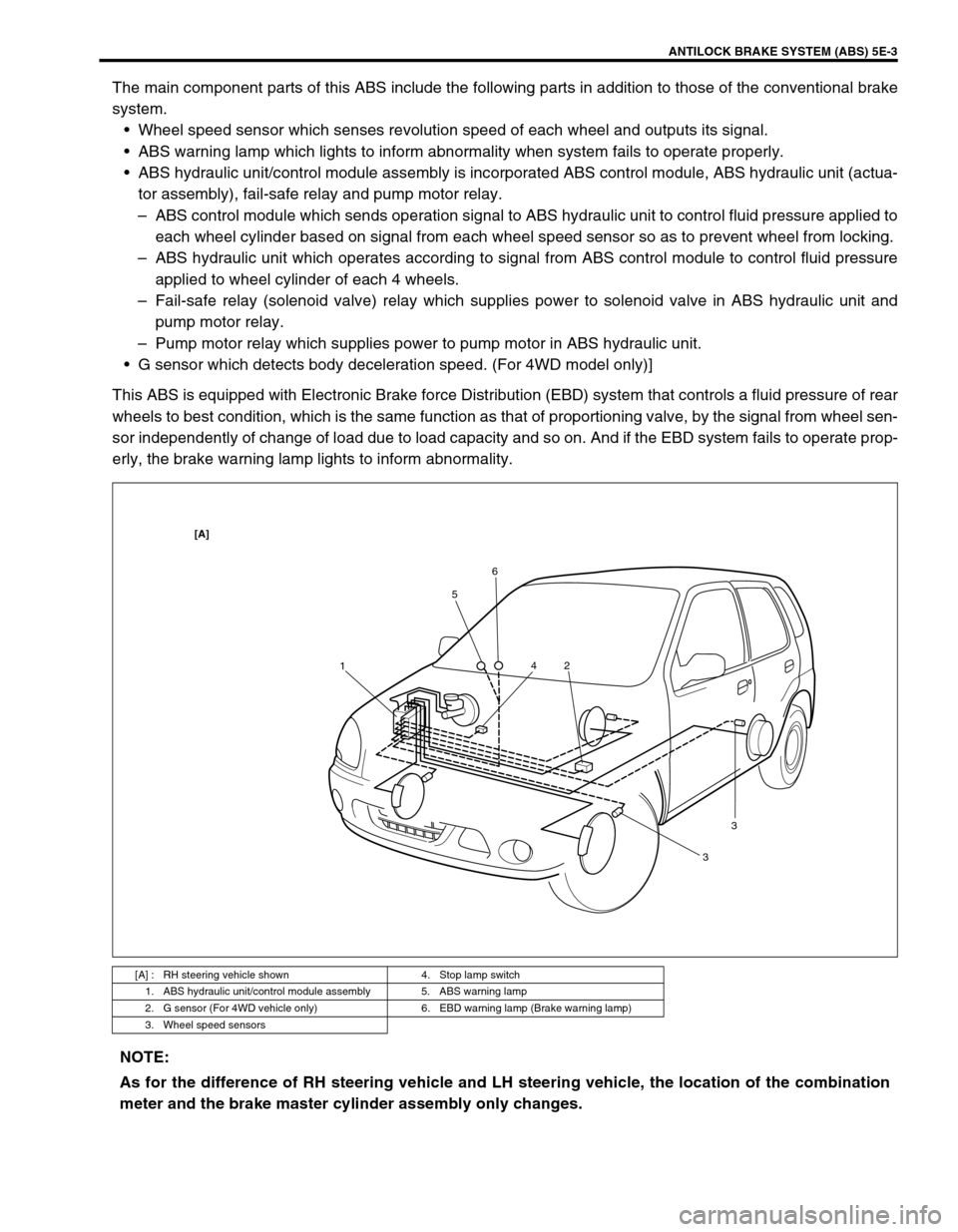
The main component parts of this ABS include the following parts in addition to those of the conventional brake
system.
Wheel speed sensor which senses revolution speed of each wheel and outputs its signal.
ABS warning lamp which lights to inform abnormality when system fails to operate properly.
ABS hydraulic unit/control module assembly is incorporated ABS control module, ABS hydraulic unit (actua-
tor assembly), fail-safe relay and pump motor relay.
–ABS control module which sends operation signal to ABS hydraulic unit to control fluid pressure applied to
each wheel cylinder based on signal from each wheel speed sensor so as to prevent wheel from locking.
–ABS hydraulic unit which operates according to signal from ABS control module to control fluid pressure
applied to wheel cylinder of each 4 wheels.
–Fail-safe relay (solenoid valve) relay which supplies power to solenoid valve in ABS hydraulic unit and
pump motor relay.
–Pump motor relay which supplies power to pump motor in ABS hydraulic unit.
G sensor which detects body deceleration speed. (For 4WD model only)]
This ABS is equipped with Electronic Brake force Distribution (EBD) system that controls a fluid pressure of rear
wheels to best condition, which is the same function as that of proportioning valve, by the signal from wheel sen-
sor independently of change of load due to load capacity and so on. And if the EBD system fails to operate prop-
erly, the brake warning lamp lights to inform abnormality.
[A] : RH steering vehicle shown 4. Stop lamp switch
1. ABS hydraulic unit/control module assembly 5. ABS warning lamp
2. G sensor (For 4WD vehicle only) 6. EBD warning lamp (Brake warning lamp)
3. Wheel speed sensors
156
2 4
33
[A]
NOTE:
As for the difference of RH steering vehicle and LH steering vehicle, the location of the combination
meter and the brake master cylinder assembly only changes.
Page 338 of 698

ANTILOCK BRAKE SYSTEM (ABS) 5E-13
TABLE – A ABS WARNING LAMP CIRCUIT CHECK – LAMP DOES NOT COME
“ON” AT IGNITION SWITCH ON
CIRCUIT DESCRIPTION
Operation (ON/OFF) of ABS warning lamp is controlled by ABS control module through lamp driver module in
combination meter.
If the Antilock brake system is in good condition, ABS control module turns ABS warning lamp ON at the ignition
switch ON, keeps it ON for 2 seconds and then turns it OFF. If an abnormality in the system is detected, ABS
warning lamp is turned ON continuously by ABS control module. Also, it is turned ON continuously by lamp
driver module when the connector of ABS control module is disconnected.
INSPECTION
1. Main fuse 5. ABS warning lamp 9. Brake fluid level switch
2. Ignition switch 6. Brake warning lamp 10. ABS hydraulic unit/control module assembly
3. Circuit fuse 7. Lamp driver module 11. ABS hydraulic unit/control module connector
4. Combination meter 8. Parking brake switch
Step Action Yes No
1 1) Turn ignition switch ON.
Do other warning lamp come ON?Go to Step 2. Go to Step 4.
2 1) Disconnect ABS hydraulic unit/control mod-
ule connector.
Does ABS warning lamp light with ignition
switch ON?Substitute a known-good ABS
hydraulic unit/control module
assembly and recheck.Go to Step 3.
3 1) Remove combination meter.
Is bulb of ABS warning lamp in good condition?“RED/BLU” circuit shorted to
ground. If OK, replace combina-
tion meter (lamp driver module).Replace bulb.
4 Is IG fuse in good condition? Open in “BLK/WHT” wire to
combination meter or poor con-
nection.Repair and replace.
Page 342 of 698

ANTILOCK BRAKE SYSTEM (ABS) 5E-17
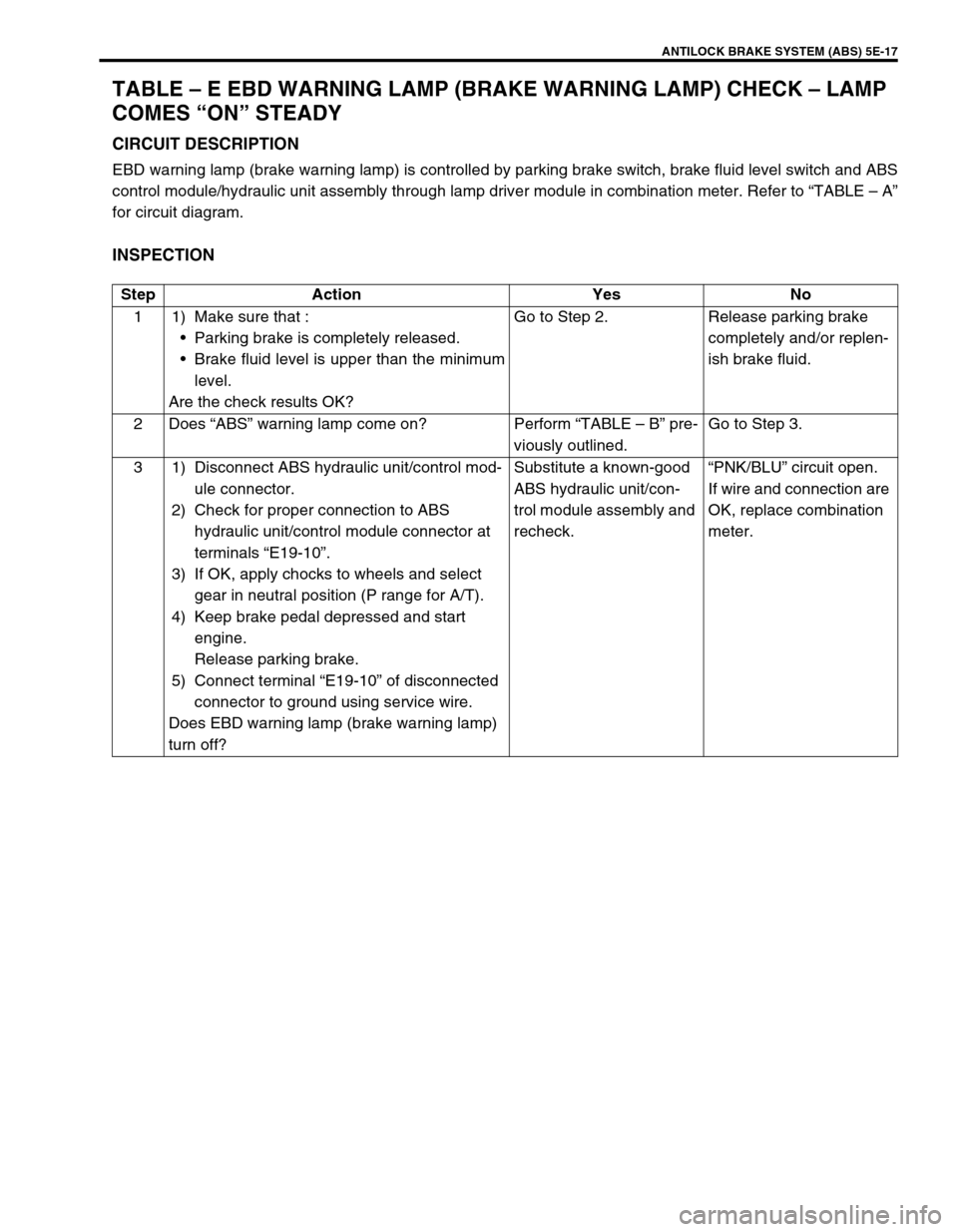
TABLE – E EBD WARNING LAMP (BRAKE WARNING LAMP) CHECK – LAMP
COMES “ON” STEADY
CIRCUIT DESCRIPTION
EBD warning lamp (brake warning lamp) is controlled by parking brake switch, brake fluid level switch and ABS
control module/hydraulic unit assembly through lamp driver module in combination meter. Refer to “TABLE – A”
for circuit diagram.
INSPECTION
Step Action Yes No
1 1) Make sure that :
Parking brake is completely released.
Brake fluid level is upper than the minimum
level.
Are the check results OK?Go to Step 2. Release parking brake
completely and/or replen-
ish brake fluid.
2Does “ABS” warning lamp come on? Perform “TABLE – B” pre-
viously outlined.Go to Step 3.
3 1) Disconnect ABS hydraulic unit/control mod-
ule connector.
2) Check for proper connection to ABS
hydraulic unit/control module connector at
terminals “E19-10”.
3) If OK, apply chocks to wheels and select
gear in neutral position (P range for A/T).
4) Keep brake pedal depressed and start
engine.
Release parking brake.
5) Connect terminal “E19-10” of disconnected
connector to ground using service wire.
Does EBD warning lamp (brake warning lamp)
turn off?Substitute a known-good
ABS hydraulic unit/con-
trol module assembly and
recheck.“PNK/BLU” circuit open.
If wire and connection are
OK, replace combination
meter.