Page 291 of 698

5-18 BRAKES
3) Remove caliper (1) from caliper carrier (2).
4) Remove brake pads (3).
INSPECTION
Check pad lining for wear. When wear exceeds limit, replace with
new one.
Brake pad thickness (lining thickness)
Standard : 10 mm (0.40 in.)
Limit : 1 mm (0.04 in.)
INSTALLATION
1) Set brake pad springs (1) and shim (2) and install brake
pads (3).
2) Install caliper and tighten caliper pin bolts (1) to specified
torque.
Tightening torque
Caliper pin bolts (a) : 26 N·m (2.6 kg-m, 19.0 lb-ft)
3) Tighten wheel temporarily and lower lift.NOTE:
Hang removed caliper (1) with a wire hook (4) or the like
so as to prevent brake hose from bending and twisting
excessively or being pulled.
Don’t operate brake pedal with brake pads removed.
CAUTION:
Never polish pad lining with sandpaper. If lining is pol-
ished with sandpaper, hard particles of sandpaper will be
deposited in lining and may damage disc. When pad lin-
ing requires correction, replace it with a new one.
NOTE:
When pads are removed, visually inspect caliper for
brake fluid leak. Correct leaky point, if any.
NOTE:
For right side brake, install pad with wear indicator (4) to
vehicle center side.
3
4
2
3
1
Page 292 of 698
BRAKES 5-19
4) Tighten wheel nuts to specified torque.
Tightening torque
Wheel nuts (a) : 85 N·m (8.5 kg-m, 61.5 lb-ft)
5) After completion of installation, check for brake effective-
ness.
CALIPER ASSEMBLY
REMOVAL
1) Hoist vehicle and remove wheel.
2) Remove E-ring (1).
3) Loosen flexible hose joint bolt (1) a little at caliper.
4) Remove caliper pin bolts (1).
5) Remove caliper from caliper carrier.
6) Disconnect flexible hose from caliper using care not to twist
it. As this will allow brake fluid to flow out of flexible hose,
have a container ready beforehand.
CAUTION:
Be careful not to twist flexible hose while loosening the
bolt.
Page 293 of 698
5-20 BRAKES
DISASSEMBLY
1) Remove piston with air blown into flexible hose bolt installa-
tion hole.
2) Remove cylinder boot (1).
3) Remove piston seal using a thin blade like a thickness
gauge, etc.
4) Remove bleeder plug and cap from caliper.
INSPECTION
Pin Boot and Cylinder Boot
Check boots for breakage, crack and damage.
If defective, replace.CAUTION:
Clean around caliper with brake fluid before disassem-
bly.
WARNING:
Do not apply too highly compressed air which will cause
piston to jump out of cylinder. Place a cloth (1) to prevent
piston from damage. It should be taken out gradually
with moderately compressed air. Do not place your fin-
gers in front of piston when using compressed air.
CAUTION:
Use care not to cause damage to cylinder boot.
1
CAUTION:
Be careful not to damage inside (bore side) of cylinder.
Page 294 of 698

BRAKES 5-21
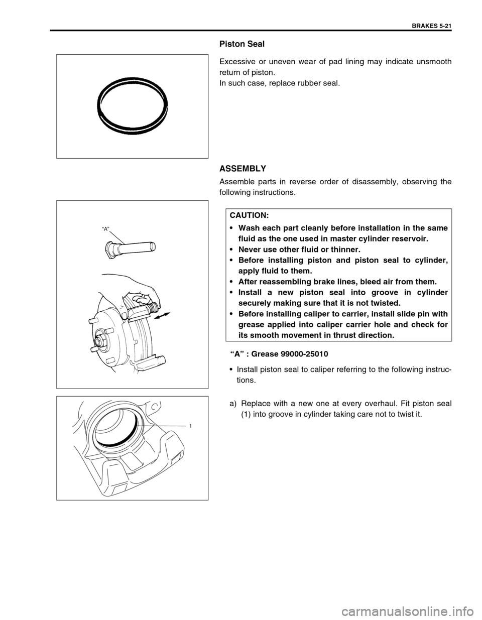
Piston Seal
Excessive or uneven wear of pad lining may indicate unsmooth
return of piston.
In such case, replace rubber seal.
ASSEMBLY
Assemble parts in reverse order of disassembly, observing the
following instructions.
“A” : Grease 99000-25010
Install piston seal to caliper referring to the following instruc-
tions.
a) Replace with a new one at every overhaul. Fit piston seal
(1) into groove in cylinder taking care not to twist it.
CAUTION:
Wash each part cleanly before installation in the same
fluid as the one used in master cylinder reservoir.
Never use other fluid or thinner.
Before installing piston and piston seal to cylinder,
apply fluid to them.
After reassembling brake lines, bleed air from them.
Install a new piston seal into groove in cylinder
securely making sure that it is not twisted.
Before installing caliper to carrier, install slide pin with
grease applied into caliper carrier hole and check for
its smooth movement in thrust direction.
1
Page 296 of 698

BRAKES 5-23
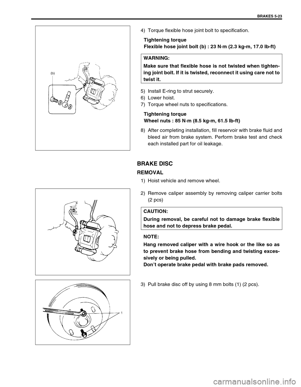
4) Torque flexible hose joint bolt to specification.
Tightening torque
Flexible hose joint bolt (b) : 23 N·m (2.3 kg-m, 17.0 Ib-ft)
5) Install E-ring to strut securely.
6) Lower hoist.
7) Torque wheel nuts to specifications.
Tightening torque
Wheel nuts : 85 N·m (8.5 kg-m, 61.5 Ib-ft)
8) After completing installation, fill reservoir with brake fluid and
bleed air from brake system. Perform brake test and check
each installed part for oil leakage.
BRAKE DISC
REMOVAL
1) Hoist vehicle and remove wheel.
2) Remove caliper assembly by removing caliper carrier bolts
(2 pcs)
3) Pull brake disc off by using 8 mm bolts (1) (2 pcs).WARNING:
Make sure that flexible hose is not twisted when tighten-
ing joint bolt. If it is twisted, reconnect it using care not to
twist it.
CAUTION:
During removal, be careful not to damage brake flexible
hose and not to depress brake pedal.
NOTE:
Hang removed caliper with a wire hook or the like so as
to prevent brake hose from bending and twisting exces-
sively or being pulled.
Don’t operate brake pedal with brake pads removed.
Page 298 of 698
BRAKES 5-25
REAR BRAKE
1. Brake back plate
: Apply water tight sealant (99000-31090) to joint seam of brake back plate and rear axle 9. Bleeder plug
2. Brake shoe10. Bleeder plug cap
3. Push nut 11. Parking lever spring
4. Shoe hold down spring12. Parking brake shoe lever
5. Shoe return upper spring 13. Brake Drum
6. Shoe hold down pin 14. Spindle nut (For 2WD vehicle only)
: Calk spindle nut after tightening
7. Brake strutTightening torque
8. Wheel cylinder
: Apply brake fluid to piston cup Do not reuse.
Page 300 of 698
BRAKES 5-27
b) For 4WD vehicle :
Pull brake drum off by using 8 mm bolts.
INSPECTION
Brake Drum
Inspect brake drum for wear.
If limit value of drum inner diameter is exceeded or uneven or
stepped wear is excessive, replace drum.
Drum inner diameter “a”
Standard : 180 mm (7.09 in.)
Limit : 182 mm (7.17 in.)
Brake Shoe
Measure thickness of brake shoe (1) (not including backing
metal). Also, check surface of lining for hardening, excessive
wear and oil.
Brake shoe thickness
Standard : 3.9 mm (0.15 in.)
Limit : 1.0 mm (0.04 in.)
NOTE:
When drum is removed, visually inspect wheel cylinder
for brake fluid leakage. Correct leaky point, if any.
CAUTION:
Never polish lining with sandpaper. If lining is polished
with sandpaper, hard particles of sandpaper will be
deposited in lining and may damage drum. When it is
required to correct lining, replace it with a new one.
Page 303 of 698
5-30 BRAKES
INSTALLATION
Install parts in reverse order of removal, noting the followings.
Install shoe hold down springs (2) by pushing them down in
place and turning hold down pins (1).
For procedure hereafter referring to “BRAKE DRUM”.
WHEEL CYLINDER
REMOVAL
1) Remove brake drum referring to “BRAKE DRUM”.
2) Remove break shoe referring to “BRAKE SHOE”.
3) Loosen brake pipe flare nut (1) but only within the extent that
fluid does not leak.
4) Remove wheel cylinder mounting bolts. Disconnect brake
pipe from wheel cylinder and put bleeder plug cap (1) onto
pipe to prevent fluid from spilling.
INSPECTION
Inspect wheel cylinder disassembled parts for wear, cracks, cor-
rosion or damage.
NOTE:
Clean wheel cylinder components with brake fluid.