Page 161 of 698

3B1-20 ELECTRICAL POWER STEERING (P/S) SYSTEM
DTC C1122 (DTC No.22) ENGINE SPEED SIGNAL CIRCUIT FAILURE
1. To main fuse 4.“IG METER” fuse (15A) in fuse box 7. Connector “G24”
2. Ignition switch 5. ECM
3.“P/S” fuse (30A) in fuse box 6. P/S control module
G24-2 G24-1
G24-8
G24-6 1
23
4
56
BLK/WHT BLK/RED
BRNBLK
G24-1
G24-6
G24-8G24-2
7
Step Action Yes No
1Was “SYSTEM CHECK FLOW TABLE” per-
formed?Go to STEP 2. Go to “SYSTEM CHECK
FLOW TABLE”.
2 1) Recheck DTC with engine running.
Is DTC C1122 (DTC No.22) indicated?Go to STEP 3. It is nothing abnormal for
DTC C1122 (DTC No.22).
P/S system is in normal
condition.
3 1) Check proper connection to P/S control mod-
ule and ECM at each “BRN” wire terminal (P/
S control module side: “G24-6” terminal, ECM
side : Refer to in SECTION 6E), then check
intermittent trouble. Refer to “INTERMITTENT
TROUBLE” in SECTION 0A.
2) If they are OK, check high resistance, open or
short to power circuit or ground in “BRN” wire
circuit.
Is check result in good condition?Substitute a known-
good P/S control mod-
ule and recheck.Repair.
Page 162 of 698

ELECTRICAL POWER STEERING (P/S) SYSTEM 3B1-21
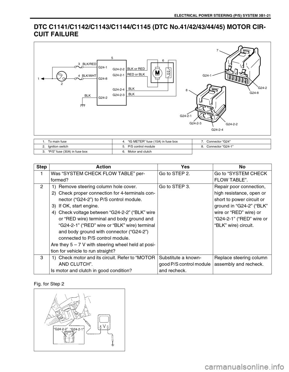
DTC C1141/C1142/C1143/C1144/C1145 (DTC No.41/42/43/44/45) MOTOR CIR-
CUIT FAILURE
Fig. for Step 2
1. To main fuse 4.“IG METER” fuse (15A) in fuse box 7. Connector “G24”
2. Ignition switch 5. P/S control module 8. Connector “G24-1”
3.“P/S” fuse (30A) in fuse box 6. Motor and clutch
MG24-1
G24-8G24-2
7
G24-2-2
G24-2-4 G24-2-3 G24-2-1
8
G24-2 G24-1
G24-8G24-2-2
G24-2-1
G24-2-4
G24-2-3 1
23
46 5
BLK/WHTBLK/RED
BLKBLK BLK RED or BLK BLK or RED
Step Action Yes No
1Was “SYSTEM CHECK FLOW TABLE” per-
formed?Go to STEP 2. Go to “SYSTEM CHECK
FLOW TABLE”.
2 1) Remove steering column hole cover.
2) Check proper connection for 4-terminals con-
nector (“G24-2”) to P/S control module.
3) If OK, start engine.
4) Check voltage between “G24-2-2” (“BLK” wire
or “RED wire) terminal and body ground and
“G24-2-1” (“RED” wire or “BLK” wire) terminal
and body ground with connector (“G24-2”)
connected to P/S control module.
Are they 5 – 7 V with steering wheel held at posi-
tion for vehicle to run straight?Go to STEP 3. Repair poor connection,
high resistance, open or
short to power circuit or
ground in “G24-2” (“BLK”
wire or “RED” wire) or
“G24-2-1” (“RED” wire or
“BLK” wire) circuit.
3 1) Check motor and its circuit. Refer to “MOTOR
AND CLUTCH”.
Is motor and clutch in good condition?Substitute a known-
good P/S control module
and recheck.Replace steering column
assembly and recheck.
Page 163 of 698

3B1-22 ELECTRICAL POWER STEERING (P/S) SYSTEM
DTC C1151 (DTC No.51) CLUTCH CIRCUIT FAILURE
1. To main fuse 4.“IG METER” fuse (15A) in fuse box 7. Connector “G24”
2. Ignition switch 5. P/S control module 8. Connector “G24-2”
3.“P/S” fuse (30A) in fuse box 6. Motor and clutch
M
G24-2 G24-1
G24-8G24-2-2
G24-2-1
G24-2-4
G24-2-3 1
23
46 5
BLK/WHTBLK/RED
BLKBLK BLK RED or BLKBLK or RED
G24-1
G24-8G24-2
7
G24-2-2
G24-2-4 G24-2-3 G24-2-1
8
Step Action Yes No
1Was “SYSTEM CHECK FLOW TABLE” per-
formed?Go to STEP 2. Go to “SYSTEM CHECK
FLOW TABLE”.
2 1) Remove steering column lower cover.
2) Check proper connection for 4-terminals
connector (“G24-2”) to P/S control module.
3) If OK, start engine.
4) Check voltage between “G24-2-4” (“BLK”
wire) terminal and body ground with con-
nector (“G24-2”) connected to P/S control
module.
Is it 0 V?Go to STEP 3. Repair poor connection,
high resistance, open or
short to power circuit or
ground in “G24-2-4”
(“BLK” wire) circuit.
3 1) Check voltage between “G24-2-3” (“BLK”
wire) terminal and body ground with con-
nector (“G24-2”) connected to P/S control
module.
Is it 10 – 14 V with steering wheel held at posi-
tion for vehicle to run straight?Go to STEP 4. Repair poor connection,
high resistance, open or
short to power circuit or
ground in “G24-2-3”
(“BLK” wire) circuit.
4 1) Check motor and its circuit. Refer to
“MOTOR AND CLUTCH”.
Is motor and clutch in good condition?Substitute a known-good
P/S control module and
recheck.Replace steering column
assembly and recheck.
Page 165 of 698

3B1-24 ELECTRICAL POWER STEERING (P/S) SYSTEM
DTC C1153(DTC No.53) P/S CONTROL MODULE POWER SUPPLY CIRCUIT
FAILURE
Fig. for Step 2
DTC C1152/C1154/C1155 (DTC No.52/54/55) P/S CONTROL MODULE FAILURE
Substitute a known-good P/S control module and recheck.
1. To main fuse 3.“P/S” fuse (30A) in fuse box 5. P/S control module
2. Ignition switch 4.“IG METER” fuse (15A) in fuse box 6. Connector “G24”
G24-2 G24-1
G24-8 13
45
BLK/WHT BLK/RED
BLK
G24-1
G24-8G24-2
6
Step Action Yes No
1Was “SYSTEM CHECK FLOW TABLE” per-
formed?Go to STEP 2. Go to “SYSTEM CHECK
FLOW TABLE”.
2 1) Remove steering column lower cover.
2) Check “P/S” fuse and proper connection to
P/S control module at “G24-1” (“BLK/WHT”
wire) terminal.
3) If OK, check voltage between “G24-1” termi-
nal and body ground with connector (“G24”)
connected to P/S control module.
Is it 10 – 14 V?Check intermittent trou-
ble. Refer to “INTERMIT-
TENT TROUBLE” in
SECTION 0A.
If OK, substitute a known-
good P/S control module
and recheck.Repair poor connection or
high resistance in “G24-1”
(“BLK/RED” wire) circuit.
Page 167 of 698
3B1-26 ELECTRICAL POWER STEERING (P/S) SYSTEM
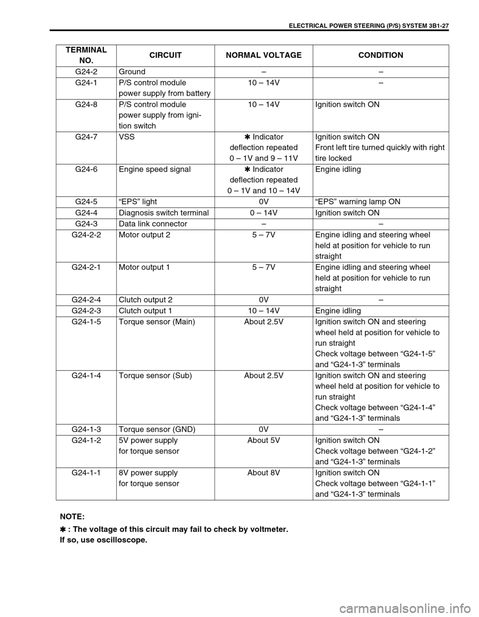
INSPECTION OF P/S CONTROL MODULE
AND ITS CIRCUITS
P/S control module (1) and its circuits can be checked at P/S con-
trol module wiring couplers (2) by measuring voltage and resis-
tance.
Voltage Check
1) Remove steering column lower cover with ignition switch
OFF position.
2) Check voltage at each terminal with connectors (2) con-
nected P/S control module. CAUTION:
P/S control module cannot be checked by itself. It is
strictly prohibited to connect voltmeter or ohmmeter to
P/S control module with connector disconnected from it.
NOTE:
As each terminal voltage is affected by the battery volt-
age, confirm that it is 11V or more when ignition switch is
ON.
Page 168 of 698

ELECTRICAL POWER STEERING (P/S) SYSTEM 3B1-27
TERMINAL
NO.CIRCUIT NORMAL VOLTAGE CONDITION
G24-2 Ground––
G24-1 P/S control module
power supply from battery10 – 14V–
G24-8 P/S control module
power supply from igni-
tion switch10 – 14V Ignition switch ON
G24-7 VSS✱ Indicator
deflection repeated
0 – 1V and 9 – 11VIgnition switch ON
Front left tire turned quickly with right
tire locked
G24-6 Engine speed signal✱ Indicator
deflection repeated
0 – 1V and 10 – 14VEngine idling
G24-5“EPS” light 0V“EPS” warning lamp ON
G24-4 Diagnosis switch terminal 0 – 14V Ignition switch ON
G24-3 Data link connector––
G24-2-2 Motor output 2 5 – 7V Engine idling and steering wheel
held at position for vehicle to run
straight
G24-2-1 Motor output 1 5 – 7V Engine idling and steering wheel
held at position for vehicle to run
straight
G24-2-4 Clutch output 2 0V–
G24-2-3 Clutch output 1 10 – 14V Engine idling
G24-1-5 Torque sensor (Main) About 2.5V Ignition switch ON and steering
wheel held at position for vehicle to
run straight
Check voltage between “G24-1-5”
and “G24-1-3” terminals
G24-1-4 Torque sensor (Sub) About 2.5V Ignition switch ON and steering
wheel held at position for vehicle to
run straight
Check voltage between “G24-1-4”
and “G24-1-3” terminals
G24-1-3 Torque sensor (GND) 0V–
G24-1-2 5V power supply
for torque sensorAbout 5V Ignition switch ON
Check voltage between “G24-1-2”
and “G24-1-3” terminals
G24-1-1 8V power supply
for torque sensorAbout 8V Ignition switch ON
Check voltage between “G24-1-1”
and “G24-1-3” terminals
NOTE:
✱
✱✱ ✱ : The voltage of this circuit may fail to check by voltmeter.
If so, use oscilloscope.
Page 170 of 698

ELECTRICAL POWER STEERING (P/S) SYSTEM 3B1-29
ON-VEHICLE SERVICE
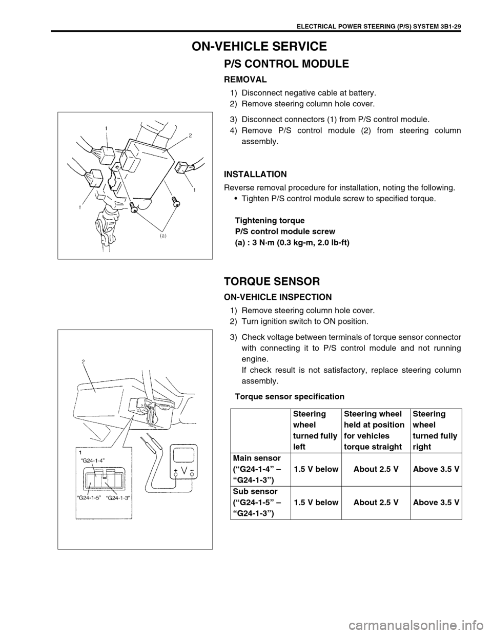
P/S CONTROL MODULE
REMOVAL
1) Disconnect negative cable at battery.
2) Remove steering column hole cover.
3) Disconnect connectors (1) from P/S control module.
4) Remove P/S control module (2) from steering column
assembly.
INSTALLATION
Reverse removal procedure for installation, noting the following.
Tighten P/S control module screw to specified torque.
Tightening torque
P/S control module screw
(a) : 3 N·m (0.3 kg-m, 2.0 lb-ft)
TORQUE SENSOR
ON-VEHICLE INSPECTION
1) Remove steering column hole cover.
2) Turn ignition switch to ON position.
3) Check voltage between terminals of torque sensor connector
with connecting it to P/S control module and not running
engine.
If check result is not satisfactory, replace steering column
assembly.
Torque sensor specification
Steering
wheel
turned fully
leftSteering wheel
held at position
for vehicles
torque straightSteering
wheel
turned fully
right
Main sensor
(“G24-1-4” –
“G24-1-3”)1.5 V below About 2.5 V Above 3.5 V
Sub sensor
(“G24-1-5” –
“G24-1-3”)1.5 V below About 2.5 V Above 3.5 V
Page 171 of 698

3B1-30 ELECTRICAL POWER STEERING (P/S) SYSTEM
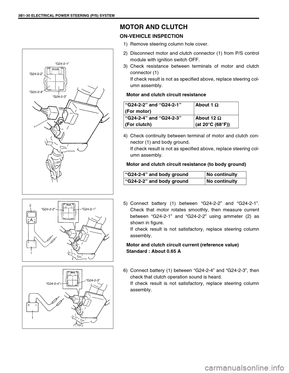
MOTOR AND CLUTCH
ON-VEHICLE INSPECTION
1) Remove steering column hole cover.
2) Disconnect motor and clutch connector (1) from P/S control
module with ignition switch OFF.
3) Check resistance between terminals of motor and clutch
connector (1)
If check result is not as specified above, replace steering col-
umn assembly.
Motor and clutch circuit resistance
4) Check continuity between terminal of motor and clutch con-
nector (1) and body ground.
If check result is not as specified above, replace steering col-
umn assembly.
Motor and clutch circuit resistance (to body ground)
5) Connect battery (1) between “G24-2-2” and “G24-2-1”.
Check that motor rotates smoothly, then measure current
between “G24-2-1” and “G24-2-2” using ammeter (2) as
shown in figure.
If check result is not satisfactory, replace steering column
assembly.
Motor and clutch circuit current (reference value)
Standard : About 0.65 A
6) Connect battery (1) between “G24-2-4” and “G24-2-3”, then
check that clutch operation sound is heard.
If check result is not satisfactory, replace steering column
assembly. “G24-2-2” and “G24-2-1”
(For motor)About 1
Ω
ΩΩ Ω
“G24-2-4” and “G24-2-3”
(For clutch)About 12
Ω
ΩΩ Ω
(at 20°C (68°F))
“G24-2-4” and body ground No continuity
“G24-2-2” and body ground No continuity