2000 SUZUKI SWIFT light
[x] Cancel search: lightPage 153 of 698
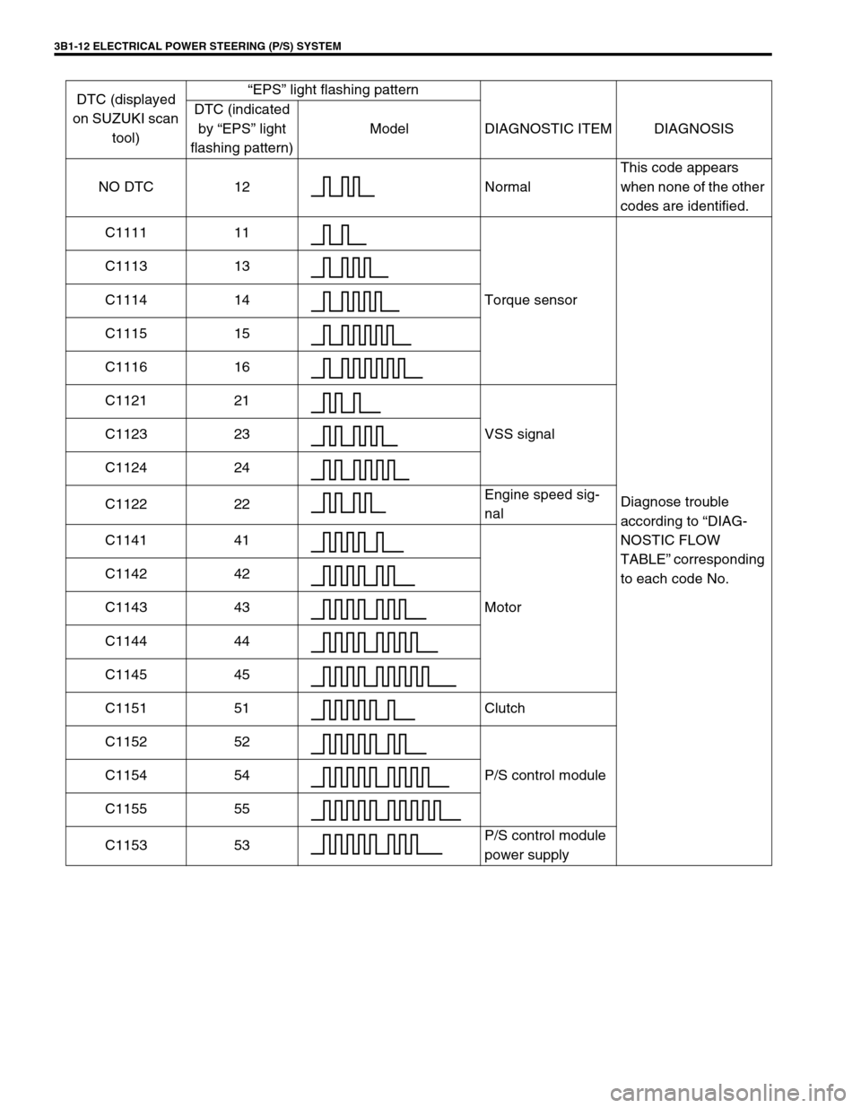
3B1-12 ELECTRICAL POWER STEERING (P/S) SYSTEM
DTC (displayed
on SUZUKI scan
tool)“EPS” light flashing pattern
DTC (indicated
by “EPS” light
flashing pattern)Model DIAGNOSTIC ITEM DIAGNOSIS
NO DTC 12 NormalThis code appears
when none of the other
codes are identified.
C1111 11
Torque sensor
Diagnose trouble
according to “DIAG-
NOSTIC FLOW
TABLE” corresponding
to each code No. C1113 13
C1114 14
C1115 15
C1116 16
C1121 21
VSS signal C1123 23
C1124 24
C1122 22Engine speed sig-
nal
C1141 41
Motor C1142 42
C1143 43
C1144 44
C1145 45
C1151 51 Clutch
C1152 52
P/S control module C1154 54
C1155 55
C1153 53P/S control module
power supply
Page 155 of 698
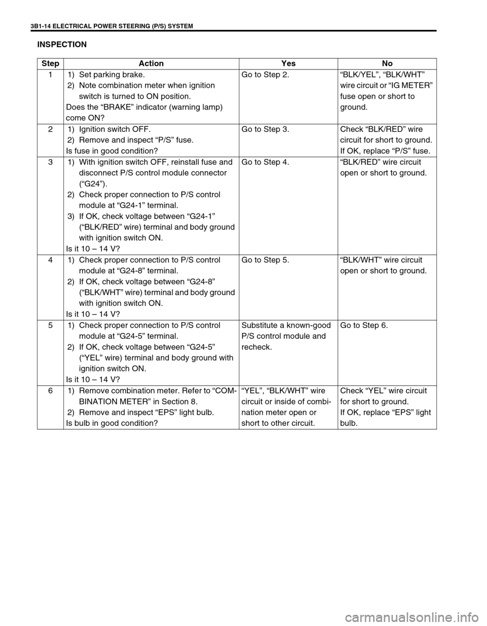
3B1-14 ELECTRICAL POWER STEERING (P/S) SYSTEM
INSPECTION
Step Action Yes No
1 1) Set parking brake.
2) Note combination meter when ignition
switch is turned to ON position.
Does the “BRAKE” indicator (warning lamp)
come ON?Go to Step 2.“BLK/YEL”, “BLK/WHT”
wire circuit or “IG METER”
fuse open or short to
ground.
2 1) Ignition switch OFF.
2) Remove and inspect “P/S” fuse.
Is fuse in good condition?Go to Step 3. Check “BLK/RED” wire
circuit for short to ground.
If OK, replace “P/S” fuse.
3 1) With ignition switch OFF, reinstall fuse and
disconnect P/S control module connector
(“G24”).
2) Check proper connection to P/S control
module at “G24-1” terminal.
3) If OK, check voltage between “G24-1”
(“BLK/RED” wire) terminal and body ground
with ignition switch ON.
Is it 10 – 14 V?Go to Step 4.“BLK/RED” wire circuit
open or short to ground.
4 1) Check proper connection to P/S control
module at “G24-8” terminal.
2) If OK, check voltage between “G24-8”
(“BLK/WHT” wire) terminal and body ground
with ignition switch ON.
Is it 10 – 14 V?Go to Step 5.“BLK/WHT” wire circuit
open or short to ground.
5 1) Check proper connection to P/S control
module at “G24-5” terminal.
2) If OK, check voltage between “G24-5”
(“YEL” wire) terminal and body ground with
ignition switch ON.
Is it 10 – 14 V?Substitute a known-good
P/S control module and
recheck.Go to Step 6.
6 1) Remove combination meter. Refer to “COM-
BINATION METER” in Section 8.
2) Remove and inspect “EPS” light bulb.
Is bulb in good condition?“YEL”, “BLK/WHT” wire
circuit or inside of combi-
nation meter open or
short to other circuit.Check “YEL” wire circuit
for short to ground.
If OK, replace “EPS” light
bulb.
Page 168 of 698
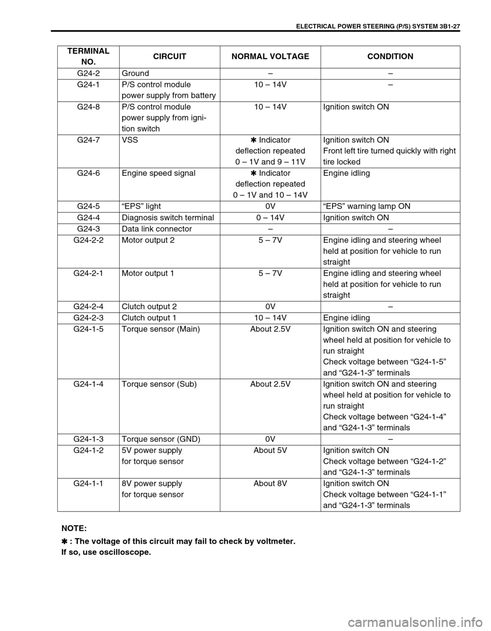
ELECTRICAL POWER STEERING (P/S) SYSTEM 3B1-27
TERMINAL
NO.CIRCUIT NORMAL VOLTAGE CONDITION
G24-2 Ground––
G24-1 P/S control module
power supply from battery10 – 14V–
G24-8 P/S control module
power supply from igni-
tion switch10 – 14V Ignition switch ON
G24-7 VSS✱ Indicator
deflection repeated
0 – 1V and 9 – 11VIgnition switch ON
Front left tire turned quickly with right
tire locked
G24-6 Engine speed signal✱ Indicator
deflection repeated
0 – 1V and 10 – 14VEngine idling
G24-5“EPS” light 0V“EPS” warning lamp ON
G24-4 Diagnosis switch terminal 0 – 14V Ignition switch ON
G24-3 Data link connector––
G24-2-2 Motor output 2 5 – 7V Engine idling and steering wheel
held at position for vehicle to run
straight
G24-2-1 Motor output 1 5 – 7V Engine idling and steering wheel
held at position for vehicle to run
straight
G24-2-4 Clutch output 2 0V–
G24-2-3 Clutch output 1 10 – 14V Engine idling
G24-1-5 Torque sensor (Main) About 2.5V Ignition switch ON and steering
wheel held at position for vehicle to
run straight
Check voltage between “G24-1-5”
and “G24-1-3” terminals
G24-1-4 Torque sensor (Sub) About 2.5V Ignition switch ON and steering
wheel held at position for vehicle to
run straight
Check voltage between “G24-1-4”
and “G24-1-3” terminals
G24-1-3 Torque sensor (GND) 0V–
G24-1-2 5V power supply
for torque sensorAbout 5V Ignition switch ON
Check voltage between “G24-1-2”
and “G24-1-3” terminals
G24-1-1 8V power supply
for torque sensorAbout 8V Ignition switch ON
Check voltage between “G24-1-1”
and “G24-1-3” terminals
NOTE:
✱
✱✱ ✱ : The voltage of this circuit may fail to check by voltmeter.
If so, use oscilloscope.
Page 180 of 698
STEERING WHEEL AND COLUMN 3C-7
INSTALLATION
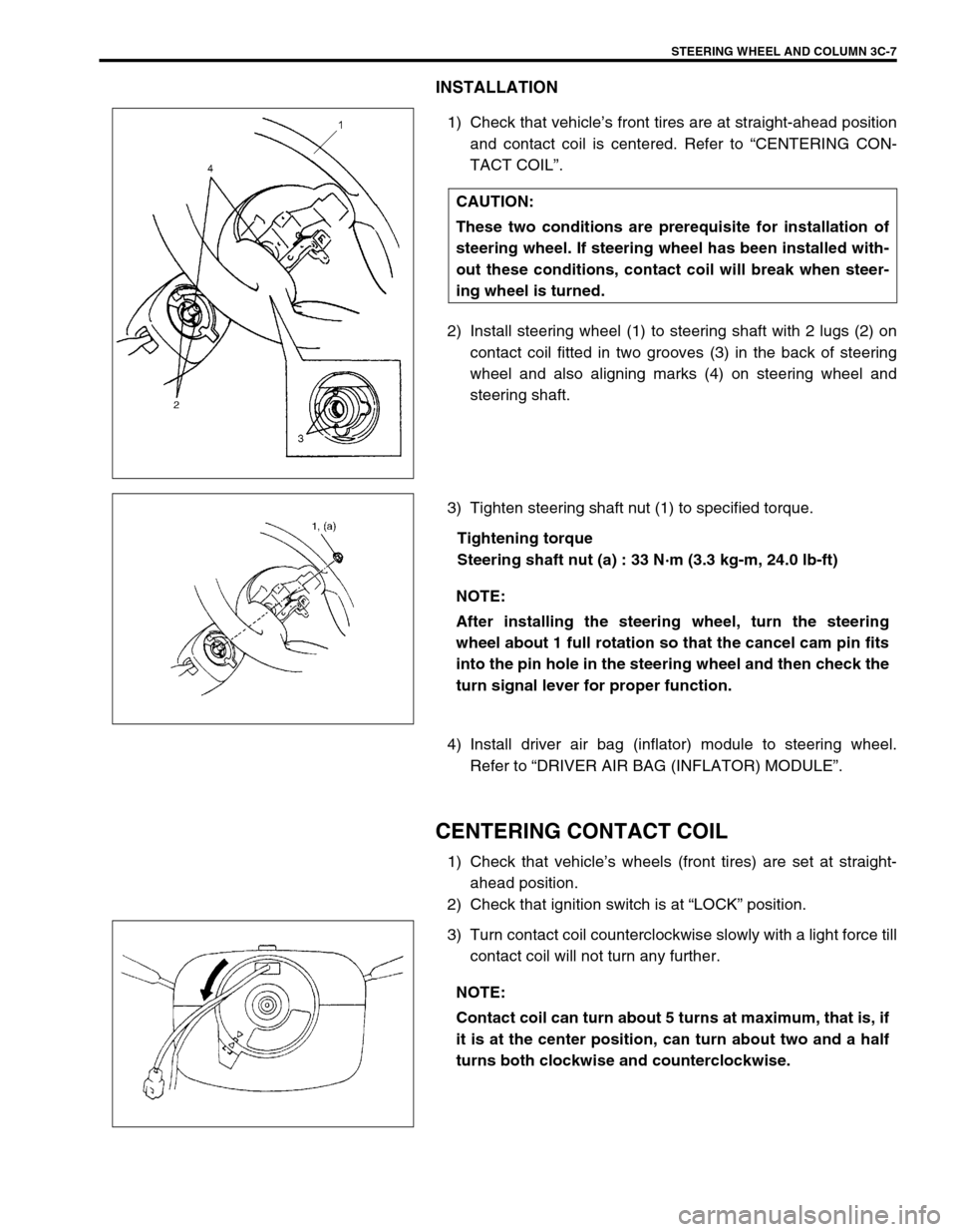
1) Check that vehicle’s front tires are at straight-ahead position
and contact coil is centered. Refer to “CENTERING CON-
TACT COIL”.
2) Install steering wheel (1) to steering shaft with 2 lugs (2) on
contact coil fitted in two grooves (3) in the back of steering
wheel and also aligning marks (4) on steering wheel and
steering shaft.
3) Tighten steering shaft nut (1) to specified torque.
Tightening torque
Steering shaft nut (a) : 33 N·m (3.3 kg-m, 24.0 lb-ft)
4) Install driver air bag (inflator) module to steering wheel.
Refer to “DRIVER AIR BAG (INFLATOR) MODULE”.
CENTERING CONTACT COIL
1) Check that vehicle’s wheels (front tires) are set at straight-
ahead position.
2) Check that ignition switch is at “LOCK” position.
3) Turn contact coil counterclockwise slowly with a light force till
contact coil will not turn any further. CAUTION:
These two conditions are prerequisite for installation of
steering wheel. If steering wheel has been installed with-
out these conditions, contact coil will break when steer-
ing wheel is turned.
NOTE:
After installing the steering wheel, turn the steering
wheel about 1 full rotation so that the cancel cam pin fits
into the pin hole in the steering wheel and then check the
turn signal lever for proper function.
NOTE:
Contact coil can turn about 5 turns at maximum, that is, if
it is at the center position, can turn about two and a half
turns both clockwise and counterclockwise.
Page 253 of 698
3F-8 WHEELS AND TIRES
TIRE
MOUNTING AND DISMOUNTING
Use a tire changing machine to mount or dismount tires. Follow equipment manufacturer’s instructions. Do not
use hand tools or tire irons alone to change tires as they may damage tire beads or wheel rim.
Rim bead seats should be cleaned with a wire brush or coarse steel wool to remove lubricants, old rubber and
light rust. Before mounting or dismounting a tire, bead area should be well lubricated with approved tire lubri-
cant.
After mounting, inflate to specified pressure shown on tire placard so that beads are completely seated.
Install valve core and inflate to proper pressure.
REPAIR
There are many different materials and techniques on the market to repair tires. As not all of these work on all
types of tires, tire manufacturers have published detailed instructions on how and when to repair tires. These
instructions can be obtained from each tire manufacturer.WARNING:
Do not stand over tire when inflating. Bead may break when bead snaps over rim’s safety hump and
cause serious personal injury.
Do not exceed specified pressure when inflating. If specified pressure will not seat beads, deflate, re-
lubricate and reinflate.
Over inflation may cause bead to break and cause serious personal injury.
Page 264 of 698
FRONT DRIVE SHAFT 4A-11
For DOJ Type Drive Shaft
Judging from abnormality noted before disassembly and what is
found though visual check of component parts after disassembly,
prepare replacing parts and proceed to reassembly.
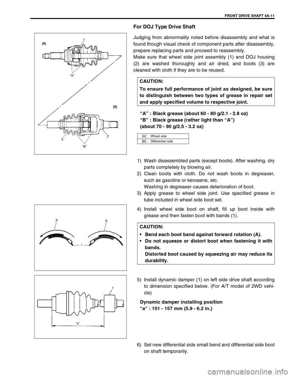
Make sure that wheel side joint assembly (1) and DOJ housing
(2) are washed thoroughly and air dried, and boots (3) are
cleaned with cloth if they are to be reused.
“A” : Black grease (about 60 - 80 g/2.1 - 2.8 oz)
“B” : Black grease (rather light than “A”)
(about 70 - 90 g/2.5 - 3.2 oz)
1) Wash disassembled parts (except boots). After washing. dry
parts completely by blowing air.
2) Clean boots with cloth. Do not wash boots in degreaser,
such as gasoline or kerosene, etc.
Washing in degreaser causes deterioration of boot.
3) Apply grease to wheel side joint. Use specified grease in
tube included in wheel side boot set.
4) Install wheel side boot on shaft, fill up boot inside with
grease and then fasten boot with bands (1).
5) Install dynamic damper (1) on left side drive shaft according
to dimension specified below. (For A/T model of 2WD vehi-
cle)
Dynamic damper installing position
“a” : 151 - 157 mm (5.9 - 6.2 in.)
6) Set new differential side small bend and differential side boot
on shaft temporarily. CAUTION:
To ensure full performance of joint as designed, be sure
to distinguish between two types of grease in repair set
and apply specified volume to respective joint.
[A] : Wheel side
[B] : Differential side
CAUTION:
Bend each boot band against forward rotation (A).
Do not squeeze or distort boot when fastening it with
bands.
Distorted boot caused by squeezing air may reduce its
durability.
Page 274 of 698
BRAKES 5-1
6F1
6F2
6G
6H
6K
7A
7A1
7B1
7C1
7D
7E
7F
8A
8B
8C
5
9
10
10A
10B
SECTION 5
BRAKES
CONTENTS
GENERAL DESCRIPTION ................................ 5-2
DIAGNOSIS ....................................................... 5-4
ROAD TESTING BRAKES ............................. 5-4
BRAKE FLUID LEAKS ................................... 5-4
SUBSTANDARD OR CONTAMINATED
BRAKE FLUID ................................................ 5-4
DIAGNOSIS TABLE ....................................... 5-5
BRAKE PEDAL FREE HEIGHT
ADJUSTMENT ............................................... 5-8
BRAKE PEDAL PLAY INSPECTION ............. 5-8
STOP LIGHT SWITCH ADJUSTMENT.......... 5-8
EXCESSIVE PEDAL TRAVEL
INSPECTION ................................................. 5-9
FRONT BRAKE PAD INSPECTION .............. 5-9
BRAKE DISC INSPECTION........................... 5-9
PARKING BRAKE INSPECTION AND
ADJUSTMENT ............................................. 5-10
BOOSTER OPERATION INSPECTION....... 5-11
FLUID PRESSURE TEST (IF EQUIPPED
WITH LSPV) ................................................ 5-12
MASTER CYLINDER AND BRAKE FLUID
LEVEL INSPECTION ................................... 5-14
BRAKE HOSE AND PIPE INSPECTION ..... 5-15
HOSE ....................................................... 5-15
PIPE ......................................................... 5-15
ON-VEHICLE SERVICE .................................. 5-15AIR BLEEDING OF BRAKE SYSTEM ......... 5-15
FRONT BRAKE ........................................... 5-17
BRAKE PAD............................................. 5-17
CALIPER ASSEMBLY ............................. 5-19
BRAKE DISC ........................................... 5-23
REAR BRAKE .............................................. 5-25
BRAKE DRUM ......................................... 5-26
BRAKE SHOE .......................................... 5-29
WHEEL CYLINDER ................................. 5-30
BRAKE BACK PLATE (FOR 2WD
VEHICLE)................................................. 5-31
BRAKE BACK PLATE (FOR 4WD
VEHICLE)................................................. 5-33
MASTER CYLINDER ................................... 5-33
MASTER CYLINDER RESERVOIR ......... 5-33
MASTER CYLINDER ASSEMBLY........... 5-34
BRAKE BOOSTER ...................................... 5-38
BRAKE HOSE/PIPE .................................... 5-41
FRONT BRAKE HOSE/PIPE ................... 5-41
REAR BRAKE HOSE/PIPE...................... 5-44
PARKING BRAKE CABLE ........................... 5-46
LSPV (LOAD SENSING PROPORTIONING
VALVE) ASSEMBLY (IF EQUIPPED).......... 5-48
REQUIRED SERVICE MATERIAL.................. 5-50
SPECIAL TOOL .............................................. 5-50
NOTE:
All front fasteners are important attaching parts in that they could affect the performance of vital parts
and systems, and/or could result in major repair expense. They must be replaced with one of same
part number or with an equivalent part if replacement becomes necessary. Do not use a replacement
part of lesser quality or substitute design. Torque values must be used as specified during reassem-
bly to assure proper retention of all parts. There is to be no welding as it may result in extensive dam-
age and weakening of the metal.
Page 277 of 698
5-4 BRAKES
DIAGNOSIS
ROAD TESTING BRAKES
Brakes should be tested on dry, clean, smooth and reasonably level roadway which is not crowned. Road test
brakes by making brake applications with both light and heavy pedal forces at various speeds to determine if the
vehicle stops evenly and effectively. Also drive vehicle to see if it leads to one side or the other without brake
application. If it does, check the tire pressure, front end alignment and front suspension attachments for loose-
ness. See diagnosis table for other causes.
BRAKE FLUID LEAKS
Check the master cylinder fluid levels. While a slight drop in reservoir level does result from normal lining wear,
an abnormally low level indicates a leak in the system. In such a case, check the entire brake system for leak-
age. If even a slight evidence of leakage is noted, the cause should be corrected or defective parts should be
replaced.
SUBSTANDARD OR CONTAMINATED BRAKE FLUID
Improper brake fluid, mineral oil or water in the fluid may cause the brake fluid to boil or the rubber components
in the hydraulic system to deteriorate.
If primary piston cups are swollen, then rubber parts have deteriorated. This deterioration may also be evi-
denced by swollen wheel cylinder piston cups on the drum brake wheels.
If deterioration of rubber is evident, disassemble all hydraulic parts and wash with alcohol. Dry these parts with
compressed air before assembly to keep alcohol out of the system. Replace all rubber parts in the system,
including hoses. Also, when working on the brake mechanisms, check for fluid on the linings.
If excessive fluid is found, replace the pads.
If master cylinder piston seals are satisfactory, check for leakage or excessive heat conditions. If leakage is not
found, drain fluid, flush with brake fluid, refill and bleed system.
The system must be flushed if there is any doubt as to the grade of fluid in the system or if fluid has been used
which contained parts that have been subjected to contaminated fluid.