Page 101 of 698
1B-36 AIR CONDITIONING (OPTIONAL)
A/C SWITCH
REMOVAL AND INSTALLATION
Refer to “HEATER CONTROL ASSEMBLY” in Section 1A.
INSPECTION
Press A/C switch button and check if there is continuity
between terminals “A” and “B”.
Connect battery voltage (+) to terminal “C” and (–) to termi-
nal “A”, and then press A/C Switch button and check if indi-
cator lamp lights.
RADIATOR/CONDENSER COOLING FAN
MOTOR RELAY No.1, No.2 and No.3
INSPECTION
Refer to “RADIATOR FAN RELAY” in Section 6B.
COMPRESSOR
REMOVAL
1) Run engine at idle speed with air conditioning ON for 10 min-
utes. After that stop the engine.
2) Disconnect negative (–) cable at battery.
3) Recover refrigerant from refrigeration system by referring to
“RECOVERY” in this section.
4) Remove front bumper by referring to “FRONT BUMPER” in
Section 8.
5) Remove engine food cover (1) from vehicle body.
NOTE:
The amount of removed compressor oil must be mea-
sured for replenishing compressor oil.
Page 134 of 698

MANUAL RACK AND PINION 3B-13
INSPECTION
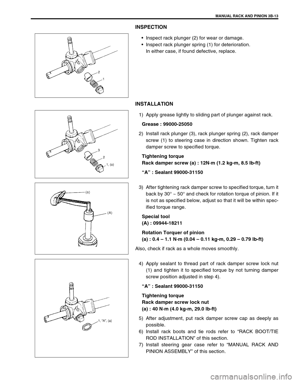
Inspect rack plunger (2) for wear or damage.
Inspect rack plunger spring (1) for deterioration.
In either case, if found defective, replace.
INSTALLATION
1) Apply grease lightly to sliding part of plunger against rack.
Grease : 99000-25050
2) Install rack plunger (3), rack plunger spring (2), rack damper
screw (1) to steering case in direction shown. Tighten rack
damper screw to specified torque.
Tightening torque
Rack damper screw (a) : 12N·m (1.2 kg-m, 8.5 lb-ft)
“A” : Sealant 99000-31150
3) After tightening rack damper screw to specified torque, turn it
back by 30° ~ 50° and check for rotation torque of pinion. If it
is not as specified below, adjust so that it will be within spec-
ified torque range.
Special tool
(A) : 09944-18211
Rotation Torquer of pinion
(a) : 0.4 – 1.1 N·m (0.04 – 0.11 kg-m, 0.29 – 0.79 lb-ft)
Also, check if rack as a whole moves smoothly.
4) Apply sealant to thread part of rack damper screw lock nut
(1) and tighten it to specified torque by not turning damper
screw position adjusted in step 4).
“A” : Sealant 99000-31150
Tightening torque
Rack damper screw lock nut
(a) : 40 N·m (4.0 kg-m, 29.0 lb-ft)
5) After adjustment, put rack damper screw cap as deeply as
possible.
6) Install rack boots and tie rods refer to “RACK BOOT/TIE
ROD INSTALLATION” of this section.
7) Install steering gear case refer to “MANUAL RACK AND
PINION ASSEMBLY” of this section.
Page 140 of 698

MANUAL RACK AND PINION 3B-19
INSTALLATION
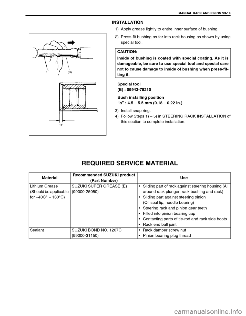
1) Apply grease lightly to entire inner surface of bushing.
2) Press-fit bushing as far into rack housing as shown by using
special tool.
Special tool
(B) : 09943-78210
Bush installing position
“a” : 4.5 – 5.5 mm (0.18 – 0.22 in.)
3) Install snap ring.
4) Follow Steps 1) – 5) in STEERING RACK INSTALLATION of
this section to complete installation.
REQUIRED SERVICE MATERIAL
CAUTION:
Inside of bushing is coated with special coating. As it is
damageable, be sure to use special tool and special care
not to cause damage to inside of bushing when press-fit-
ting it.
MaterialRecommended SUZUKI product
(Part Number)Use
Lithium Grease
(Should be applicable
for –40C° ~ 130°C)SUZUKI SUPER GREASE (E)
(99000-25050)Sliding part of rack against steering housing (All
around rack plunger, rack bushing and rack)
Sliding part against steering pinion
(Oil seal lip, needle bearing)
Steering rack and pinion gear teeth
Filled into pinion bearing cap
Contacting parts of tie-rod and rack side boots
Rack end ball joint
Sealant SUZUKI BOND NO. 1207C
(99000-31150)Rack damper screw nut
Pinion bearing plug thread
Page 145 of 698

3B1-4 ELECTRICAL POWER STEERING (P/S) SYSTEM
DIAGNOSIS
The P/S system in this vehicle is controlled by P/S control module. P/S control module has an on-board diagnos-
tic system which detects a malfunction in this system.
When diagnosing troubles, be sure to have full understanding of the outline of “ON-BOARD DIAGNOSTIC SYS-
TEM” and each item in “PRECAUTION IN DIAGNOSING TROUBLE” and execute diagnosis according to “SYS-
TEM CHECK FLOW TABLE”.
ON-BOARD DIAGNOSTIC SYSTEM
P/S control module performs on-board diagnosis (self-diagnosis)
on the system and operates “EPS” warning lamp (1) (malfunction
indicator lamp) as follows.
Malfunction indicator lamp (“EPS” warning lamp) lights when
the ignition switch is turned to ON position (but the engine at
stop) regardless of the condition of P/S control system. This
is only to check the malfunction indicator lamp (“EPS” warn-
ing lamp) bulb and its circuit.
If the areas monitored by P/S control module is free from any
trouble after the engine start (while engine is running), mal-
function indicator lamp (“EPS” warning lamp) turns OFF.
When P/S control module detects a trouble which has
occurred in the areas it monitors, malfunction indicator lamp
(“EPS” warning lamp) turns ON while the engine is running
to warn the driver of such occurrence of trouble and at the
same time it stores the exact trouble area in memory inside
of P/S control module.
PRECAUTIONS IN DIAGNOSING TROUBLES
Take a note of DTC indicated first.
Be sure to read “PRECAUTIONS FOR ELECTRONIC CIRCUIT SERVICE” in Section 0A before inspection
and observe what is written there.
When two or more troubles have occurred, their DTCs are indicated 3 times each starting with the smallest
code number and up.
DTC C1122 (DTC No.22) (engine speed signal failure) is indicated when ignition switch is ON position and
engine is not running but if indication changes to a normal one when engine is started, it means nothing
abnormal.
As DTC is stored in memory of P/S control module, be sure to clear memory after repair by performing the
procedure described in “DTC CLEARANCE”.
1
Page 146 of 698

ELECTRICAL POWER STEERING (P/S) SYSTEM 3B1-5
SYSTEM CHECK FLOW TABLE
Step Action Yes No
1 1) Record details of the problem (failure, complaint) and how it
occurred as described by the customer.
For this purpose, use of such a questionnaire from as shown
below will facilitate collecting information to the point required for
proper analysis and diagnosis.
2) Check if what the customer claimed in “CUSTOMER QUES-
TIONNAIRE” is actually found in the vehicle and if that symptom
is found, whether it is identified as a failure.
(This step should be shared with the customer if possible.)
3) Check malfunction indicator lamp (“EPS” warning lamp) opera-
tion referring to “MALFUNCTION INDICATOR LAMP (“EPS”
LIGHT) CHECK”.
4) Check DTC referring to “DTC CHECK” in this section and record
the DTC(s).
5) Clear DTC if any malfunction DTC exists referring to “DTC
CLEARANCE” in this section, then recheck DTC.
Is any malfunction DTC detected?Go to Step 2. Go to Step 3.
2 1) Inspect and repair referring to applicable “DTC TABLE” in this
section.
2) Clear DTC referring to “DTC CLEARANCE” in this section.
Does the trouble recur?Go to Step 5. Go to Step 4.
3 1) Test drive the vehicle and turn steering wheel fully to the right
and left during test driving. See WARNING. Check if any trouble
exists.
2) Inspect and repair basic parts referring to “DIAGNOSIS CHART”
in SECTION 3.
3) If the trouble cannot be repaired in Step 3-2), inspect and repair
referring to “TROUBLE DIAGNOSIS (FOR TROUBLE NOT INDI-
CATED BY ON-BOARD DIAGNOSTIC SYSTEM)” in this sec-
tion.
Does the trouble recur?Go to Step 5. Go to Step 4.
4 1) Confirm that the problem symptom has gone and P/S system is
free from any abnormal conditions. If what has been repaired is
related to the malfunction DTC, clear the DTC once and perform
test driving as in Step 3-1) and confirm that no DTC is indicated.
Is any malfunction DTC detected?Go to Step 5. END
5 1) Check DTC referring to “DTC CHECK” in this section.
Is any malfunction DTC detected?Go to Step 2. Go to Step 3.
WARNING:
Carry out test in very little traffic area to prevent an accident.
Page 147 of 698

3B1-6 ELECTRICAL POWER STEERING (P/S) SYSTEM
For identify current DTC, clear history DTC referring to “DTC CLEARANCE” in this section. NOTE:
As execution of “DTC CLEARANCE” will clear all malfunction DTCs, be sure to record all DTCs
before servicing.
When 2 or more codes are indicated, the lowest numbered code will appear first.
If a code not listed on “DTC TABLE” is displayed, then the P/S control module is faulty.
DTC C1122 or DTC No.22 (flashing pattern : 22) is indicated when ignition switch is ON and engine
is not running but if DTC No.12 (flashing pattern : 12) is indicated when engine is started, it means
nothing abnormal.
Current DTC and history DTC can be identified by lighting and flashing of “EPS” warning lamp.
“EPS” warning lamp operates as follow depending on the trouble condition.
Current DTC is set.
(Abnormality exists at
present.)History DTC is set only.
(Faulty condition occurred
once in the past but normal
condition is restored at
present.)Current DTC and history
DTC exist.
“EPS” warning lamp after
engine startedRemains ON. Turn OFF. Remains ON.
“EPS” warning lamp when
shorting diagnosis switch ter-
minal and ground terminalDisplays current DTC. Displays history DTC.Displays current DTC and
history DTC.
Page 148 of 698
ELECTRICAL POWER STEERING (P/S) SYSTEM 3B1-7
CUSTOMER QUESTIONNAIRE (EXAMPLE)
MALFUNCTION INDICATOR LAMP
(“EPS” WARNING LAMP) CHECK
1) Turn ignition switch to ON position (but without running
engine), check that malfunction indicator lamp (“EPS” warn-
ing lamp) lights up. If lamp does not light up, go to “TABLE
A”. If lamp flashes, go to “TABLE B”.
2) Start engine and check that malfunction indictor lamp
(“CHECK ENGIE” light) turns OFF.
If lamp comes OFF, P/S system is in good condition.
Page 152 of 698

ELECTRICAL POWER STEERING (P/S) SYSTEM 3B1-11
Fig. for Step 4
DTC TABLE
3 1) Check if communication is possible by trying
communication with other controller
(ECM, ABS hydraulic unit/control module
assembly (if equipped) or SDM).
Is it possible to communicate with other control-
ler?Go to Step 4. Repair open in common
section of serial data cir-
cuit (“BLU” wire circuit)
used by all controllers or
short to ground or power
circuit which has occurred
somewhere in serial data
circuit (“BLU” wire circuit).
4 1) With ignition switch is OFF position, discon-
nect 8-pin (“G24”) connector from P/S con-
trol module.
2) Check proper connection at “G24-3” (“BLU”
wire) terminal for serial data circuit.
3) If OK, then check resistance between “G24-
3” (“BLU” wire) terminal and “BLU” wire ter-
minal for serial data circuit in DLC.
Is resistance 1 Ω or less?Substitute a known-good
P/S control module and
recheck.Repair high resistance or
open in “BLU” wire circuit
for P/S system. Step Action Yes No
1. DLC
2.“BLU” wire terminal
CAUTION:
Be sure to perform “SYSTEM CHECK FLOW TABLE” before starting diagnosis according to flow table
of each DTC.
21
3.0
0.3
0.30.3 0.31.0 3.03.0 21 21
Example : When VSS circuit fail (DTC 1121, DTC No.21) is set
“EPS” lightTurn ON
Turn OFF
TIME
(sec.)