2000 SUZUKI SWIFT light
[x] Cancel search: lightPage 1 of 698

IMPORTANT
WARNING/CAUTION/NOTE
Please read this manual and follow its instructions carefully. To emphasize special information, the words
WARNING, CAUTION
and NOTE
have special meanings. Pay special attention to the messages highlighted by
these signal words.
WARNING:
Indicates a potential hazard that could result in death or injury.
CAUTION:
Indicates a potential hazard that could result in vehicle damage.
NOTE:
Indicates special information to make maintenance easier or instructions clearer.
WARNING:
This service manual is intended for authorized Suzuki dealers and qualified service mechanics only.
Inexperienced mechanics or mechanics without the proper tools and equipment may not be able to
properly perform the services described in this manual.
Improper repair may result in injury to the mechanic and may render the vehicle unsafe for the driver
and passengers.
WARNING:
For vehicles equipped with a Supplemental Restraint (Air Bag) System:
• Service on and around the air bag system components or wiring must be performed only by an
authorized SUZUKI dealer. Refer to “Air Bag System Components and Wiring Location View” under
“General Description” in air bag system section in order to confirm whether you are performing ser-
vice on or near the air bag system components or wiring. Please observe all WARNINGS and “Ser-
vice Precautions” under “On-Vehicle Service” in air bag system section before performing service
on or around the air bag system components or wiring. Failure to follow WARNINGS could result in
unintentional activation of the system or could render the system inoperative. Either of these two
conditions may result in severe injury.
If the air bag system and another vehicle system both need repair, Suzuki recommends that the air
bag system be repaired first, to help avoid unintended air bag system activation.
Do not modify the steering wheel, instrument panel or any other air bag system component (on or
around air bag system components or wiring). Modifications can adversely affect air bag system
performance and lead to injury.
If the vehicle will be exposed to temperatures over 93°C (200°F) (for example, during a paint baking
process), remove the air bag system components (air bag (inflator) modules, SDM and/or seat belt
with pretensioner) beforehand to avoid component damage or unintended activation.
Page 8 of 698

GENERAL INFORMATION 0A-5
Even when the accident was light enough not to cause air bags to activate, be sure to inspect sys-
tem parts and other related parts according to instructions under “REPAIR AND INSPECTION
REQUIRED AFTER AN ACCIDENT” in SECTION 10B.
When servicing parts other than air bag system, if shocks may be applied to air bag system compo-
nent parts, remove those parts beforehand.
When handling the air bag (inflator) modules (driver and passenger), seat belt pretensioners (driver
and passenger) or SDM, be careful not to drop it or apply an impact to it. If an excessive impact was
applied, never attempt disassembly or repair but replace it with a new one.
When grease, cleaning agent, oil, water, etc. has got onto air bag (inflator) modules (driver and pas-
senger) or seat belt pretensioners (drive and passenger), wipe off immediately with a dry cloth. WARNING:
SDM
For handling and storage of a SDM, select a place where the ambient temperature below 65°C
(150°F), without high humidity and away from electric noise.
During service procedures, be very careful when handling a Sensing and Diagnostic Module (SDM).
Never strike or jar the SDM.
Never power up the air bag system when the SDM is not rigidly attached to the vehicle. All SDM and
mounting bracket fasteners must be carefully torqued and the arrow must be pointing toward the
front of the vehicle to ensure proper operation of the air bag system.
The SDM could be activated when powered while not rigidly attached to the vehicle which could
cause deployment and result in personal injury.
WARNING:
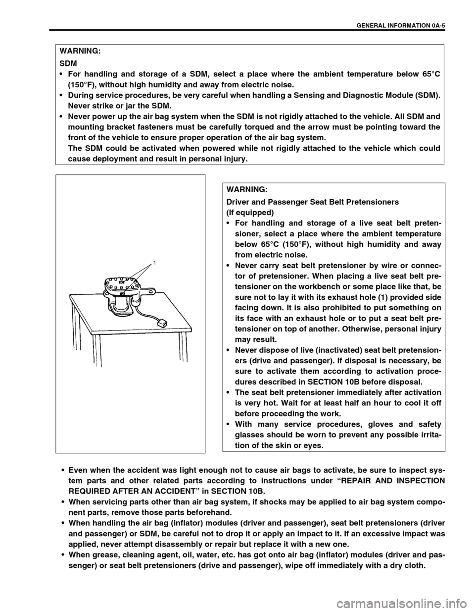
Driver and Passenger Seat Belt Pretensioners
(If equipped)
For handling and storage of a live seat belt preten-
sioner, select a place where the ambient temperature
below 65°C (150°F), without high humidity and away
from electric noise.
Never carry seat belt pretensioner by wire or connec-
tor of pretensioner. When placing a live seat belt pre-
tensioner on the workbench or some place like that, be
sure not to lay it with its exhaust hole (1) provided side
facing down. It is also prohibited to put something on
its face with an exhaust hole or to put a seat belt pre-
tensioner on top of another. Otherwise, personal injury
may result.
Never dispose of live (inactivated) seat belt pretension-
ers (drive and passenger). If disposal is necessary, be
sure to activate them according to activation proce-
dures described in SECTION 10B before disposal.
The seat belt pretensioner immediately after activation
is very hot. Wait for at least half an hour to cool it off
before proceeding the work.
With many service procedures, gloves and safety
glasses should be worn to prevent any possible irrita-
tion of the skin or eyes.
Page 20 of 698

GENERAL INFORMATION 0A-17
Improperly formed or damaged terminals.
Check each connector terminal in problem circuits carefully
to ensure good contact tension by using the corresponding
mating terminal.
If contact tension is not enough, reform it to increase contact
tension or replace.
Poor terminal-to-wire connection.
Check each wire harness in problem circuits for poor con-
nection by shaking it by hand lightly. If any abnormal condi-
tion is found, repair or replace.
Wire insulation which is rubbed through, causing an intermit-
tent short as the bare area touches other wiring or parts of
the vehicle.
Wiring broken inside the insulation. This condition could
cause continuity check to show a good circuit, but if only 1 or
2 strands of a multi-strand-type wire are intact, resistance
could be far too high.
If any abnormality is found, repair or replace.
1. Check contact tension by inserting and removing just once.
2. Check each terminal for bend and proper alignment.
Page 25 of 698

0A-22 GENERAL INFORMATION
ABBREVIATIONS AND SYMBOLS MAY BE USED IN THIS MANUAL
ABBREVIATIONS
AABS Anti-lock Brake System
EEFE Heater Early Fuel Evaporation Heater
(Positive Temperature Coefficient,
PTC Heater) ATDC After Top Dead Center
API American Petroleum Institute
ATF Automatic Transmission Fluid EPS Electronic Power Steering
ALR Automatic Locking Retractor EVAP Evaporative Emission
AC Alternating Current EVAP Canister Evaporative Emission Canister
(Charcoal Canister)
A/T Automatic TransmissionF
4WD 4 Wheel Drive
A/C Air Conditioning
GGEN Generator
ABDC After Bottom Dead Center GND Ground
A/F Air Fuel Mixture Ratio
HHC Hydrocarbons
A-ELR Automatic-Emergency Locking
RetractorHO2S Heated Oxygen Sensor
IIAC Valve Idle Air Control Valve (Idle Speed
Control Solenoid Valve ISC Sole-
noid Valve)
BB+ Battery Positive Voltage
BTDC Before Top Dead Center
BBDC Before Bottom Dead Center IAT Sensor Intake Air Temperature Sensor
(Air temperature Sensor, ATS)
CCKT Circuit
CKP sensor Crankshaft Position Sensor ICM Immobilizer Control Module
CMP sensor Camshaft Position Sensor IG Ignition
CO Carbon Monoxide ISC Actuator Idle Speed Control Actuator
CPP switch Clutch Pedal Position Switch
(Clutch Switch, Clutch Start
Switch)LLH Left Hand
LSPV Load Sensing Proportioning Valve
CPU Central Processing Unit
MMAF Sensor Mass Air Flow Sensor (Air Flow
Sensor, AFS, Air Flow Meter,
AFM) CRS Child Restraint System
DDC Direct Current
DLC Data Link Connector (Assembly
Line Diag. Link, ALDL, Serial Data
Link, SDL)MAP Sensor Manifold Absolute Pressure Sen-
sor (Pressure Sensor, PS)
Max Maximum
DOHC Double Over Head Camshaft MFI Multiport Fuel Injection
(Multipoint Fuel Injection)
DOJ Double Offset Joint
DRL Daytime Running Light MIN Minimum
DTC Diagnostic Trouble Code (Diag-
nostic Code)MIL Malfunction Indicator Lamp
(“SERVICE ENGINE SOON”
Light)
EEBCM Electronic Brake Control Module,
ABS Control Module M/T Manual Transmission
EBD Electronic Brake Force Distribu-
tionNNOx Nitrogen Oxides
ECM Engine Control Module
OOBD On-Board Diagnostic System
(Self-Diagnosis Function)
ECT sensor Engine Coolant Temperature Sen-
sor (Water Temp. Sensor, WTS)
O/D Overdrive
EGR Exhaust Gas Recirculation OHC Over Head Camshaft
EGRT sensor EGR Temperature Sensor (Recir-
culated Exhaust Gas Temp. Sen-
sor, REGTS)O2S Oxygen Sensor
PPNP Park/Neutral Position
P/S Power Steering
Page 27 of 698

0A-24 GENERAL INFORMATION
SYMBOLS
WIRE COLOR SYMBOLS
There are two kinds of colored wire used in this vehicle. One is
single-colored wire and the other is dual-colored (striped) wire.
The single-colored wire uses only one color symbol (i.e. “GRN”).
The dual-colored wire uses two color symbols (i.e. “GRN/YEL”).
The first symbol represents the base color of the wire (“GRN” in
the figure) and the second symbol represents the color of the
stripe (“YEL” in the figure). SYMBOL DEFINITION SYMBOL DEFINITION
Tightening torque Apply SUZUKI BOND NO. 1216
99000-31160
Apply oil (engine, transmission, trans-
fer, differential)Apply SILICONE SEALANT
99000-31120
Apply fluid (brake, power steering or
automatic transmission fluid)Apply SEALING COMPOUND 366E
99000-31090
Apply SUZUKI SUPER GREASE A
99000-25010
Apply SUZUKI SUPER GREASE C
99000-25030Apply THREAD LOCK 1322
99000-32110
Apply SUZUKI SUPER GREASE E
99000-25050Apply THREAD LOCK 1333B
99000-32020
Apply SUZUKI SUPER GREASE H
99000-25120Apply THREAD LOCK 1342
99000-32050
Apply SUZUKI SUPER GREASE I
99000-25210
Apply SUZUKI BOND NO. 1215
99000-31110Do not reuse
Apply SUZUKI BOND NO. 1207C
99000-31150Note on reassembly
Symbol Wire Color Symbol Wire Color
B BLK Black O, Or ORN Orange
Bl BLU Blue R RED Red
Br BRN Brown W WHT White
GGRN Green Y YEL Yellow
Gr GRY Gray P PNK Pink
Lbl LT BLU Light blue V PPL Violet
Lg LT GRN Light green
Page 28 of 698

GENERAL INFORMATION 0A-25
FASTENER INFORMATION
METRIC FASTENERS
Most of the fasteners used for this vehicle are metric. When replacing any fasteners, it is most important that
replacement fasteners be the correct diameter, thread pitch and strength.
FASTENER STRENGTH IDENTIFICATION
Most commonly used metric fastener strength property classes are 4T, 6.8, 7T, 8.8 and radial line with the class
identification embossed on the head of each bolt. Some metric nuts will be marked with punch, 6 or 8 mark
strength identification on the nut face. Figure shows the different strength markings.
When replacing metric fasteners, be careful to use bolts and nuts of the same strength or greater than the origi-
nal fasteners (the same number marking or higher). It is likewise important to select replacement fasteners of
the correct diameter and thread pitch. Correct replacement bolts and nuts are available through the parts divi-
sion.
Metric bolts : Identification class numbers or marks correspond to bolt strength (increasing numbers represent
increasing strength).
STANDARD TIGHTENING TORQUE
Each fastener should be tightened to the torque specified in each section of this manual. If no description or
specification is provided, refer to the following tightening torque chart for the applicable torque for each fastener.
When a fastener of greater strength than the original one is used, however, use the torque specified for the orig-
inal fastener.
1. Nut strength identification
NOTE:
For the flanged bolt, flanged nut and self-lock nut of 4T and 7T strength, add 10% to the tightening
torque given in the chart below.
The chart below is applicable only where the fastened parts are made of steel light alloy.
Page 42 of 698

MAINTENANCE AND LUBRICATION 0B-13
BRAKE DRUMS AND SHOES (REAR)
INSPECTION
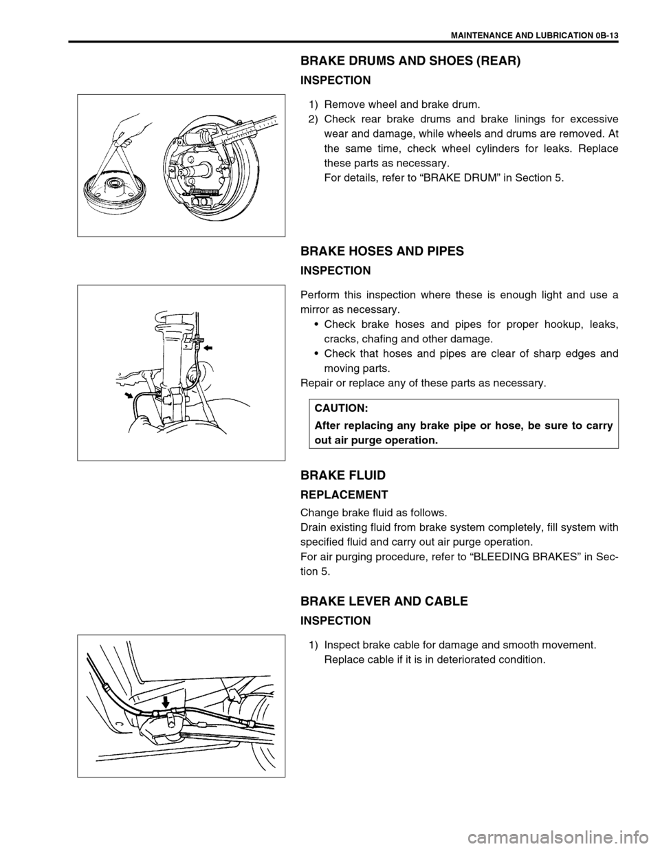
1) Remove wheel and brake drum.
2) Check rear brake drums and brake linings for excessive
wear and damage, while wheels and drums are removed. At
the same time, check wheel cylinders for leaks. Replace
these parts as necessary.
For details, refer to “BRAKE DRUM” in Section 5.
BRAKE HOSES AND PIPES
INSPECTION
Perform this inspection where these is enough light and use a
mirror as necessary.
Check brake hoses and pipes for proper hookup, leaks,
cracks, chafing and other damage.
Check that hoses and pipes are clear of sharp edges and
moving parts.
Repair or replace any of these parts as necessary.
BRAKE FLUID
REPLACEMENT
Change brake fluid as follows.
Drain existing fluid from brake system completely, fill system with
specified fluid and carry out air purge operation.
For air purging procedure, refer to “BLEEDING BRAKES” in Sec-
tion 5.
BRAKE LEVER AND CABLE
INSPECTION
1) Inspect brake cable for damage and smooth movement.
Replace cable if it is in deteriorated condition.
CAUTION:
After replacing any brake pipe or hose, be sure to carry
out air purge operation.
Page 45 of 698

0B-16 MAINTENANCE AND LUBRICATION
3) Check steering linkage for looseness and damage. Repair or
replace defective parts, if any.
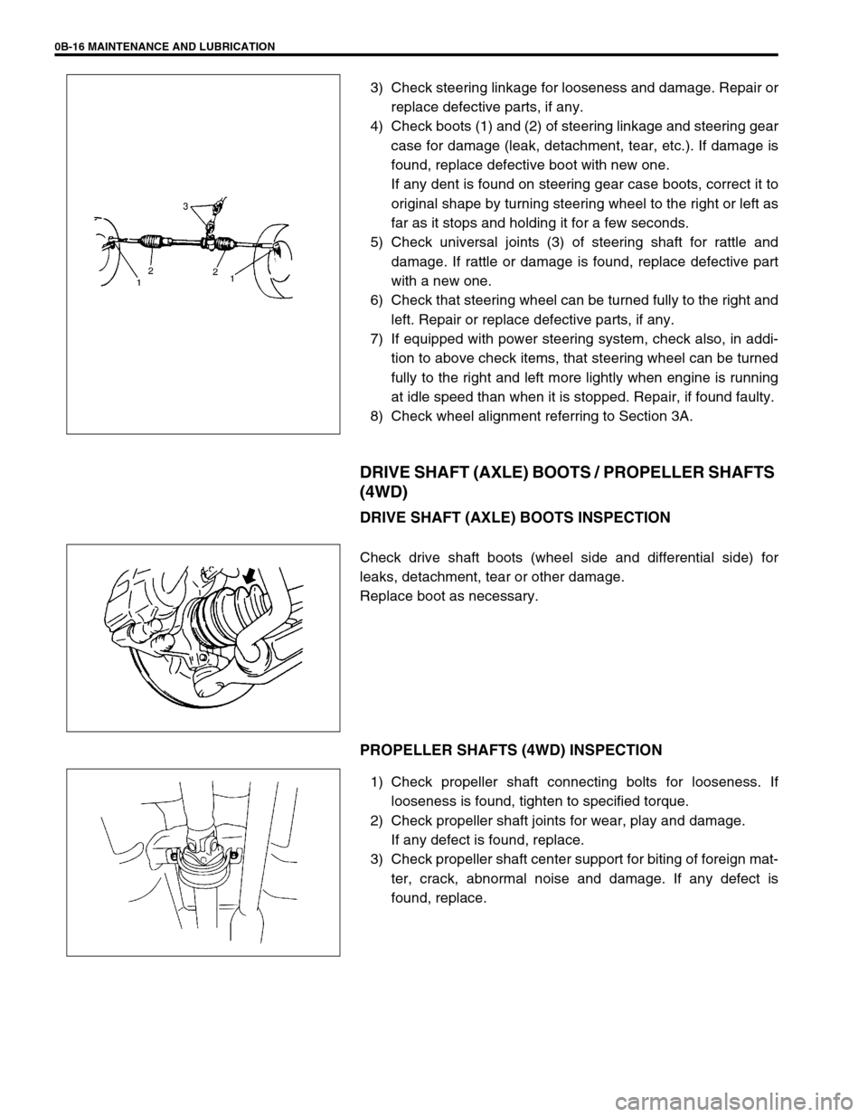
4) Check boots (1) and (2) of steering linkage and steering gear
case for damage (leak, detachment, tear, etc.). If damage is
found, replace defective boot with new one.
If any dent is found on steering gear case boots, correct it to
original shape by turning steering wheel to the right or left as
far as it stops and holding it for a few seconds.
5) Check universal joints (3) of steering shaft for rattle and
damage. If rattle or damage is found, replace defective part
with a new one.
6) Check that steering wheel can be turned fully to the right and
left. Repair or replace defective parts, if any.
7) If equipped with power steering system, check also, in addi-
tion to above check items, that steering wheel can be turned
fully to the right and left more lightly when engine is running
at idle speed than when it is stopped. Repair, if found faulty.
8) Check wheel alignment referring to Section 3A.
DRIVE SHAFT (AXLE) BOOTS / PROPELLER SHAFTS
(4WD)
DRIVE SHAFT (AXLE) BOOTS INSPECTION
Check drive shaft boots (wheel side and differential side) for
leaks, detachment, tear or other damage.
Replace boot as necessary.
PROPELLER SHAFTS (4WD) INSPECTION
1) Check propeller shaft connecting bolts for looseness. If
looseness is found, tighten to specified torque.
2) Check propeller shaft joints for wear, play and damage.
If any defect is found, replace.
3) Check propeller shaft center support for biting of foreign mat-
ter, crack, abnormal noise and damage. If any defect is
found, replace.