2000 SUZUKI SWIFT clutch
[x] Cancel search: clutchPage 162 of 698
ELECTRICAL POWER STEERING (P/S) SYSTEM 3B1-21
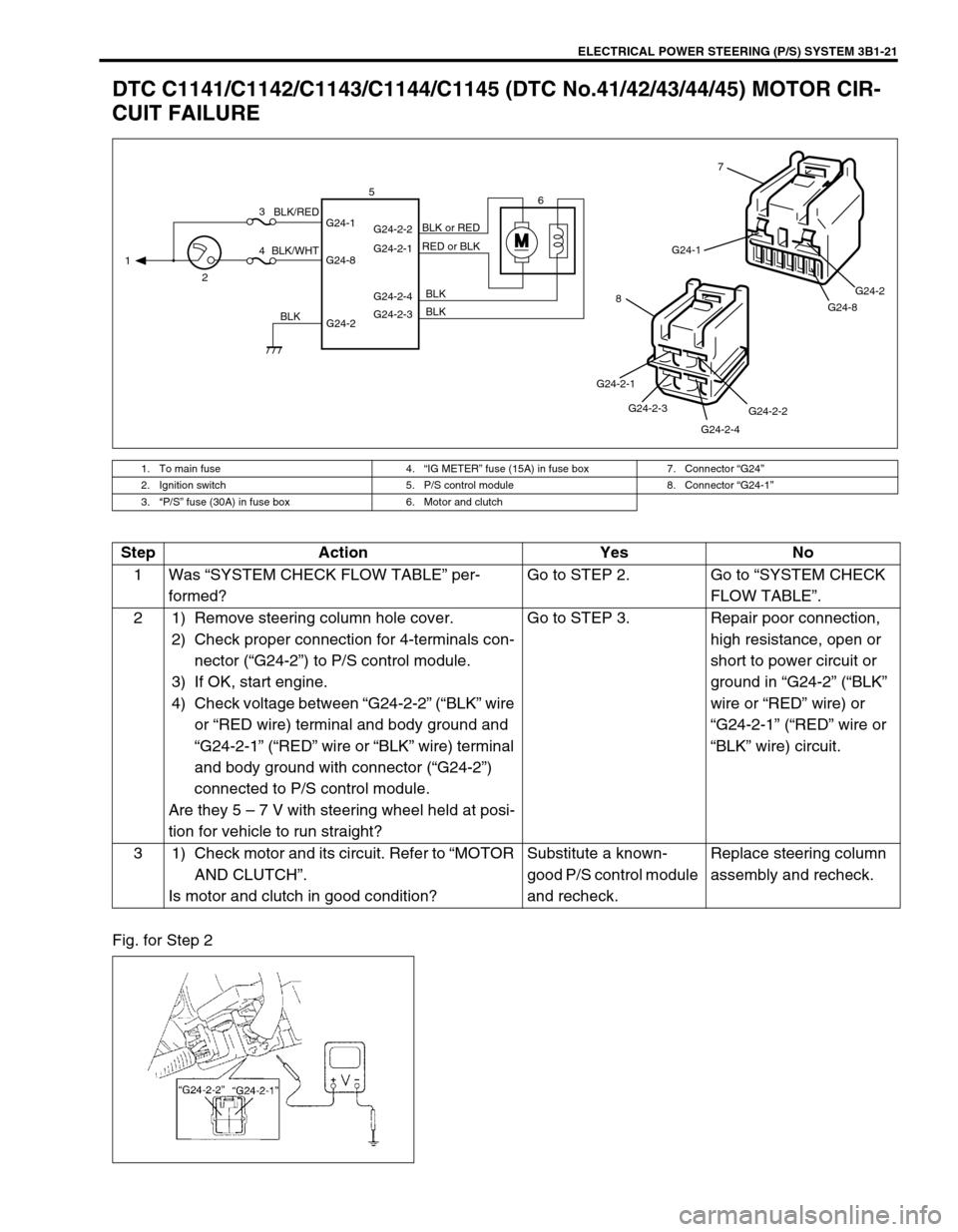
DTC C1141/C1142/C1143/C1144/C1145 (DTC No.41/42/43/44/45) MOTOR CIR-
CUIT FAILURE
Fig. for Step 2
1. To main fuse 4.“IG METER” fuse (15A) in fuse box 7. Connector “G24”
2. Ignition switch 5. P/S control module 8. Connector “G24-1”
3.“P/S” fuse (30A) in fuse box 6. Motor and clutch
MG24-1
G24-8G24-2
7
G24-2-2
G24-2-4 G24-2-3 G24-2-1
8
G24-2 G24-1
G24-8G24-2-2
G24-2-1
G24-2-4
G24-2-3 1
23
46 5
BLK/WHTBLK/RED
BLKBLK BLK RED or BLK BLK or RED
Step Action Yes No
1Was “SYSTEM CHECK FLOW TABLE” per-
formed?Go to STEP 2. Go to “SYSTEM CHECK
FLOW TABLE”.
2 1) Remove steering column hole cover.
2) Check proper connection for 4-terminals con-
nector (“G24-2”) to P/S control module.
3) If OK, start engine.
4) Check voltage between “G24-2-2” (“BLK” wire
or “RED wire) terminal and body ground and
“G24-2-1” (“RED” wire or “BLK” wire) terminal
and body ground with connector (“G24-2”)
connected to P/S control module.
Are they 5 – 7 V with steering wheel held at posi-
tion for vehicle to run straight?Go to STEP 3. Repair poor connection,
high resistance, open or
short to power circuit or
ground in “G24-2” (“BLK”
wire or “RED” wire) or
“G24-2-1” (“RED” wire or
“BLK” wire) circuit.
3 1) Check motor and its circuit. Refer to “MOTOR
AND CLUTCH”.
Is motor and clutch in good condition?Substitute a known-
good P/S control module
and recheck.Replace steering column
assembly and recheck.
Page 163 of 698

3B1-22 ELECTRICAL POWER STEERING (P/S) SYSTEM
DTC C1151 (DTC No.51) CLUTCH CIRCUIT FAILURE
1. To main fuse 4.“IG METER” fuse (15A) in fuse box 7. Connector “G24”
2. Ignition switch 5. P/S control module 8. Connector “G24-2”
3.“P/S” fuse (30A) in fuse box 6. Motor and clutch
M
G24-2 G24-1
G24-8G24-2-2
G24-2-1
G24-2-4
G24-2-3 1
23
46 5
BLK/WHTBLK/RED
BLKBLK BLK RED or BLKBLK or RED
G24-1
G24-8G24-2
7
G24-2-2
G24-2-4 G24-2-3 G24-2-1
8
Step Action Yes No
1Was “SYSTEM CHECK FLOW TABLE” per-
formed?Go to STEP 2. Go to “SYSTEM CHECK
FLOW TABLE”.
2 1) Remove steering column lower cover.
2) Check proper connection for 4-terminals
connector (“G24-2”) to P/S control module.
3) If OK, start engine.
4) Check voltage between “G24-2-4” (“BLK”
wire) terminal and body ground with con-
nector (“G24-2”) connected to P/S control
module.
Is it 0 V?Go to STEP 3. Repair poor connection,
high resistance, open or
short to power circuit or
ground in “G24-2-4”
(“BLK” wire) circuit.
3 1) Check voltage between “G24-2-3” (“BLK”
wire) terminal and body ground with con-
nector (“G24-2”) connected to P/S control
module.
Is it 10 – 14 V with steering wheel held at posi-
tion for vehicle to run straight?Go to STEP 4. Repair poor connection,
high resistance, open or
short to power circuit or
ground in “G24-2-3”
(“BLK” wire) circuit.
4 1) Check motor and its circuit. Refer to
“MOTOR AND CLUTCH”.
Is motor and clutch in good condition?Substitute a known-good
P/S control module and
recheck.Replace steering column
assembly and recheck.
Page 166 of 698

ELECTRICAL POWER STEERING (P/S) SYSTEM 3B1-25
TROUBLE DIAGNOSIS (FOR TROUBLE NOT INDICATED BY ON BOARD DIAG-
NOSTIC SYSTEM)
This section describes trouble diagnosis of P/S system parts whose trouble is not indicated by the on-board
diagnostic system (self-diagnostic function).
When DTC No.12 is indicated by the on-board diagnostic system (self-diagnosis function) and assuredly those
steering basic parts as described in “DIAGNOSIS TABLE” in Section 3 are all in good condition, check the fol-
lowing power steering system parts which may be a possible cause for each symptom of the steering.
Condition Possible Cause Correction
Steering wheel feels
heavy (Perform
STEERING FORCE
INSPECTION before
diagnosis.)Steering wheel installed improperly (twisted) Install steering wheel correctly.
Poor performance of torque sensor Check torque sensor. Refer to
“TORQUE SENSOR”.
Poor performance of motor and clutch Check motor and clutch. Refer to
“MOTOR AND CLUTCH”.
Faulty steering column Replace.
Poor performance of VSS Check VSS. Refer to Section 6E.
Vehicle pulls to one
side during straight
drivingPoor performance of torque sensor Check torque sensor. Refer to
“TORQUE SENSOR”.
Poor recovery from
turnsPoor performance of torque sensor Check torque sensor. Refer to
“TORQUE SENSOR”.
Faulty steering column Replace.
Page 168 of 698
ELECTRICAL POWER STEERING (P/S) SYSTEM 3B1-27
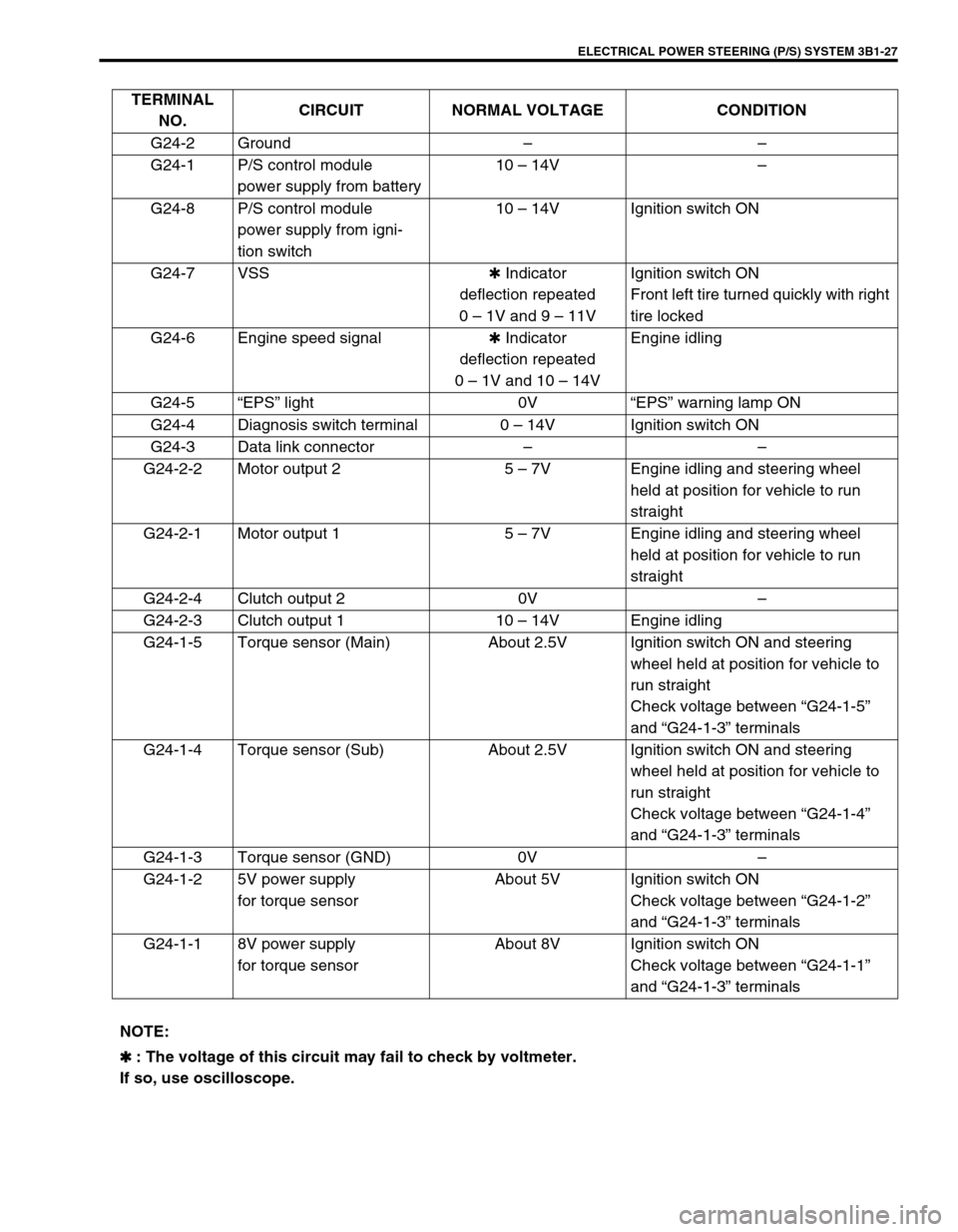
TERMINAL
NO.CIRCUIT NORMAL VOLTAGE CONDITION
G24-2 Ground––
G24-1 P/S control module
power supply from battery10 – 14V–
G24-8 P/S control module
power supply from igni-
tion switch10 – 14V Ignition switch ON
G24-7 VSS✱ Indicator
deflection repeated
0 – 1V and 9 – 11VIgnition switch ON
Front left tire turned quickly with right
tire locked
G24-6 Engine speed signal✱ Indicator
deflection repeated
0 – 1V and 10 – 14VEngine idling
G24-5“EPS” light 0V“EPS” warning lamp ON
G24-4 Diagnosis switch terminal 0 – 14V Ignition switch ON
G24-3 Data link connector––
G24-2-2 Motor output 2 5 – 7V Engine idling and steering wheel
held at position for vehicle to run
straight
G24-2-1 Motor output 1 5 – 7V Engine idling and steering wheel
held at position for vehicle to run
straight
G24-2-4 Clutch output 2 0V–
G24-2-3 Clutch output 1 10 – 14V Engine idling
G24-1-5 Torque sensor (Main) About 2.5V Ignition switch ON and steering
wheel held at position for vehicle to
run straight
Check voltage between “G24-1-5”
and “G24-1-3” terminals
G24-1-4 Torque sensor (Sub) About 2.5V Ignition switch ON and steering
wheel held at position for vehicle to
run straight
Check voltage between “G24-1-4”
and “G24-1-3” terminals
G24-1-3 Torque sensor (GND) 0V–
G24-1-2 5V power supply
for torque sensorAbout 5V Ignition switch ON
Check voltage between “G24-1-2”
and “G24-1-3” terminals
G24-1-1 8V power supply
for torque sensorAbout 8V Ignition switch ON
Check voltage between “G24-1-1”
and “G24-1-3” terminals
NOTE:
✱
✱✱ ✱ : The voltage of this circuit may fail to check by voltmeter.
If so, use oscilloscope.
Page 171 of 698
3B1-30 ELECTRICAL POWER STEERING (P/S) SYSTEM
MOTOR AND CLUTCH
ON-VEHICLE INSPECTION
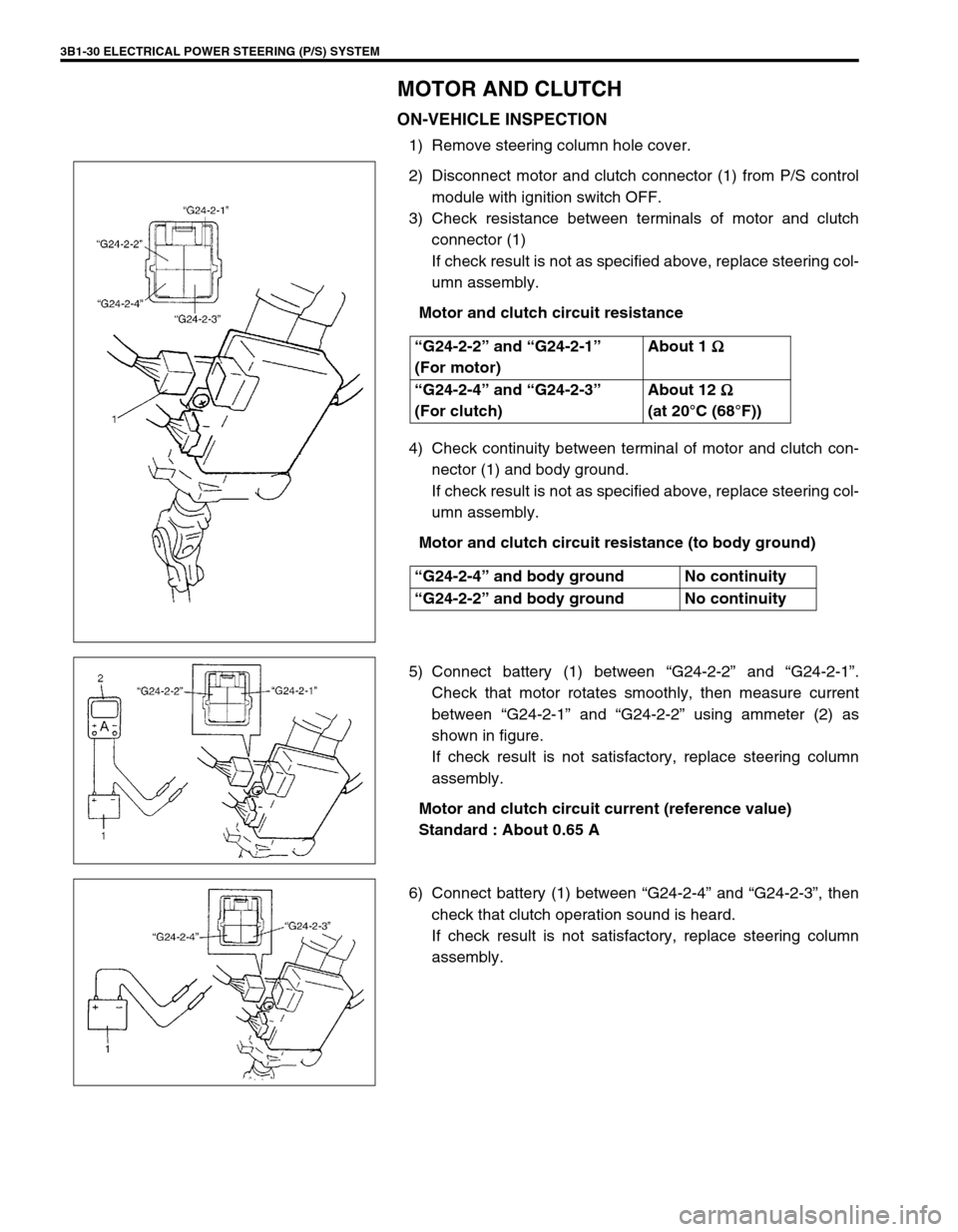
1) Remove steering column hole cover.
2) Disconnect motor and clutch connector (1) from P/S control
module with ignition switch OFF.
3) Check resistance between terminals of motor and clutch
connector (1)
If check result is not as specified above, replace steering col-
umn assembly.
Motor and clutch circuit resistance
4) Check continuity between terminal of motor and clutch con-
nector (1) and body ground.
If check result is not as specified above, replace steering col-
umn assembly.
Motor and clutch circuit resistance (to body ground)
5) Connect battery (1) between “G24-2-2” and “G24-2-1”.
Check that motor rotates smoothly, then measure current
between “G24-2-1” and “G24-2-2” using ammeter (2) as
shown in figure.
If check result is not satisfactory, replace steering column
assembly.
Motor and clutch circuit current (reference value)
Standard : About 0.65 A
6) Connect battery (1) between “G24-2-4” and “G24-2-3”, then
check that clutch operation sound is heard.
If check result is not satisfactory, replace steering column
assembly. “G24-2-2” and “G24-2-1”
(For motor)About 1
Ω
ΩΩ Ω
“G24-2-4” and “G24-2-3”
(For clutch)About 12
Ω
ΩΩ Ω
(at 20°C (68°F))
“G24-2-4” and body ground No continuity
“G24-2-2” and body ground No continuity
Page 388 of 698

ENGINE GENERAL INFORMATION AND DIAGNOSIS 6-19
P1451 Barometric pressure sen-
sor performance problemDifference between manifold absolute
pressure (MAP sensor value) and baro-
metric pressure (barometric pressure sen-
sor value) is larger than specification
during cranking.2 driving
cyclesNot
applicable
P1500 Starter signal circuit mal-
functionStarter signal is not inputted from engine
cranking till its start and after or it is always
inputted2 driving
cyclesNot
applicable
P1510 ECM backup power source
malfunctionNo backup power after starting engine 1 driving
cycleNot
applicable
P1600 Serial communication prob-
lem between ECM and
TCMNo signal or check sum error while engine
running1 driving
cycleNot
applicable
P1717 AT D-range signal circuit
malfunctionNo “D” range (park/neutral position signal)
is inputted while vehicle running2 driving
cyclesNot
applicable DTC
NO.DETECTING ITEM DETECTING CONDITION
(DTC will set when detecting :)MIL
(vehicle
with immo-
bilizer indi-
cator lamp)MIL
(vehicle
without
immobi-
lizer indica-
tor lamp)
DTC NO. DETECTING ITEM DETECTING CONDITION
(DTC will set when detecting :)MIL
✱P0702 Transmission Control System Electrical
Refer to Section 7B ✱P0705 Transmission Range Sensor Circuit Malfunc-
tion
✱P0710 Transmission Fluid Temperature Sensor Cir-
cuit Malfunction
✱P0715 Input/turbine Speed Sensor Circuit Malfunc-
tion
✱P0720 Output Shaft Speed Sensor Circuit Malfunc-
tion
✱P0725 Engine Speed Input Circuit Malfunction
✱P0730 Incorrect Gear Ratio
✱P0741 Torque Converter Clutch System Perfor-
mance or Stuck Off
✱P0743 Torque Converter Clutch System Electrical
✱P0753 Shift Solenoid A Electrical
✱P0758 Shift Solenoid B Electrical
✱P0763 Shift Solenoid C Electrical
✱P0768 Shift Solenoid D Electrical
✱P0773 Shift Solenoid E Electrical
✱P1700 Throttle Position Signal Input Malfunction
✱P1702 Internal Control Module Memory Check Some
Error
✱P1709 Engine Coolant Temperature Signal Input
Malfunction
Page 396 of 698
ENGINE GENERAL INFORMATION AND DIAGNOSIS 6-27
Engine noise
Note : Before
checking mechani-
cal noise, make sure
that :
Specified spark
plug is used.
Specified fuel is
used.Improper valve lash Valve lash in Section 6A1.
Worn valve stem and guide Valves inspection in Section 6A1.
Weak or broken valve spring Valve springs inspection in Section
6A1.
Warped or bent valve Valves inspection in Section 6A1.
Worn piston, ring and cylinder bore Pistons and cylinders inspection in Sec-
tion 6A1.
Worn rod bearing Crank pin and connecting rod bearing
inspection in Section 6A1.
Worn crank pin Crank pin and connecting rod bearing
inspection in Section 6A1.
Loose connecting rod nuts Connecting rod installation in Section
6A1.
Low oil pressure Previously outlined.
Low oil pressure Previously outlined.
Worn bearing Crankshaft and bearing inspection in
Section 6A1.
Worn crankshaft journal Crankshaft and bearing inspection in
Section 6A1.
Loose bearing cap bolts Crankshaft inspection in Section 6A1.
Excessive crankshaft thrust play Crankshaft thrust play inspection in
Section 6A1.
Overheating
Inoperative thermostat Thermostat in Section 6B.
Poor water pump performance Water pump in Section 6B.
Clogged or leaky radiator Radiator in Section 6B.
Improper engine oil grade Engine oil and oil filter change in Sec-
tion 0B.
Clogged oil filter or oil strainer Oil pressure check in Section 6A1.
Poor oil pump performance Oil pressure check in Section 6A1.
Faulty radiator fan control system Radiator fan control system in Section
6E1.
Dragging brakes Trouble diagnosis in Section 5.
Slipping clutch Trouble diagnosis in Section 7C.
Blown cylinder head gasket Cylinder head in Section 6A1. Condition Possible Cause Correction
Page 397 of 698
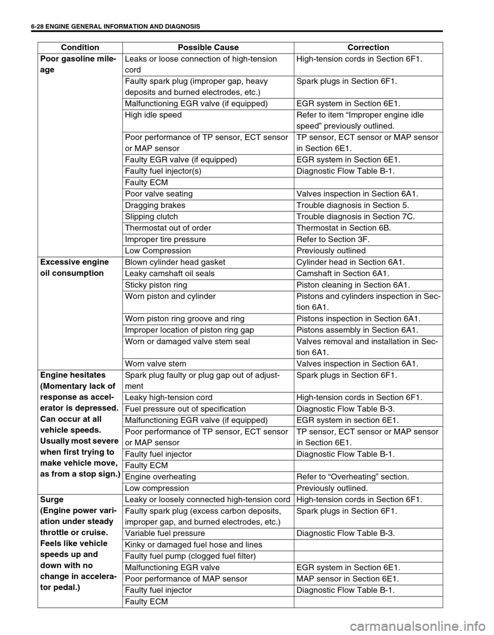
6-28 ENGINE GENERAL INFORMATION AND DIAGNOSIS
Poor gasoline mile-
age Leaks or loose connection of high-tension
cordHigh-tension cords in Section 6F1.
Faulty spark plug (improper gap, heavy
deposits and burned electrodes, etc.)Spark plugs in Section 6F1.
Malfunctioning EGR valve (if equipped) EGR system in Section 6E1.
High idle speed Refer to item “Improper engine idle
speed” previously outlined.
Poor performance of TP sensor, ECT sensor
or MAP sensorTP sensor, ECT sensor or MAP sensor
in Section 6E1.
Faulty EGR valve (if equipped) EGR system in Section 6E1.
Faulty fuel injector(s) Diagnostic Flow Table B-1.
Faulty ECM
Poor valve seating Valves inspection in Section 6A1.
Dragging brakes Trouble diagnosis in Section 5.
Slipping clutch Trouble diagnosis in Section 7C.
Thermostat out of order Thermostat in Section 6B.
Improper tire pressure Refer to Section 3F.
Low Compression Previously outlined
Excessive engine
oil consumption Blown cylinder head gasket Cylinder head in Section 6A1.
Leaky camshaft oil seals Camshaft in Section 6A1.
Sticky piston ring Piston cleaning in Section 6A1.
Worn piston and cylinder Pistons and cylinders inspection in Sec-
tion 6A1.
Worn piston ring groove and ring Pistons inspection in Section 6A1.
Improper location of piston ring gap Pistons assembly in Section 6A1.
Worn or damaged valve stem seal Valves removal and installation in Sec-
tion 6A1.
Worn valve stem Valves inspection in Section 6A1.
Engine hesitates
(Momentary lack of
response as accel-
erator is depressed.
Can occur at all
vehicle speeds.
Usually most severe
when first trying to
make vehicle move,
as from a stop sign.)Spark plug faulty or plug gap out of adjust-
mentSpark plugs in Section 6F1.
Leaky high-tension cord High-tension cords in Section 6F1.
Fuel pressure out of specification Diagnostic Flow Table B-3.
Malfunctioning EGR valve (if equipped) EGR system in section 6E1.
Poor performance of TP sensor, ECT sensor
or MAP sensorTP sensor, ECT sensor or MAP sensor
in Section 6E1.
Faulty fuel injector Diagnostic Flow Table B-1.
Faulty ECM
Engine overheating Refer to “Overheating” section.
Low compression Previously outlined.
Surge
(Engine power vari-
ation under steady
throttle or cruise.
Feels like vehicle
speeds up and
down with no
change in accelera-
tor pedal.)Leaky or loosely connected high-tension cord High-tension cords in Section 6F1.
Faulty spark plug (excess carbon deposits,
improper gap, and burned electrodes, etc.)Spark plugs in Section 6F1.
Variable fuel pressure Diagnostic Flow Table B-3.
Kinky or damaged fuel hose and lines
Faulty fuel pump (clogged fuel filter)
Malfunctioning EGR valve EGR system in Section 6E1.
Poor performance of MAP sensor MAP sensor in Section 6E1.
Faulty fuel injector Diagnostic Flow Table B-1.
Faulty ECM Condition Possible Cause Correction