Page 294 of 698
BRAKES 5-21
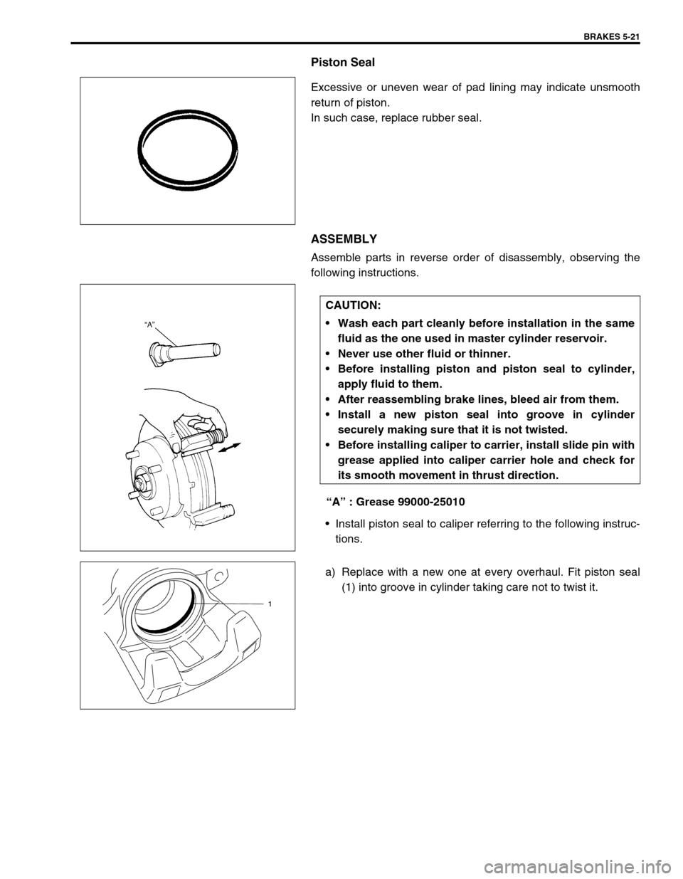
Piston Seal
Excessive or uneven wear of pad lining may indicate unsmooth
return of piston.
In such case, replace rubber seal.
ASSEMBLY
Assemble parts in reverse order of disassembly, observing the
following instructions.
“A” : Grease 99000-25010
Install piston seal to caliper referring to the following instruc-
tions.
a) Replace with a new one at every overhaul. Fit piston seal
(1) into groove in cylinder taking care not to twist it.
CAUTION:
Wash each part cleanly before installation in the same
fluid as the one used in master cylinder reservoir.
Never use other fluid or thinner.
Before installing piston and piston seal to cylinder,
apply fluid to them.
After reassembling brake lines, bleed air from them.
Install a new piston seal into groove in cylinder
securely making sure that it is not twisted.
Before installing caliper to carrier, install slide pin with
grease applied into caliper carrier hole and check for
its smooth movement in thrust direction.
1
Page 295 of 698
5-22 BRAKES
b) Before inserting piston (2) into cylinder, install boot (1) onto
piston as shown.
“A” : 1-grooved side directed cylinder side
“B” : 2-grooved side directed pad side
c) Fit boot as it is in figure into boot groove in cylinder with fin-
gers.
d) Insert piston into cylinder by hand and fit boot in boot
groove in piston.
INSTALLATION
1) Connect caliper to flexible hose.
2) Apply grease to slide pin, then install caliper to caliper car-
rier.
3) Torque caliper pin bolts (1) to specification.
Tightening torque
Caliper pin bolts (a) : 26 N·m (2.6 kg-m, 19.0 Ib-ft)
“A”
“B”
NOTE:
Check that boot is fitted in boot groove securely all
around piston.
NOTE:
Make sure that boots are fit into groove securely.
Page 296 of 698
BRAKES 5-23
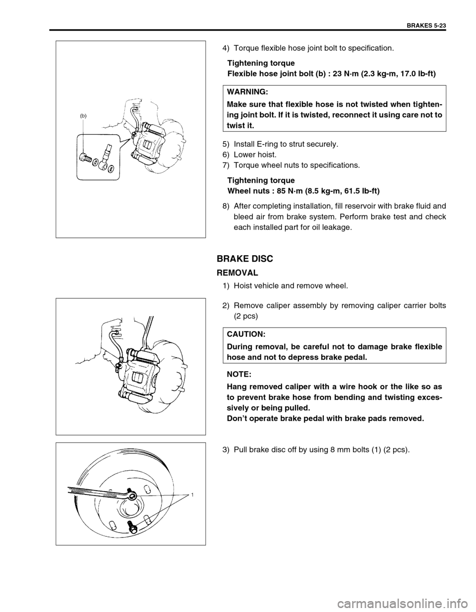
4) Torque flexible hose joint bolt to specification.
Tightening torque
Flexible hose joint bolt (b) : 23 N·m (2.3 kg-m, 17.0 Ib-ft)
5) Install E-ring to strut securely.
6) Lower hoist.
7) Torque wheel nuts to specifications.
Tightening torque
Wheel nuts : 85 N·m (8.5 kg-m, 61.5 Ib-ft)
8) After completing installation, fill reservoir with brake fluid and
bleed air from brake system. Perform brake test and check
each installed part for oil leakage.
BRAKE DISC
REMOVAL
1) Hoist vehicle and remove wheel.
2) Remove caliper assembly by removing caliper carrier bolts
(2 pcs)
3) Pull brake disc off by using 8 mm bolts (1) (2 pcs).WARNING:
Make sure that flexible hose is not twisted when tighten-
ing joint bolt. If it is twisted, reconnect it using care not to
twist it.
CAUTION:
During removal, be careful not to damage brake flexible
hose and not to depress brake pedal.
NOTE:
Hang removed caliper with a wire hook or the like so as
to prevent brake hose from bending and twisting exces-
sively or being pulled.
Don’t operate brake pedal with brake pads removed.
Page 304 of 698
BRAKES 5-31
INSTALLATION
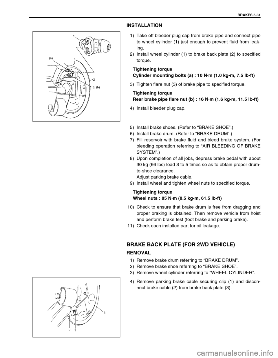
1) Take off bleeder plug cap from brake pipe and connect pipe
to wheel cylinder (1) just enough to prevent fluid from leak-
ing.
2) Install wheel cylinder (1) to brake back plate (2) to specified
torque.
Tightening torque
Cylinder mounting bolts (a) : 10 N·m (1.0 kg-m, 7.5 lb-ft)
3) Tighten flare nut (3) of brake pipe to specified torque.
Tightening torque
Rear brake pipe flare nut (b) : 16 N·m (1.6 kg-m, 11.5 lb-ft)
4) Install bleeder plug cap.
5) Install brake shoes. (Refer to “BRAKE SHOE”.)
6) Install brake drum. (Refer to “BRAKE DRUM”.)
7) Fill reservoir with brake fluid and bleed brake system. (For
bleeding operation referring to “AIR BLEEDING OF BRAKE
SYSTEM”.)
8) Upon completion of all jobs, depress brake pedal with about
30 kg (66 lbs) load 3 to 5 times so as to obtain proper drum-
to-shoe clearance.
Adjust parking brake cable.
9) Install wheel and tighten wheel nuts to specified torque.
Tightening torque
Wheel nuts : 85 N·m (8.5 kg-m, 61.5 lb-ft)
10) Check to ensure that brake drum is free from dragging and
proper braking is obtained. Then remove vehicle from hoist
and perform brake test (foot brake and parking brake).
11) Check each installed part for oil leakage.
BRAKE BACK PLATE (FOR 2WD VEHICLE)
REMOVAL
1) Remove brake drum referring to “BRAKE DRUM”.
2) Remove brake shoe referring to “BRAKE SHOE”.
3) Remove wheel cylinder referring to “WHEEL CYLINDER”.
4) Remove parking brake cable securing clip (1) and discon-
nect brake cable (2) from brake back plate (3).
Page 305 of 698
5-32 BRAKES
5) Remove brake back plate (1) by removing bolts (2).
INSTALLATION
1) Apply water tight sealant to mating surfaces of brake back
plate and rear axle.
“A” : Sealant 99000-31090
2) Install brake back plate and tighten back plate bolts to speci-
fied torque.
Tightening torque
Brake back plate bolts (a) : 23 N·m (2.3 kg-m, 17.0 lb-ft)
3) Apply water tight sealant where plate and cable contact, and
run parking brake cable (1) through brake back plate (2) and
secure it with clip (3).
“A” : Sealant 99000-31090
4) Install wheel cylinder, and tighten wheel cylinder bolts and
brake pipe flare nut to specified torque. (Refer to “WHEEL
CYLINDER”.)
5) For procedure hereafter referring to “WHEEL CYLINDER”.
A: Forward
Page 308 of 698
BRAKES 5-35
INSPECTION
1) Check all disassembled parts for wear and damage.
If anything faulty is found, replace.
2) Check screw hole in master cylinder for gall or corrosion.
If anything faulty is found, replace.
DISASSEMBLY
1) Loosen cap and remove it.
2) Remove component parts from master cylinder body.
ASSEMBLY
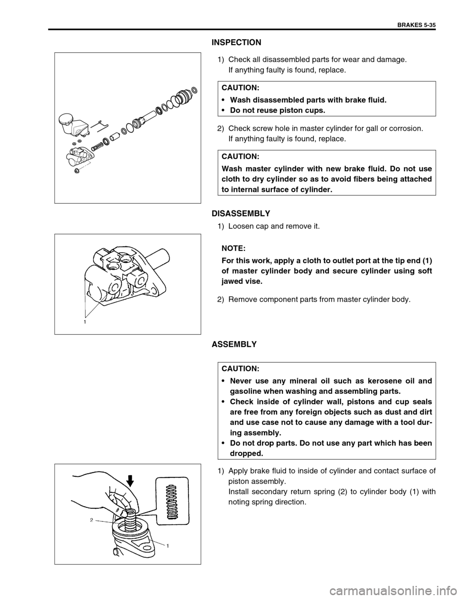
1) Apply brake fluid to inside of cylinder and contact surface of
piston assembly.
Install secondary return spring (2) to cylinder body (1) with
noting spring direction. CAUTION:
Wash disassembled parts with brake fluid.
Do not reuse piston cups.
CAUTION:
Wash master cylinder with new brake fluid. Do not use
cloth to dry cylinder so as to avoid fibers being attached
to internal surface of cylinder.
NOTE:
For this work, apply a cloth to outlet port at the tip end (1)
of master cylinder body and secure cylinder using soft
jawed vise.
CAUTION:
Never use any mineral oil such as kerosene oil and
gasoline when washing and assembling parts.
Check inside of cylinder wall, pistons and cup seals
are free from any foreign objects such as dust and dirt
and use case not to cause any damage with a tool dur-
ing assembly.
Do not drop parts. Do not use any part which has been
dropped.
Page 334 of 698
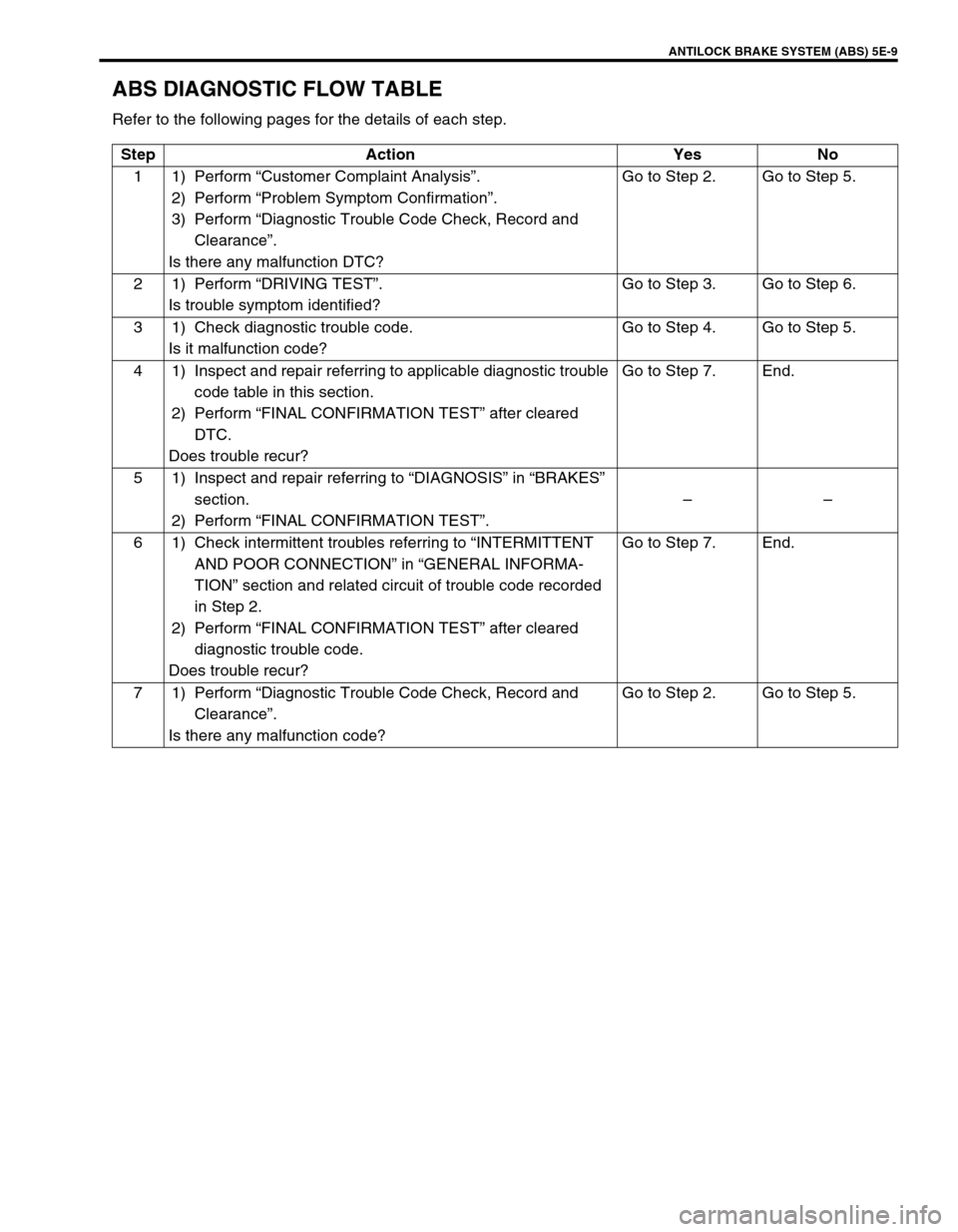
ANTILOCK BRAKE SYSTEM (ABS) 5E-9
ABS DIAGNOSTIC FLOW TABLE
Refer to the following pages for the details of each step.
Step Action Yes No
11)Perform “Customer Complaint Analysis”.
2) Perform “Problem Symptom Confirmation”.
3) Perform “Diagnostic Trouble Code Check, Record and
Clearance”.
Is there any malfunction DTC?Go to Step 2. Go to Step 5.
21)Perform “DRIVING TEST”.
Is trouble symptom identified?Go to Step 3. Go to Step 6.
3 1) Check diagnostic trouble code.
Is it malfunction code?Go to Step 4. Go to Step 5.
4 1) Inspect and repair referring to applicable diagnostic trouble
code table in this section.
2) Perform “FINAL CONFIRMATION TEST” after cleared
DTC.
Does trouble recur?Go to Step 7. End.
5 1) Inspect and repair referring to “DIAGNOSIS” in “BRAKES”
section.
2) Perform “FINAL CONFIRMATION TEST”.––
6 1) Check intermittent troubles referring to “INTERMITTENT
AND POOR CONNECTION” in “GENERAL INFORMA-
TION” section and related circuit of trouble code recorded
in Step 2.
2) Perform “FINAL CONFIRMATION TEST” after cleared
diagnostic trouble code.
Does trouble recur?Go to Step 7. End.
71)Perform “Diagnostic Trouble Code Check, Record and
Clearance”.
Is there any malfunction code?Go to Step 2. Go to Step 5.
Page 341 of 698
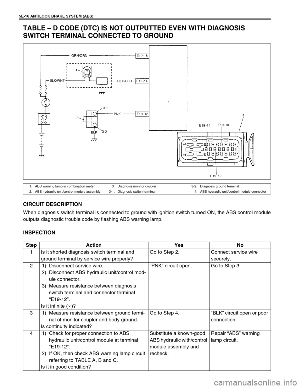
5E-16 ANTILOCK BRAKE SYSTEM (ABS)
TABLE – D CODE (DTC) IS NOT OUTPUTTED EVEN WITH DIAGNOSIS
SWITCH TERMINAL CONNECTED TO GROUND
CIRCUIT DESCRIPTION
When diagnosis switch terminal is connected to ground with ignition switch turned ON, the ABS control module
outputs diagnostic trouble code by flashing ABS warning lamp.
INSPECTION
1. ABS warning lamp in combination meter 3. Diagnosis monitor coupler 3-2. Diagnosis ground terminal
2. ABS hydraulic unit/control module assembly 3-1. Diagnosis switch terminal 4. ABS hydraulic unit/control module connector
Step Action Yes No
1 Is it shorted diagnosis switch terminal and
ground terminal by service wire properly?Go to Step 2. Connect service wire
securely.
2 1) Disconnect service wire.
2) Disconnect ABS hydraulic unit/control mod-
ule connector.
3) Measure resistance between diagnosis
switch terminal and connector terminal
“E19-12”.
Is it infinite (∞)?“PNK” circuit open. Go to Step 3.
3 1) Measure resistance between ground termi-
nal of monitor coupler and body ground.
Is continuity indicated?Go to Step 4.“BLK” circuit open or poor
connection.
4 1) Check for proper connection to ABS
hydraulic unit/control module at terminal
“E19-12”.
2) If OK, then check ABS warning lamp circuit
referring to TABLE A, B and C.
Is it in good condition?Substitute a known-good
ABS hydraulic with/control
module assembly and
recheck.Repair “ABS” warning
lamp circuit.