Page 620 of 698
ENGINE FUEL 6C-13
INSTALLATION
1) Clean mating surfaces of fuel pump assembly (1) and fuel
tank.
2) Put plate (2) on fuel pump assembly (1) by matching the pro-
trusion of fuel pump assembly (3) to plate hole (4) as shown.
3) Install new gasket (2) and fuel pump assembly (1) with plate
(3) to fuel tank.
Tightening torque
Fuel pump assembly bolts (a) : 10 N·m (1.0 kg-m, 7.5 lb-ft)
4) Connect fuel breather hose (1), fuel vapor hose (2) and fuel
feed line (3) (pipe joint) to fuel pump assembly.
5) Install fuel tank (1) to vehicle. Refer to “FUEL TANK” in this
section.
3 2
4 43
1
3
1
2
(a)
CAUTION:
When connecting joint, clean outside surface of pipe
where joint is to be inserted, push joint into pipe till joint
lock clicks and check to ensure that pipes are connected
securely, or fuel leak may occur.1
23
Page 636 of 698
ENGINE AND EMISSION CONTROL SYSTEM 6E1-15
ON-VEHICLE SERVICE
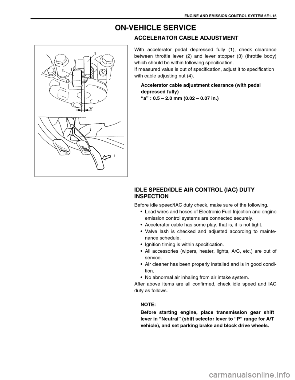
ACCELERATOR CABLE ADJUSTMENT
With accelerator pedal depressed fully (1), check clearance
between throttle lever (2) and lever stopper (3) (throttle body)
which should be within following specification.
If measured value is out of specification, adjust it to specification
with cable adjusting nut (4).
Accelerator cable adjustment clearance (with pedal
depressed fully)
“a” : 0.5 – 2.0 mm (0.02 – 0.07 in.)
IDLE SPEED/IDLE AIR CONTROL (IAC) DUTY
INSPECTION
Before idle speed/IAC duty check, make sure of the following.
Lead wires and hoses of Electronic Fuel Injection and engine
emission control systems are connected securely.
Accelerator cable has some play, that is, it is not tight.
Valve lash is checked and adjusted according to mainte-
nance schedule.
Ignition timing is within specification.
All accessories (wipers, heater, lights, A/C, etc.) are out of
service.
Air cleaner has been properly installed and is in good condi-
tion.
No abnormal air inhaling from air intake system.
After above items are all confirmed, check idle speed and IAC
duty as follows.
NOTE:
Before starting engine, place transmission gear shift
lever in “Neutral” (shift selector lever to “P” range for A/T
vehicle), and set parking brake and block drive wheels.
Page 641 of 698
6E1-20 ENGINE AND EMISSION CONTROL SYSTEM
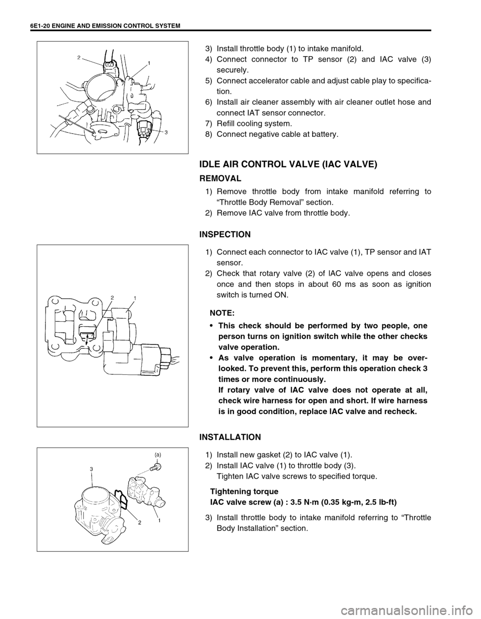
3) Install throttle body (1) to intake manifold.
4) Connect connector to TP sensor (2) and IAC valve (3)
securely.
5) Connect accelerator cable and adjust cable play to specifica-
tion.
6) Install air cleaner assembly with air cleaner outlet hose and
connect IAT sensor connector.
7) Refill cooling system.
8) Connect negative cable at battery.
IDLE AIR CONTROL VALVE (IAC VALVE)
REMOVAL
1) Remove throttle body from intake manifold referring to
“Throttle Body Removal” section.
2) Remove IAC valve from throttle body.
INSPECTION
1) Connect each connector to IAC valve (1), TP sensor and IAT
sensor.
2) Check that rotary valve (2) of lAC valve opens and closes
once and then stops in about 60 ms as soon as ignition
switch is turned ON.
INSTALLATION
1) Install new gasket (2) to IAC valve (1).
2) Install IAC valve (1) to throttle body (3).
Tighten IAC valve screws to specified torque.
Tightening torque
IAC valve screw (a) : 3.5 N·m (0.35 kg-m, 2.5 lb-ft)
3) Install throttle body to intake manifold referring to “Throttle
Body Installation” section.
NOTE:
This check should be performed by two people, one
person turns on ignition switch while the other checks
valve operation.
As valve operation is momentary, it may be over-
looked. To prevent this, perform this operation check 3
times or more continuously.
If rotary valve of lAC valve does not operate at all,
check wire harness for open and short. If wire harness
is in good condition, replace lAC valve and recheck.
Page 642 of 698
ENGINE AND EMISSION CONTROL SYSTEM 6E1-21
FUEL DELIVERY SYSTEM
FUEL PRESSURE INSPECTION
1) Relieve fuel pressure in fuel feed line referring to “Fuel Pres-
sure Relief Procedure” in Section 6.
2) Disconnect fuel feed hose from fuel delivery pipe.
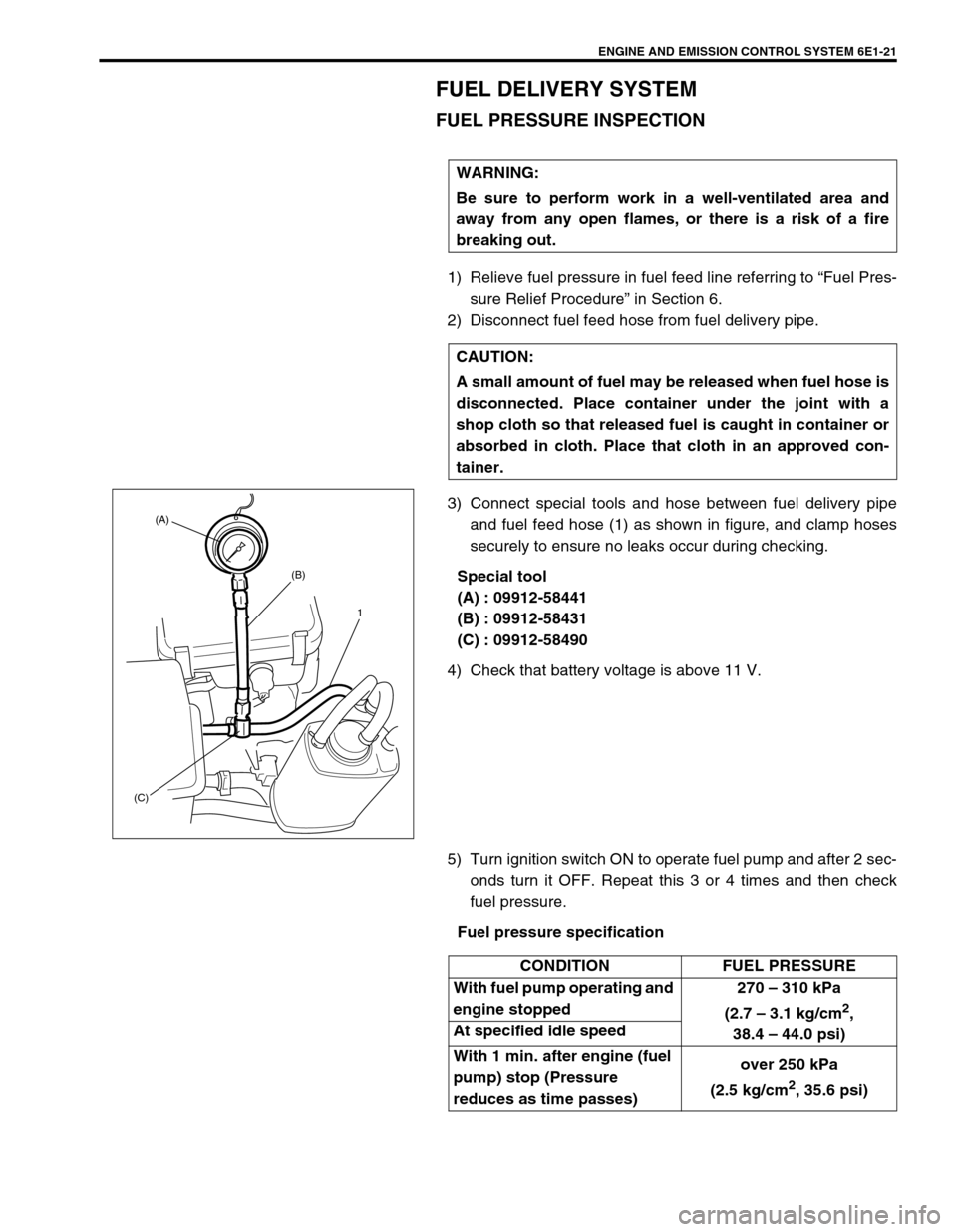
3) Connect special tools and hose between fuel delivery pipe
and fuel feed hose (1) as shown in figure, and clamp hoses
securely to ensure no leaks occur during checking.
Special tool
(A) : 09912-58441
(B) : 09912-58431
(C) : 09912-58490
4) Check that battery voltage is above 11 V.
5) Turn ignition switch ON to operate fuel pump and after 2 sec-
onds turn it OFF. Repeat this 3 or 4 times and then check
fuel pressure.
Fuel pressure specification WARNING:
Be sure to perform work in a well-ventilated area and
away from any open flames, or there is a risk of a fire
breaking out.
CAUTION:
A small amount of fuel may be released when fuel hose is
disconnected. Place container under the joint with a
shop cloth so that released fuel is caught in container or
absorbed in cloth. Place that cloth in an approved con-
tainer.
(A)
(B)
(C)1
CONDITION FUEL PRESSURE
With fuel pump operating and
engine stopped270 – 310 kPa
(2.7 – 3.1 kg/cm
2,
38.4 – 44.0 psi) At specified idle speed
With 1 min. after engine (fuel
pump) stop (Pressure
reduces as time passes)over 250 kPa
(2.5 kg/cm
2, 35.6 psi)
Page 643 of 698
6E1-22 ENGINE AND EMISSION CONTROL SYSTEM
6) Start engine and warm it up to normal operating tempera-
ture.
7) Measure fuel pressure at idling.
If measured pressure does not satisfy specification, refer to
“Diagnostic Flow Table B-3” in “Engine Diagnosis” section
and check each possibly defective part. Replace if found
defective.
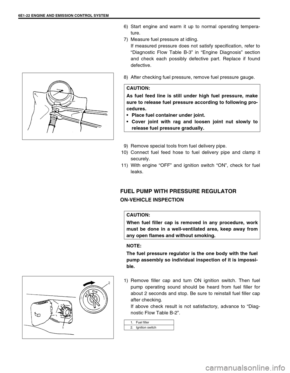
8) After checking fuel pressure, remove fuel pressure gauge.
9) Remove special tools from fuel delivery pipe.
10) Connect fuel feed hose to fuel delivery pipe and clamp it
securely.
11) With engine “OFF” and ignition switch “ON”, check for fuel
leaks.
FUEL PUMP WITH PRESSURE REGULATOR
ON-VEHICLE INSPECTION
1) Remove filler cap and turn ON ignition switch. Then fuel
pump operating sound should be heard from fuel filler for
about 2 seconds and stop. Be sure to reinstall fuel filler cap
after checking.
If above check result is not satisfactory, advance to “Diag-
nostic Flow Table B-2”. CAUTION:
As fuel feed line is still under high fuel pressure, make
sure to release fuel pressure according to following pro-
cedures.
Place fuel container under joint.
Cover joint with rag and loosen joint nut slowly to
release fuel pressure gradually.
CAUTION:
When fuel filler cap is removed in any procedure, work
must be done in a well-ventilated area, keep away from
any open flames and without smoking.
NOTE:
The fuel pressure regulator is the one body with the fuel
pump assembly so individual inspection of it is impossi-
ble.
1. Fuel filler
2. Ignition switch
Page 644 of 698
ENGINE AND EMISSION CONTROL SYSTEM 6E1-23
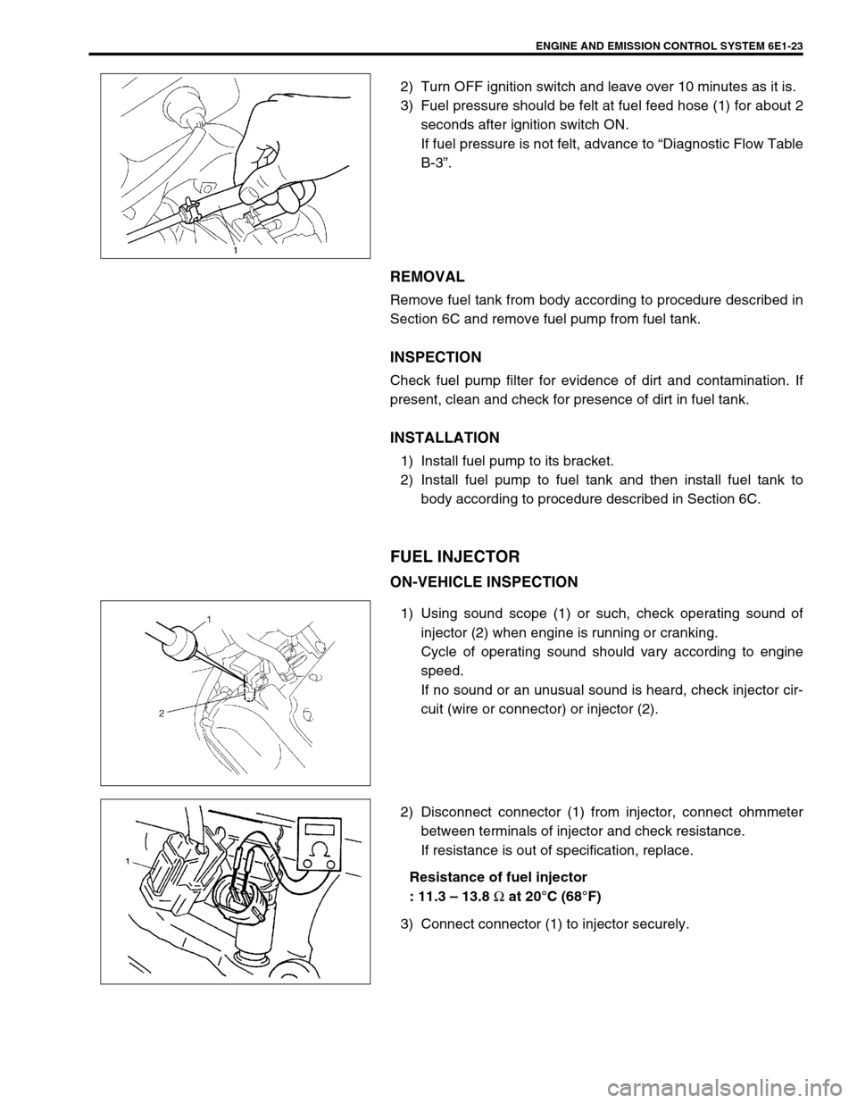
2) Turn OFF ignition switch and leave over 10 minutes as it is.
3) Fuel pressure should be felt at fuel feed hose (1) for about 2
seconds after ignition switch ON.
If fuel pressure is not felt, advance to “Diagnostic Flow Table
B-3”.
REMOVAL
Remove fuel tank from body according to procedure described in
Section 6C and remove fuel pump from fuel tank.
INSPECTION
Check fuel pump filter for evidence of dirt and contamination. If
present, clean and check for presence of dirt in fuel tank.
INSTALLATION
1) Install fuel pump to its bracket.
2) Install fuel pump to fuel tank and then install fuel tank to
body according to procedure described in Section 6C.
FUEL INJECTOR
ON-VEHICLE INSPECTION
1) Using sound scope (1) or such, check operating sound of
injector (2) when engine is running or cranking.
Cycle of operating sound should vary according to engine
speed.
If no sound or an unusual sound is heard, check injector cir-
cuit (wire or connector) or injector (2).
2) Disconnect connector (1) from injector, connect ohmmeter
between terminals of injector and check resistance.
If resistance is out of specification, replace.
Resistance of fuel injector
: 11.3 – 13.8
Ω at 20°C (68°F)
3) Connect connector (1) to injector securely.
Page 648 of 698
ENGINE AND EMISSION CONTROL SYSTEM 6E1-27
ELECTRONIC CONTROL SYSTEM
ENGINE CONTROL MODULE (ECM)
REMOVAL
1) Disconnect battery negative cable at battery.
2) Disable air bag system, referring to “Disabling The Air Bag
System” in Section 10B if equipped.
3) Disconnect ECM (1) and TCM (2) (if equipped) connectors.
4) Remove bolt and nuts, remove ECM and TCM (if equipped).
INSTALLATION
Reverse removal procedure noting the following:
Connect connectors to ECM and TCM (if equipped) securely.
MANIFOLD ABSOLUTE PRESSURE SENSOR (MAP
SENSOR)
INSPECTION
Check MAP sensor referring to “MAP Sensor Individual Check” in
DTC P0105 (No.11) Flow Table. If malfunction is found, replace.CAUTION:
As ECM consists of precision parts, be careful not to
expose it to excessive shock.
2
1
Page 649 of 698
6E1-28 ENGINE AND EMISSION CONTROL SYSTEM
THROTTLE POSITION SENSOR (TP SENSOR)
INSPECTION
1) Disconnect negative cable at battery and connector from IAT
sensor.
2) Remove air cleaner assembly with air cleaner outlet hose
and disconnect TP sensor connector.
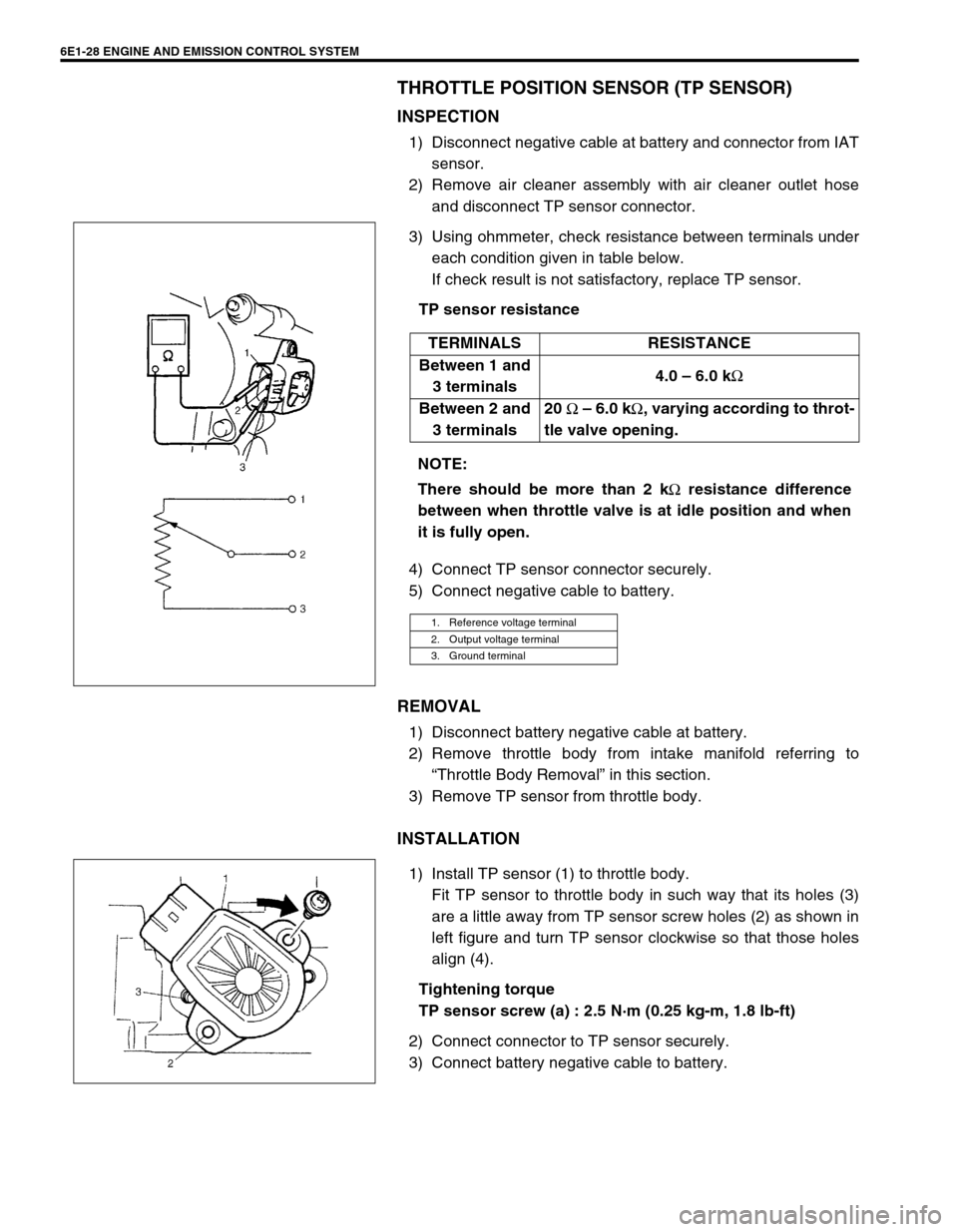
3) Using ohmmeter, check resistance between terminals under
each condition given in table below.
If check result is not satisfactory, replace TP sensor.
TP sensor resistance
4) Connect TP sensor connector securely.
5) Connect negative cable to battery.
REMOVAL
1) Disconnect battery negative cable at battery.
2) Remove throttle body from intake manifold referring to
“Throttle Body Removal” in this section.
3) Remove TP sensor from throttle body.
INSTALLATION
1) Install TP sensor (1) to throttle body.
Fit TP sensor to throttle body in such way that its holes (3)
are a little away from TP sensor screw holes (2) as shown in
left figure and turn TP sensor clockwise so that those holes
align (4).
Tightening torque
TP sensor screw (a) : 2.5 N·m (0.25 kg-m, 1.8 lb-ft)
2) Connect connector to TP sensor securely.
3) Connect battery negative cable to battery.TERMINALS RESISTANCE
Between 1 and
3 terminals4.0 – 6.0 k
Ω
Between 2 and
3 terminals20
Ω – 6.0 k
Ω, varying according to throt-
tle valve opening.
NOTE:
There should be more than 2 k
Ω resistance difference
between when throttle valve is at idle position and when
it is fully open.
1. Reference voltage terminal
2. Output voltage terminal
3. Ground terminal