Page 556 of 698

ENGINE MECHANICAL (M13 ENGINE) 6A1-55
7) Install valve spring and spring retainer.
Each valve spring has top end (large-pitch end (1)) and bot-
tom end (small-pitch end (2)). Be sure to position spring in
place with its bottom end (small-pitch end) facing the bottom
(valve spring seat side).
8) Using special tools (Valve lifter), compress valve spring and
fit two valve cotters (1) into groove in valve stem.
Special tool
(A) : 09916-14510
(B) : 09916-14910
(C) : 09916-84511
9) Install intake manifold, injectors and exhaust manifold to cyl-
inder head.
INSTALLATION
1) Clean mating surface of cylinder head and cylinder block.
Remove oil, old gasket and dust from mating surface.
2) Install knock pins (1) to cylinder block.
3) Install new cylinder head gasket (2) to cylinder block.
“TOP” mark provided on gasket comes to crankshaft pulley
side, facing up (toward cylinder head side).
4) Make sure that oil jet (venturi plug) (1) is installed and if it is,
that it is not clogged.
When installing it, be sure to tighten to specified torque.
Tightening torque
Venturi plug (a) : 5 N·m (0.5 kg-m, 3.5 lb-ft)
A : Valve spring retainer side
B : Valve spring seat side
NOTE:
When compressing the valve spring, be carefully to free
from damage in inside face of tappet installing hole.
Page 557 of 698

6A1-56 ENGINE MECHANICAL (M13 ENGINE)
5) Install cylinder head to cylinder block.
Apply engine oil to new cylinder head bolts and tighten them
gradually as follows.
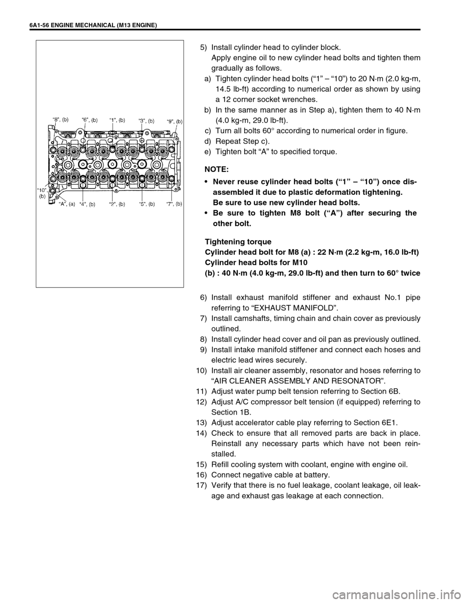
a) Tighten cylinder head bolts (“1” – “10”) to 20 N·m (2.0 kg-m,
14.5 lb-ft) according to numerical order as shown by using
a 12 corner socket wrenches.
b) In the same manner as in Step a), tighten them to 40 N·m
(4.0 kg-m, 29.0 lb-ft).
c) Turn all bolts 60° according to numerical order in figure.
d) Repeat Step c).
e) Tighten bolt “A” to specified torque.
Tightening torque
Cylinder head bolt for M8 (a) : 22 N·m (2.2 kg-m, 16.0 lb-ft)
Cylinder head bolts for M10
(b) : 40 N·m (4.0 kg-m, 29.0 lb-ft) and then turn to 60° twice
6) Install exhaust manifold stiffener and exhaust No.1 pipe
referring to “EXHAUST MANIFOLD”.
7) Install camshafts, timing chain and chain cover as previously
outlined.
8) Install cylinder head cover and oil pan as previously outlined.
9) Install intake manifold stiffener and connect each hoses and
electric lead wires securely.
10) Install air cleaner assembly, resonator and hoses referring to
“AIR CLEANER ASSEMBLY AND RESONATOR”.
11) Adjust water pump belt tension referring to Section 6B.
12) Adjust A/C compressor belt tension (if equipped) referring to
Section 1B.
13) Adjust accelerator cable play referring to Section 6E1.
14) Check to ensure that all removed parts are back in place.
Reinstall any necessary parts which have not been rein-
stalled.
15) Refill cooling system with coolant, engine with engine oil.
16) Connect negative cable at battery.
17) Verify that there is no fuel leakage, coolant leakage, oil leak-
age and exhaust gas leakage at each connection. NOTE:
Never reuse cylinder head bolts (“1” – “10”) once dis-
assembled it due to plastic deformation tightening.
Be sure to use new cylinder head bolts.
Be sure to tighten M8 bolt (“A”) after securing the
other bolt.
Page 558 of 698

ENGINE MECHANICAL (M13 ENGINE) 6A1-57
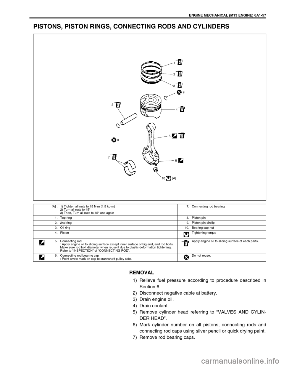
PISTONS, PISTON RINGS, CONNECTING RODS AND CYLINDERS
REMOVAL
1) Relieve fuel pressure according to procedure described in
Section 6.
2) Disconnect negative cable at battery.
3) Drain engine oil.
4) Drain coolant.
5) Remove cylinder head referring to “VALVES AND CYLIN-
DER HEAD”.
6) Mark cylinder number on all pistons, connecting rods and
connecting rod caps using silver pencil or quick drying paint.
7) Remove rod bearing caps.
[A] : 1) Tighten all nuts to 15 N·m (1.5 kg-m)
2) Turn all nuts to 45°
3) Then, Turn all nuts to 45° one again7. Connecting rod bearing
1. Top ring8. Piston pin
2. 2nd ring9. Piston pin circlip
3. Oil ring10. Bearing cap nut
4. PistonTightening torque
5. Connecting rod
: Apply engine oil to sliding surface except inner surface of big end, and rod bolts.
Make sure rod bolt diameter when reuse it due to plastic deformation tightening.
Refer to “INSPECTION” of “CONNECTING ROD”.Apply engine oil to sliding surface of each parts.
6. Connecting rod bearing cap
: Point arrow mark on cap to crankshaft pulley side.Do not reuse.
Page 559 of 698
6A1-58 ENGINE MECHANICAL (M13 ENGINE)
8) Install guide hose (1) over threads of rod bolts.
This prevents damage to bearing journal and rod bolt
threads when removing connecting rod.
9) Decarbonize top of cylinder bore before removing piston
from cylinder.
10) Push piston and connecting rod assembly out through the
top of cylinder bore.
DISASSEMBLY
1) Using piston ring expander, remove two compression rings
(Top and 2nd) and oil ring from piston.
2) Remove piston pin from connecting rod.
Ease out piston pin circlips (1), as shown.
Force piston pin out.
CLEANING
Decarbonize piston head and ring grooves, using a suitable tool.
INSPECTION
Cylinder
Inspect cylinder walls for scratches, roughness or ridges
which indicate excessive wear. If cylinder bore is very rough
or deeply scratched or ridged, rebore cylinder and use over-
size piston.
Page 560 of 698

ENGINE MECHANICAL (M13 ENGINE) 6A1-59
Using a cylinder gauge (1), measure cylinder bore in thrust
and axial directions at two positions (“a” and “b”) as shown in
figure.
If any of the following conditions is noted, rebore cylinder.
1) Cylinder bore dia. exceeds limit.
2) Difference of measurements at two positions exceeds taper
limit.
3) Difference between thrust and axial measurements exceeds
out-of-round limit.
Cylinder bore diameter
Limit : 78.15 mm (3.077 in.)
Cylinder taper and out-of-round
Limit : 0.10 mm (0.004 in.)
Pistons
Inspect piston for faults, cracks or other damaged.
Damaged or faulty piston should be replaced.
Piston diameter :
As indicated in figure, piston diameter should be measured
at a position 19.5 mm (0.77 in.) from piston skirt end in the
direction perpendicular to piston pin.
Piston diameter specification
“a” : 50 mm (1.96 in.)
“b” : 95 mm (3.74 in.)
NOTE:
If any one of four cylinders has to be rebored, rebore all
four to the same next oversize. This is necessary for the
sake of uniformity and balance.
Standard size77.953 – 77.968 mm
(3.0690 – 3.0696 in.)
with coating
77.969 – 77.984 mm
(3.0696 – 3.0702 in.)
Oversize
0.25 mm (0.0098 in.)78.203 – 78.218 mm
(3.0789 – 3.0794 in.)
Oversize
0.50 mm (0.0196 in.)78.453 – 78.468 mm
(3.0887 – 3.0893 in.)
“a” : 19.5 mm (0.77 in.)
Page 561 of 698

6A1-60 ENGINE MECHANICAL (M13 ENGINE)
Piston clearance:
Measure cylinder bore diameter and piston diameter to find
their difference which is piston clearance. Piston clearance
should be within specification as given below. If it is out of
specification, rebore cylinder and use oversize piston.
Piston clearance
: 0.032 – 0.061 mm (0.0013 – 0.0024 in.)
: 0.016 – 0.045 mm (0.0006 – 0.0018 in.) with coating
Ring groove clearance:
Before checking, piston grooves must be clean, dry and free
of carbon deposits.
Fit new piston ring (1) into piston groove, and measure clear-
ance between ring and ring land by using thickness gauge
(2). If clearance is out of limit, replace piston.
Ring groove clearance
Top ring
Standard : 0.03 – 0.07 mm (0.0012 – 0.0028 in.)
Limit : 0.12 mm (0.0047 in.)
2nd ring
Standard : 0.02 – 0.06 mm (0.0008 – 0.0024 in.)
Limit : 0.10 mm (0.0039 in.)
Oil ring
Standard : 0.03 – 0.17 mm (0.0012 – 0.0067 in.)
Piston Pin
Check piston pin, connecting rod small end bore and piston
bore for wear or damage, paying particular attention to con-
dition of small end bore bush. If pin, connecting rod small
end bore or piston bore is badly worn or damaged, replace
pin, connecting rod and/or piston. NOTE:
Cylinder bore diameters used here are measured in
thrust direction at two positions.
“a” : 19.5 mm (0.77 in.)
Page 562 of 698

ENGINE MECHANICAL (M13 ENGINE) 6A1-61
Piston pin clearance :
Check piston pin clearance in small end and piston. Replace
connecting rod and/or piston if its small end is badly worn or
damaged or if measured clearance exceeds limit.
Piston pin clearance in connecting rod small end
: 0.003 – 0.014 mm (0.0001 – 0.0006 in.)
Piston pin clearance in piston
: 0.006 – 0.017 mm (0.00026 – 0.00067 in.)
Small-end bore
: 20.003 – 20.011 mm (0.7875 – 0.7878 in.)
Piston pin dia.
: 19.997 – 20.000 mm (0.7873 – 0.7874 in.)
Piston bore
: 20.006 – 20.014 mm (0.7870 – 0.7874 in.)
Piston Rings
To measure end gap, insert piston ring (1) into cylinder bore and
then measure the gap by using thickness gauge (2).
If measured gap is out of specification, replace ring.
Piston ring end gap
Connecting Rod
Big-end side clearance:
Check big-end of connecting rod for side clearance, with rod
fitted and connected to its crank pin in the normal manner. If
measured clearance is found to exceed its limit, replace con-
necting rod.
Big-end side clearance
Standard : 0.25 - 0.40 mm (0.0098 - 0.0157 in.)
Limit : 0.35 mm (0.0138 in.)
NOTE:
Decarbonize and clean top of cylinder bore before insert-
ing piston ring.
Item Standard Limit
Top ring0.20 – 0.35 mm
(0.0079 – 0.0138 in.)0.7 mm
(0.0276 in.)
2nd ring0.30 – 0.45 mm
(0.0118 – 0.0177 in.)1.0 mm
(0.0039 in.)
Oil ring0.20 – 0.70 mm
(0.0079 – 0.0276 in.)1.5 mm
(0.059 in.)
“a” : 120 mm (4.72 in.)
Page 563 of 698

6A1-62 ENGINE MECHANICAL (M13 ENGINE)
Connecting rod alignment :
Mount connecting rod on aligner to check it for bow and
twist. If limit is exceeded, replace it.
Connecting rod alignment
Limit on bow : 0.05 mm (0.0020 in.)
Limit on twist : 0.10 mm (0.0039 in.)
Connecting rod bolt deformation (Plastic deformation tight-
ening bolt)
Measure connecting rod (1) bolt (2) for diameter “A” on 32
mm (1.25 in.) from bolt mounting surface and diameter “B”
on 40 mm (1.57 in.) from bolt mounting surface by using a
micrometer (3).
Bolt diameter difference should be specification as given
below. If it is out of specification, replace connecting rod.
Connecting rod bolt diameter difference
limit (“A” – “B”) : 0.1 mm (0.004 in.)
Connecting rod bolt measurement distance
“a” : 32 mm (1.25 in.)
“b” : 40 mm (1.57 in.)
Crank Pin and Connecting Rod Bearings
Inspect crank pin for uneven wear or damage. Measure
crank pin for out-of-round or taper with a micrometer. If crank
pin is damaged or out-of round or taper is out of limit, replace
crankshaft or regrind crank pin to undersize and use under-
size bearing.
Crank pin diameter
Crank pin taper and out-of-round
Limit : 0.01 mm (0.0004 in.)
Out-of-round : A – B
Taper : a – b
Connecting rod
bearing sizeCrank pin diameter
Standard41.982 – 42.000 mm
(1.6528 – 1.6535 in.)
Undersize
0.25 mm (0.0098 in.)41.732 – 41.750 mm
(1.6430 – 1.6437 in.)