Page 564 of 698

ENGINE MECHANICAL (M13 ENGINE) 6A1-63
Rod bearing :
Inspect bearing shells for signs of fusion, pitting, burn or flak-
ing and observe contact pattern. Bearing shells found in
defective condition must be replaced.
Two kinds of rod bearing are available; standard size bearing
and 0.25 mm (0.0098 in.) undersize bearing. For identifica-
tion of undersize bearing, it is painted red at the position as
indicated in figure, undersize bearing thickness is 1.605 –
1.615 mm (0.0632 – 0.0635 in.) at the center of it.
Rod bearing clearance :
1) Before checking bearing clearance, clean bearing and crank
pin.
2) Install bearing in connecting rod and bearing cap.
3) Place a piece of gaging plastic (1) to full width of crank pin as
contacted by bearing (parallel to crankshaft), avoiding oil
hole.
4) Install rod bearing cap (1) to connecting rod.
When installing cap, be sure to point arrow mark (2) on cap
to crankshaft pulley side, as shown in figure. After applying
engine oil to rod bolts and tighten cap nuts (3) gradually as
follows.
a) Tighten all cap nuts to 15 N·m (1.5 kg-m, 11.0 lb-ft).
b) Retighten them to 45°.
c) Repeat step b) once again.
Tightening torque
Connecting rod bearing cap nuts
(a) : 15 N·m (1.5 kg-m, 11.0 lb-ft) and extra tighten 90°
5) Remove cap and using a scale (1) on gaging plastic (2)
envelope, measure gaging plastic width at the widest point
(clearance).
If clearance exceeds its limit, use a new standard size bear-
ing and remeasure clearance.
Connecting rod bearing clearance
Standard : 0.029 – 0.047 mm (0.0011 – 0.0019 in.)
Limit : 0.065 mm (0.0026 in.)
1. Red paint
Page 565 of 698

6A1-64 ENGINE MECHANICAL (M13 ENGINE)
6) If clearance can not be brought to within its limit even by
using a new standard size bearing, regrind crankpin to
undersize and use 0.25 mm undersize bearing.
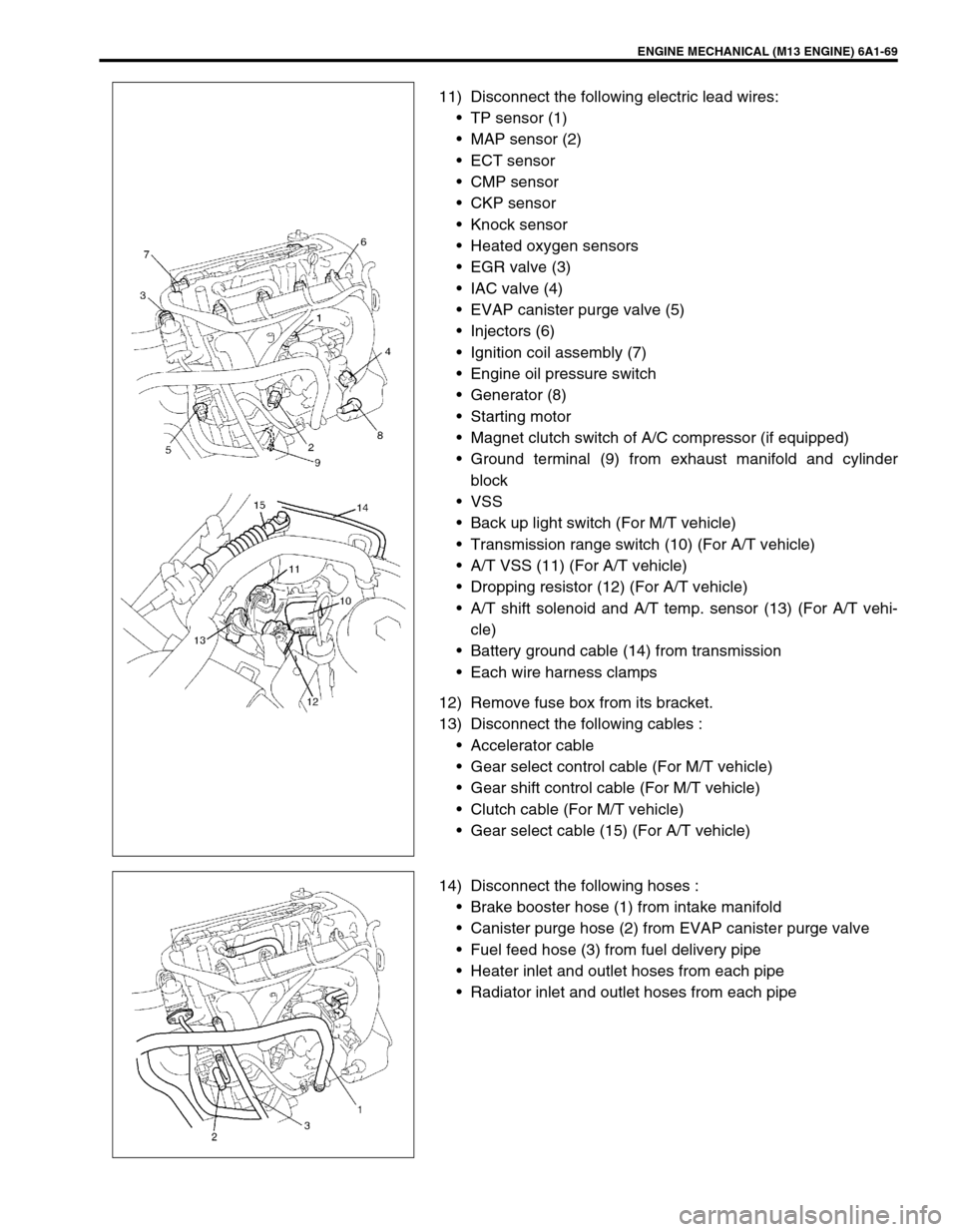
ASSEMBLY
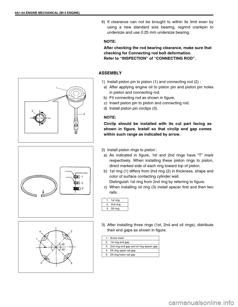
1) Install piston pin to piston (1) and connecting rod (2) :
a) After applying engine oil to piston pin and piston pin holes
in piston and connecting rod.
b) Fit connecting rod as shown in figure.
c) Insert piston pin to piston and connecting rod.
d) Install piston pin circlips (3).
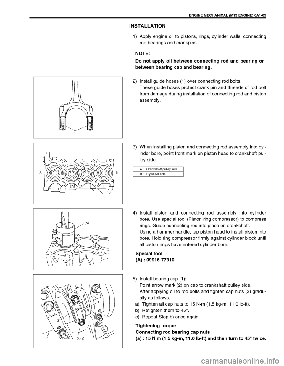
2) Install piston rings to piston :
a) As indicated in figure, 1st and 2nd rings have “T” mark
respectively. When installing these piston rings to piston,
direct marked side of each ring toward top of piston.
b) 1st ring (1) differs from 2nd ring (2) in thickness, shape and
color of surface contacting cylinder wall.
Distinguish 1st ring from 2nd ring by referring to figure.
c) When installing oil ring (3) install spacer first and then two
rails.
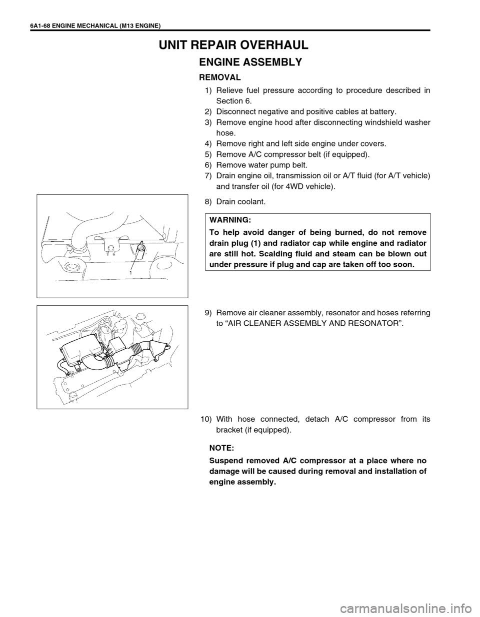
3) After installing three rings (1st, 2nd and oil rings), distribute
their end gaps as shown in figure. NOTE:
After checking the rod bearing clearance, make sure that
checking for Connecting rod bolt deformation.
Refer to “INSPECTION” of “CONNECTING ROD”.
NOTE:
Circlip should be installed with its cut part facing as
shown in figure. Install so that circlip end gap comes
within such range as indicated by arrow.
1. 1st ring
2. 2nd ring
3. Oil ring
1. Arrow mark
2. 1st ring end gap
3. 2nd ring end gap and oil ring spacer gap
4. Oil ring upper rail gap
5. Oil ring lower rail gap
Page 566 of 698

ENGINE MECHANICAL (M13 ENGINE) 6A1-65
INSTALLATION
1) Apply engine oil to pistons, rings, cylinder walls, connecting
rod bearings and crankpins.
2) Install guide hoses (1) over connecting rod bolts.
These guide hoses protect crank pin and threads of rod bolt
from damage during installation of connecting rod and piston
assembly.
3) When installing piston and connecting rod assembly into cyl-
inder bore, point front mark on piston head to crankshaft pul-
ley side.
4) Install piston and connecting rod assembly into cylinder
bore. Use special tool (Piston ring compressor) to compress
rings. Guide connecting rod into place on crankshaft.
Using a hammer handle, tap piston head to install piston into
bore. Hold ring compressor firmly against cylinder block until
all piston rings have entered cylinder bore.
Special tool
(A) : 09916-77310
5) Install bearing cap (1):
Point arrow mark (2) on cap to crankshaft pulley side.
After applying oil to rod bolts and tighten cap nuts (3) gradu-
ally as follows.
a) Tighten all cap nuts to 15 N·m (1.5 kg-m, 11.0 lb-ft).
b) Retighten them to 45°.
c) Repeat Step b) once again.
Tightening torque
Connecting rod bearing cap nuts
(a) : 15 N·m (1.5 kg-m, 11.0 lb-ft) and then turn to 45° twice. NOTE:
Do not apply oil between connecting rod and bearing or
between bearing cap and bearing.
A : Crankshaft pulley side
B : Flywheel side
Page 567 of 698
6A1-66 ENGINE MECHANICAL (M13 ENGINE)
6) Reverse removal procedure for installation as previously out-
lined.
7) Adjust water pump belt tension referring to Section 6B.
8) Adjust A/C compressor belt tension (if equipped) referring to
Section 1B.
9) Adjust accelerator cable play referring to Section 6E1.
10) Check to ensure that all removed parts are back in place.
Reinstall any necessary parts which have not been rein-
stalled.
11) Refill cooling system with coolant engine with engine oil.
12) Connect negative cable at battery.
13) Verify that there is no fuel leakage, coolant leakage, oil leak-
age and exhaust gas leakage at each connection. NOTE:
Before installing bearing cap, make sure that checking
for connecting rod bolt deformation.
Refer to “INSPECTION” of “CONNECTING ROD”.
Page 568 of 698
ENGINE MECHANICAL (M13 ENGINE) 6A1-67
ENGINE MOUNTINGS
[A] : 4WD MODEL 3. Engine left mounting 6. Engine rear mounting No.1 bracket
1. Engine right mounting 4. Engine left mounting bracket 7. Engine rear mounting No.2 bracket
2. Engine right body side bracket 5. Engine rear mounting Tightening torque
Page 569 of 698

6A1-68 ENGINE MECHANICAL (M13 ENGINE)
UNIT REPAIR OVERHAUL
ENGINE ASSEMBLY
REMOVAL
1) Relieve fuel pressure according to procedure described in
Section 6.
2) Disconnect negative and positive cables at battery.
3) Remove engine hood after disconnecting windshield washer
hose.
4) Remove right and left side engine under covers.
5) Remove A/C compressor belt (if equipped).
6) Remove water pump belt.
7) Drain engine oil, transmission oil or A/T fluid (for A/T vehicle)
and transfer oil (for 4WD vehicle).
8) Drain coolant.
9) Remove air cleaner assembly, resonator and hoses referring
to “AIR CLEANER ASSEMBLY AND RESONATOR”.
10) With hose connected, detach A/C compressor from its
bracket (if equipped). WARNING:
To help avoid danger of being burned, do not remove
drain plug (1) and radiator cap while engine and radiator
are still hot. Scalding fluid and steam can be blown out
under pressure if plug and cap are taken off too soon.
NOTE:
Suspend removed A/C compressor at a place where no
damage will be caused during removal and installation of
engine assembly.
Page 570 of 698

ENGINE MECHANICAL (M13 ENGINE) 6A1-69
11) Disconnect the following electric lead wires:
TP sensor (1)
MAP sensor (2)
ECT sensor
CMP sensor
CKP sensor
Knock sensor
Heated oxygen sensors
EGR valve (3)
IAC valve (4)
EVAP canister purge valve (5)
Injectors (6)
Ignition coil assembly (7)
Engine oil pressure switch
Generator (8)
Starting motor
Magnet clutch switch of A/C compressor (if equipped)
Ground terminal (9) from exhaust manifold and cylinder
block
VSS
Back up light switch (For M/T vehicle)
Transmission range switch (10) (For A/T vehicle)
A/T VSS (11) (For A/T vehicle)
Dropping resistor (12) (For A/T vehicle)
A/T shift solenoid and A/T temp. sensor (13) (For A/T vehi-
cle)
Battery ground cable (14) from transmission
Each wire harness clamps
12) Remove fuse box from its bracket.
13) Disconnect the following cables :
Accelerator cable
Gear select control cable (For M/T vehicle)
Gear shift control cable (For M/T vehicle)
Clutch cable (For M/T vehicle)
Gear select cable (15) (For A/T vehicle)
14) Disconnect the following hoses :
Brake booster hose (1) from intake manifold
Canister purge hose (2) from EVAP canister purge valve
Fuel feed hose (3) from fuel delivery pipe
Heater inlet and outlet hoses from each pipe
Radiator inlet and outlet hoses from each pipe
Page 571 of 698
6A1-70 ENGINE MECHANICAL (M13 ENGINE)
15) Remove exhaust No.1 pipe (1).
16) Disconnect right and left drive shaft joints from differential
gear referring to Section 4.
For engine and transmission removal, it is not necessary to
remove drive shafts from steering knuckle.
17) For 4WD vehicle, remove propeller shaft referring to Section
4B.
18) Remove generator referring to Section 6H.
19) Install lifting device.
20) Remove engine rear mounting bolts (1), engine left mounting
bracket nuts (2) and engine right mounting bolts (3).