Page 540 of 698
ENGINE MECHANICAL (M13 ENGINE) 6A1-39
CAMSHAFT, TAPPET AND SHIM
REMOVAL
1) Remove cylinder head cover and oil pan as previously out-
lined.
2) Remove timing chain cover referring to “TIMING CHAIN
COVER”.
3) Remove timing chain referring to “TIMING CHAIN AND
CHAIN TENSIONER”.
4) Loosen camshaft housing bolts in such order as indicated in
figure and remove them.
5) Remove camshaft housings.
6) Remove intake and exhaust camshafts.
1. Intake camshaft 4. Tappet Tightening torque
2. Exhaust camshaft 5. Camshaft housing Apply engine oil to sliding surface of each part.
3. Shim
: Shim No. on it faces tappet side.6. Camshaft housing bolt
Page 541 of 698

6A1-40 ENGINE MECHANICAL (M13 ENGINE)
7) Remove tappets (2) with shims (1).
INSPECTION
Cam Wear
Using a micrometer, measure cam height “a”. If measured height
is below its limit, replace camshaft.
Cam height “a” of camshaft
Camshaft Runout
Set camshaft between two “V” blocks, and measure its runout by
using a dial gauge.
If measured runout exceeds below limit, replace camshaft.
Camshaft runout limit
: 0.10 mm (0.0039 in.)
Camshaft Journal Wear
Check camshaft journals and camshaft housings for pitting,
scratches, wear or damage.
If any malcondition is found, replace camshaft or cylinder head
with housing. Never replace cylinder head without replacing hous-
ings.
Check clearance by using gaging plastic. Checking procedure is
as follows.
1) Clean housings and camshaft journals.
2) Remove all tappets with shims.
3) Install camshafts to cylinder head.
4) Place a piece of gaging plastic to full width of journal of cam-
shaft (parallel to camshaft).
5) Install camshaft housing.
Standard Limit
Intake cam 44.919 – 45.089 mm
(1.768 – 1.775 in.)44.81 mm
(1.764 in.)
Exhaust cam
(ID mark (1) on
sprocket: EXA)44.202 – 44.362 mm
(1.740 – 1.747 in.)44.08 mm
(1.735 in.)
Exhaust cam
(ID mark (1) on
sprocket: EXB)44.399 – 44.559 mm
(1.748 – 1.754 in.)44.28 mm
(1.743 in.)
Page 542 of 698

ENGINE MECHANICAL (M13 ENGINE) 6A1-41
6) Tighten camshaft housing bolts in such order as indicated in
figure a little at a time till they are tightened to specified
torque.
Tightening torque
Camshaft housing bolts (a) : 11 N·m (1.1 kg-m, 8.0 lb-ft)
7) Remove housing, and using scale (2) on gaging plastic (1)
envelop, measure gaging plastic width at its widest point.
Camshaft journal clearance
If measured camshaft journal clearance exceeds limit, measure
journal (housing) bore and outside diameter of camshaft journal.
Replace camshaft or cylinder head assembly whichever the differ-
ence from specification is greater.
Camshaft journal diameter [A]
Camshaft journal bearing bore [B] NOTE:
Do not rotate camshaft while gaging plastic is installed.
Standard Limit
Intake No.10.020 – 0.072 mm
(0.0008 – 0.0028 in.)
0.12 mm
Other0.045 – 0.087 mm
(0.0018 – 0.0034 in.)
Item Standard
Intake No.126.940 – 26.955 mm
(1.0606 – 1.0612 in.)
Exhaust No.126.934 – 26.955 mm
(1.0604 – 1.0612 in.)
Other22.934 – 22.955 mm
(0.9029 – 0.9037 in.)
Item Standard
Exhaust No.127.000 – 27.021 mm
(1.0630 – 1.0638 in.)
Other23.000 – 23.021 mm
(0.9055 – 0.9063 in.)
Page 543 of 698

6A1-42 ENGINE MECHANICAL (M13 ENGINE)
Wear of tappet and shim
Check tappet and shim for pitting, scratches or damage.
If any malcondition is found, replace.
Measure cylinder head bore and tappet outside diameter to deter-
mine cylinder head-to-tappet clearance. If clearance exceeds
limit, replace tappet or cylinder head.
Cylinder head to tappet clearance
Standard : 0.025 – 0.066 mm (0.0010 – 0.0026 in.)
Limit : 0.15 mm (0.0059 in.)
Tappet outside diameter [A]
Standard : 30.959 – 30.975 mm (1.2189 – 1.2195 in.)
Cylinder head tappet bore [B]
Standard : 31.000 – 31.025 mm (1.2205 – 1.2215 in.)
INSTALLATION
1) Install tappets and shims to cylinder head.
Apply engine oil around tappet and then install it to cylinder
head.
2) Install camshafts (1).
Apply engine oil to sliding surface of each camshaft and camshaft
journal then install them as shown in figure.
NOTE:
When installing shim, make sure to direct shim No. side
toward tappet.
NOTE:
Before installing camshafts, turn crankshaft until key
position faces upward. Refer to “TIMING CHAIN AND
CHAIN TENSIONER”.
Page 544 of 698

ENGINE MECHANICAL (M13 ENGINE) 6A1-43
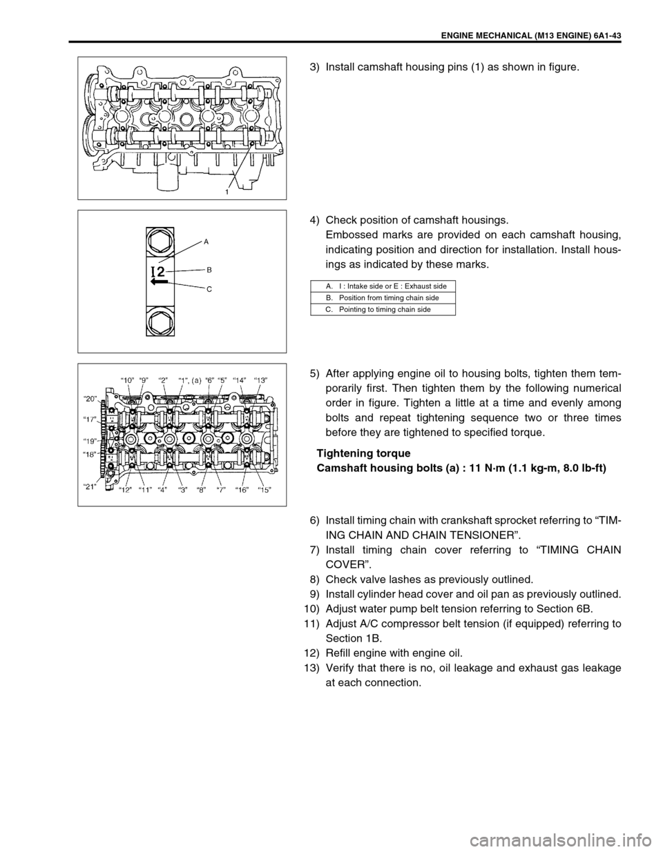
3) Install camshaft housing pins (1) as shown in figure.
4) Check position of camshaft housings.
Embossed marks are provided on each camshaft housing,
indicating position and direction for installation. Install hous-
ings as indicated by these marks.
5) After applying engine oil to housing bolts, tighten them tem-
porarily first. Then tighten them by the following numerical
order in figure. Tighten a little at a time and evenly among
bolts and repeat tightening sequence two or three times
before they are tightened to specified torque.
Tightening torque
Camshaft housing bolts (a) : 11 N·m (1.1 kg-m, 8.0 lb-ft)
6) Install timing chain with crankshaft sprocket referring to “TIM-
ING CHAIN AND CHAIN TENSIONER”.
7) Install timing chain cover referring to “TIMING CHAIN
COVER”.
8) Check valve lashes as previously outlined.
9) Install cylinder head cover and oil pan as previously outlined.
10) Adjust water pump belt tension referring to Section 6B.
11) Adjust A/C compressor belt tension (if equipped) referring to
Section 1B.
12) Refill engine with engine oil.
13) Verify that there is no, oil leakage and exhaust gas leakage
at each connection.
A. I : Intake side or E : Exhaust side
B. Position from timing chain side
C. Pointing to timing chain side
Page 545 of 698
6A1-44 ENGINE MECHANICAL (M13 ENGINE)
VALVES AND CYLINDER HEAD
REMOVAL
1) Relieve fuel pressure according to procedure described in
Section 6.
2) Disconnect negative cable at battery.
3) Drain engine oil.
[A]✱1) Tighten all bolts at 40 N·m (4.0 kg-m)
2) Turn all bolts at 60°
3) Then, Turn all bolt at 60° once again6. Intake valve 12. Knock pin
1. Valve cotters 7. Exhaust valve
Tightening torque
2. Valve spring retainer 8. Valve guide
Do not reuse.
3. Valve spring 9. Cylinder head bolt
: Never reuse it due to plastic deformation
tightening bolt.Apply engine oil to sliding surface of
each part.
4. Valve stem seal 10. Cylinder head
5. Valve spring seat 11. Cylinder head gasket
: “TOP” mark provided on gasket comes to
crankshaft pulley side, facing up.
Page 546 of 698

ENGINE MECHANICAL (M13 ENGINE) 6A1-45
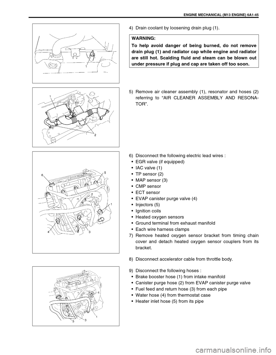
4) Drain coolant by loosening drain plug (1).
5) Remove air cleaner assembly (1), resonator and hoses (2)
referring to “AIR CLEANER ASSEMBLY AND RESONA-
TOR”.
6) Disconnect the following electric lead wires :
EGR valve (if equipped)
IAC valve (1)
TP sensor (2)
MAP sensor (3)
CMP sensor
ECT sensor
EVAP canister purge valve (4)
Injectors (5)
Ignition coils
Heated oxygen sensors
Ground terminal from exhaust manifold
Each wire harness clamps
7) Remove heated oxygen sensor bracket from timing chain
cover and detach heated oxygen sensor couplers from its
bracket.
8) Disconnect accelerator cable from throttle body.
9) Disconnect the following hoses :
Brake booster hose (1) from intake manifold
Canister purge hose (2) from EVAP canister purge valve
Fuel feed and return hose (3) from each pipe
Water hose (4) from thermostat case
Heater inlet hose (5) from its pipe WARNING:
To help avoid danger of being burned, do not remove
drain plug (1) and radiator cap while engine and radiator
are still hot. Scalding fluid and steam can be blown out
under pressure if plug and cap are taken off too soon.
Page 547 of 698

6A1-46 ENGINE MECHANICAL (M13 ENGINE)
10) Remove intake manifold stiffener (1).
11) Remove oil pan referring to “OIL PAN AND OIL PUMP
STRAINER”.
12) Remove cylinder head cover referring to “CYLINDER HEAD
COVER”.
13) Remove timing chain cover referring to “TIMING CHAIN
COVER”.
14) Remove timing chain referring to “TIMING CHAIN AND
CHAIN TENSIONER”.
15) Remove intake and exhaust camshafts referring to “CAM-
SHAFT, TAPPET AND SHIM”.
16) Loosen cylinder head bolts in such order as indicated in fig-
ure by using a 12 corner socket wrenches and remove them.
17) Check all around cylinder head for any other parts required
to be removed or disconnected and remove or disconnect
whatever necessary.
18) Remove exhaust manifold, if necessary, referring to
“EXHAUST MANIFOLD”.
19) Remove cylinder head with intake manifold and exhaust
manifold. Use lifting device, if necessary.
NOTE:
Don’t forget to remove bolt (M8) (1) as shown in figure.
Never reuse cylinder head bolts once disassembled it
due to plastic deformation tightening. Be sure to use
new cylinder head bolts when installing.