Page 237 of 698

3E-24 REAR SUSPENSION
2) Press in a new bearing (2) and retainer ring (3) in order by
using an hydraulic press (4).
3) Install wheel sensor ring (if equipped with ABS).
Refer to “REAR WHEEL SENSOR RING” of Section 5E.
4) Inspect axle shaft length.
Rear axle shaft length “a”
Left side : 657.5 mm (25.9 in.)
Right side : 785.5 mm (30.9 in.)
5) Apply grease to axle shaft oil seal (1) lip as shown.
“A” : Grease 99000-25010
6) Apply sealant to mating surface of axle housing (2) with
brake back plate.
“B” : Sealant 99000-31090
7) Install rear axle shaft to rear axle housing and tighten brake
back plate bolts to specified torque.
Tightening torque
Brake back plate bolts (a) : 23 N·m (2.3 kg-m, 17.0 lb-ft) NOTE:
Install wheel bearing spacer (1) with the tapered side of
its inner diameter directed toward outside, or brake
drum side.
Install wheel bearing with its sealed side directed
toward brake drum side.
Use care not to cause any damage to outside of
retainer ring.
A : Tapered side
B : Sealed side
C : Differential side
D : Without ABS
E : With ABS
NOTE:
Make sure to remove old sealant before applying it anew.
NOTE:
When installing rear axle shaft, be careful not to cause
damage to oil seal lip in axle housing.
Page 278 of 698

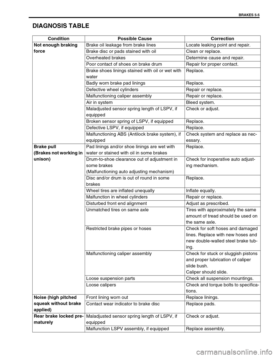
BRAKES 5-5
DIAGNOSIS TABLE
Condition Possible Cause Correction
Not enough braking
forceBrake oil leakage from brake lines Locate leaking point and repair.
Brake disc or pads stained with oil Clean or replace.
Overheated brakes Determine cause and repair.
Poor contact of shoes on brake drum Repair for proper contact.
Brake shoes linings stained with oil or wet with
waterReplace.
Badly worn brake pad linings Replace.
Defective wheel cylinders Repair or replace.
Malfunctioning caliper assembly Repair or replace.
Air in system Bleed system.
Maladjusted sensor spring length of LSPV, if
equippedCheck or adjust.
Broken sensor spring of LSPV, if equipped Replace.
Defective LSPV, if equipped Replace.
Malfunctioning ABS (Antilock brake system), if
equippedCheck system and replace as nec-
essary.
Brake pull
(Brakes not working in
unison)Pad linings and/or shoe linings are wet with
water or stained with oil in some brakesReplace.
Drum-to-shoe clearance out of adjustment in
some brakes
(Malfunctioning auto adjusting mechanism)Check for inoperative auto adjust-
ing mechanism.
Disc and/or drum is out of round in some
brakesReplace.
Wheel tires are inflated unequally Inflate equally.
Malfunction in wheel cylinders Repair or replace.
Disturbed front end alignment Adjust as prescribed.
Unmatched tires on same axle Tires with approximately the same
amount of tread should be used on
the same axle.
Restricted brake pipes or hoses Check for soft hoses and damaged
lines. Replace with new hoses and
new double-walled steel brake tub-
ing.
Malfunctioning caliper assembly Check for stuck or sluggish pistons
and proper lubrication of caliper
slide bush.
Caliper should slide.
Loose suspension parts Check all suspension mountings.
Loose calipers Check and torque bolts to specifica-
tions.
Noise (high pitched
squeak without brake
applied)Front lining worn out Replace linings.
Contact wear indicator to brake disc Replace pads.
Rear brake locked pre-
maturelyMaladjusted sensor spring length of LSPV, if
equippedCheck or adjust.
Malfunction LSPV assembly, if equipped Replace assembly.
Page 282 of 698

BRAKES 5-9
EXCESSIVE PEDAL TRAVEL INSPECTION
1) Start engine.
2) Depress brake pedal a few times.
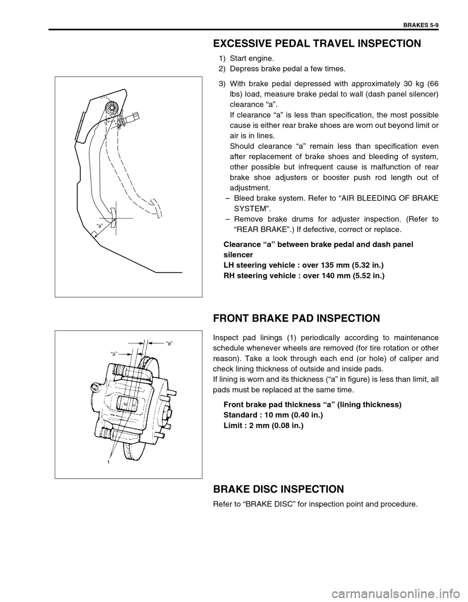
3) With brake pedal depressed with approximately 30 kg (66
lbs) load, measure brake pedal to wall (dash panel silencer)
clearance “a”.
If clearance “a” is less than specification, the most possible
cause is either rear brake shoes are worn out beyond limit or
air is in lines.
Should clearance “a” remain less than specification even
after replacement of brake shoes and bleeding of system,
other possible but infrequent cause is malfunction of rear
brake shoe adjusters or booster push rod length out of
adjustment.
–Bleed brake system. Refer to “AIR BLEEDING OF BRAKE
SYSTEM”.
–Remove brake drums for adjuster inspection. (Refer to
“REAR BRAKE”.) If defective, correct or replace.
Clearance “a” between brake pedal and dash panel
silencer
LH steering vehicle : over 135 mm (5.32 in.)
RH steering vehicle : over 140 mm (5.52 in.)
FRONT BRAKE PAD INSPECTION
Inspect pad linings (1) periodically according to maintenance
schedule whenever wheels are removed (for tire rotation or other
reason). Take a look through each end (or hole) of caliper and
check lining thickness of outside and inside pads.
If lining is worn and its thickness (“a” in figure) is less than limit, all
pads must be replaced at the same time.
Front brake pad thickness “a” (lining thickness)
Standard : 10 mm (0.40 in.)
Limit : 2 mm (0.08 in.)
BRAKE DISC INSPECTION
Refer to “BRAKE DISC” for inspection point and procedure.
“a”
Page 310 of 698
BRAKES 5-37
7) Install cup (1) and washer (2) such a direction as shown.
8) Remove cap cup (1) from cap with caring not to cause any
damage to inside of cap (2).
9) Install cap cup and O-rings (3) to cap such a direction as
shown.
10) Install cap and tighten it to specified torque, then confirm the
length “A”.
Tightening torque
Cap (a) : 14 N·m (1.4 kg-m, 10.5 lb-ft)
Cap installation position
“A” : Less than 26 mm (1.02 in.)
INSPECTION AFTER ASSEMBLY
1) Install radiator cap test with special tool to master cylinder
port (1).
Special tool
(A) : 09952-46010
(B) : 09952-26020
2) Apply air and confirm that pressure is not applied.NOTE:
Primary cup is the same as secondary cup.
Primary cup is the largest compared with that of cap
and sleeve.
NOTE:
For without ABS vehicle, install special tool (B) to oppo-
site side port (2).
1(B)
2 (A)
Page 312 of 698

BRAKES 5-39
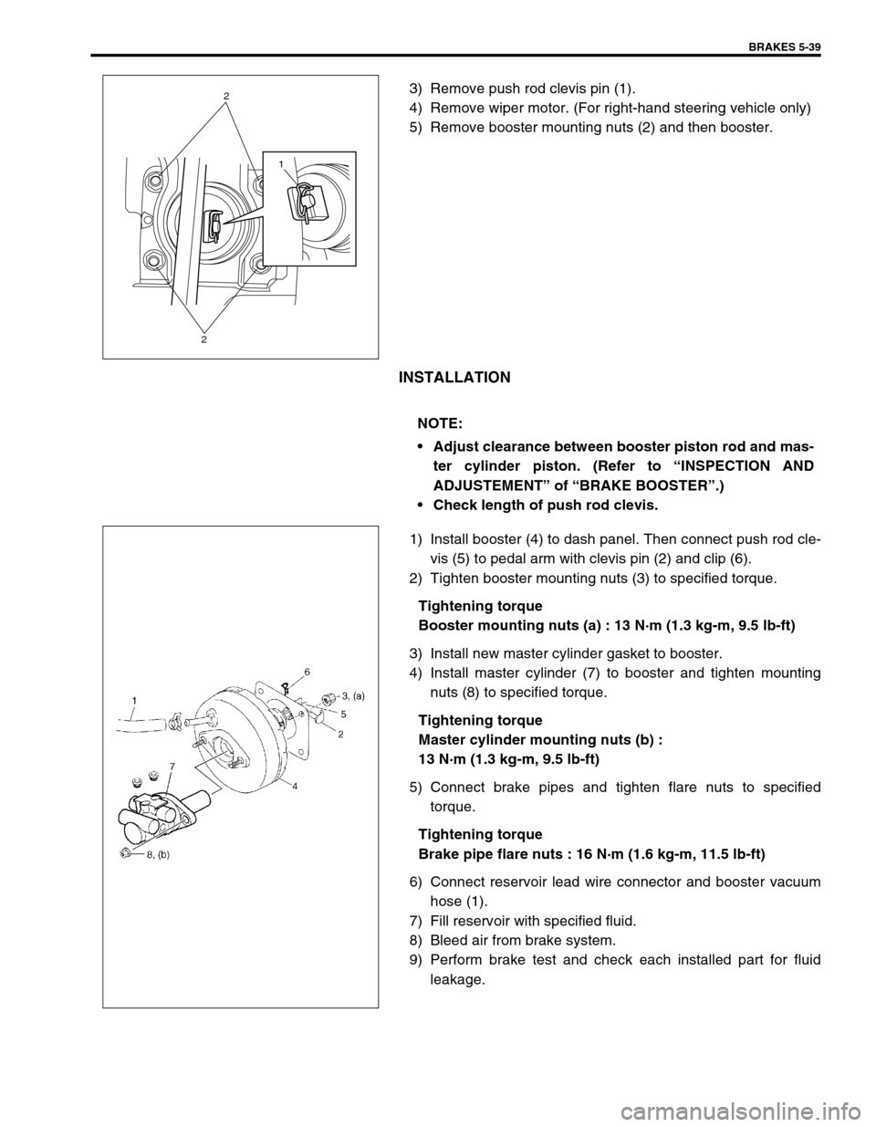
3) Remove push rod clevis pin (1).
4) Remove wiper motor. (For right-hand steering vehicle only)
5) Remove booster mounting nuts (2) and then booster.
INSTALLATION
1) Install booster (4) to dash panel. Then connect push rod cle-
vis (5) to pedal arm with clevis pin (2) and clip (6).
2) Tighten booster mounting nuts (3) to specified torque.
Tightening torque
Booster mounting nuts (a) : 13 N·m (1.3 kg-m, 9.5 lb-ft)
3) Install new master cylinder gasket to booster.
4) Install master cylinder (7) to booster and tighten mounting
nuts (8) to specified torque.
Tightening torque
Master cylinder mounting nuts (b) :
13 N·m (1.3 kg-m, 9.5 lb-ft)
5) Connect brake pipes and tighten flare nuts to specified
torque.
Tightening torque
Brake pipe flare nuts : 16 N·m (1.6 kg-m, 11.5 lb-ft)
6) Connect reservoir lead wire connector and booster vacuum
hose (1).
7) Fill reservoir with specified fluid.
8) Bleed air from brake system.
9) Perform brake test and check each installed part for fluid
leakage.
1
2
2
NOTE:
Adjust clearance between booster piston rod and mas-
ter cylinder piston. (Refer to “INSPECTION AND
ADJUSTEMENT” of “BRAKE BOOSTER”.)
Check length of push rod clevis.
Page 313 of 698

5-40 BRAKES
INSPECTION AND ADJUSTMENT
Installation Position Of Push Rod
If push rod clevis (1) has been removed, adjust distance between
booster installation surface (without including packing) and the
center of clevis pin hole to standard value “a” and tighten nut (2)
to specified torque.
Distance “a” between center of booster clevis pin hole
and booster surface
Standard : 97 - 98 mm (3.82 - 3.86 in.)
Tightening torque
Clevis pin lock nut (a) : 19 N·m (1.9 kg-m, 14.0 lb-ft)
Clearance Between Booster Piston Rod And Master Cylin-
der Piston
The length of booster piston rod (1) is adjusted to provide speci-
fied clearance “a” between piston rod (1) end and master cylinder
piston (2).
Before measuring clearance, push piston rod several times
so as to make sure reaction disc is in place.
Keep inside of booster at atmospheric pressure for measure-
ment.
Measure length “a” of piston rod, i.e. distance between piston rod
and mating surface of booster-to-master cylinder.
Length “a” of piston rod
: 30.3 - 30.5 mm (1.193 - 1.200 in.)
If measurement is out of specification, adjust piston rod by turning
adjusting screw of piston rod.
Special tool
(B) : 09952-16020
NOTE:
Remove gasket from booster, if equipped.
Page 322 of 698

BRAKES 5-49
INSTALLATION
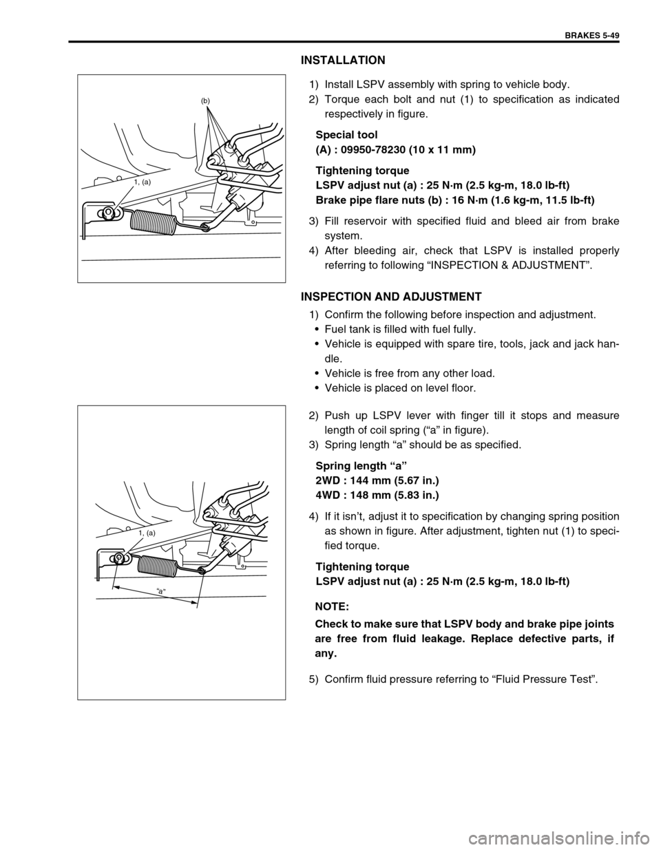
1) Install LSPV assembly with spring to vehicle body.
2) Torque each bolt and nut (1) to specification as indicated
respectively in figure.
Special tool
(A) : 09950-78230 (10 x 11 mm)
Tightening torque
LSPV adjust nut (a) : 25 N·m (2.5 kg-m, 18.0 lb-ft)
Brake pipe flare nuts (b) : 16 N·m (1.6 kg-m, 11.5 lb-ft)
3) Fill reservoir with specified fluid and bleed air from brake
system.
4) After bleeding air, check that LSPV is installed properly
referring to following “INSPECTION & ADJUSTMENT”.
INSPECTION AND ADJUSTMENT
1) Confirm the following before inspection and adjustment.
Fuel tank is filled with fuel fully.
Vehicle is equipped with spare tire, tools, jack and jack han-
dle.
Vehicle is free from any other load.
Vehicle is placed on level floor.
2) Push up LSPV lever with finger till it stops and measure
length of coil spring (“a” in figure).
3) Spring length “a” should be as specified.
Spring length “a”
2WD : 144 mm (5.67 in.)
4WD : 148 mm (5.83 in.)
4) If it isn’t, adjust it to specification by changing spring position
as shown in figure. After adjustment, tighten nut (1) to speci-
fied torque.
Tightening torque
LSPV adjust nut (a) : 25 N·m (2.5 kg-m, 18.0 lb-ft)
5) Confirm fluid pressure referring to “Fluid Pressure Test”.
1, (a)
(b)
NOTE:
Check to make sure that LSPV body and brake pipe joints
are free from fluid leakage. Replace defective parts, if
any.
1, (a)
“a”
Page 549 of 698

6A1-48 ENGINE MECHANICAL (M13 ENGINE)
INSPECTION
Valve Guides
Using a micrometer and bore gauge, take diameter readings on
valve stems and guides to check stem-to-guide clearance. Be
sure to take reading at more than one place along the length of
each stem and guide.
If clearance exceeds limit, replace valve and valve guide.
Valve stem-to-guide clearance
Valve stem diameter [A]
Valve guide bore [B] standard
In and Ex : 6.000 – 6.012 mm (0.2362 – 0.2367 in.) for 69G
type valve
In and Ex : 5.485 – 5.510 mm (0.2159 – 0.2169 in.) for 54G
type valve
If bore gauge is not available, check end deflection of valve stem
with a dial gauge instead.
Move stem end in directions (1) and (2) to measure end deflec-
tion.
If deflection exceeds its limit, replace valve stem and valve guide.
Valve stem end deflection limit
In : 0.14 mm (0.005 in.)
Ex : 0.18 mm (0.007 in.)Valve type Standard Limit
69GIn0.020 – 0.047 mm
(0.0008 – 0.0019 in.)0.07 mm
(0.0028 in.)
Ex0.045 – 0.072 mm
(0.0018 – 0.0028 in.)0.09 mm
(0.0035 in.)
54GIn0.020 – 0.030 mm
(0.0008 – 0.0012 in.)0.05 mm
(0.0017 in.)
Ex0.045 – 0.055 mm
(0.0018 – 0.0022 in.)0.07 mm
(0.0028 in.)
Valve type Standard
69GIn5.965 – 5.980 mm
(0.2348 – 0.2354 in.)
Ex5.940 – 5.955 mm
(0.2339 – 0.2344 in.)
54GIn5.465 – 5.480 mm
(0.2152 – 0.2157 in.)
Ex5.440 – 5.455 mm
(0.2142 – 0.2148 in.)
1. Emboss mark 54G or 69G