Page 553 of 698

6A1-52 ENGINE MECHANICAL (M13 ENGINE)
Valve Springs
Referring to data given below, check to be sure that each
spring is in sound condition, free of any evidence of break-
age or weakening. Remember, weakened valve springs can
cause chatter, not to mention possibility of reducing power
output due to gas leakage caused by decreased seating
pressure.
Valve spring free length for engine equipped with 69G
type valve
Standard : 43.00 mm (1.693 in.)
Limit : 42.00 mm (1.652 in.)
Valve spring free length for engine equipped with 54G
type valve
Standard : 36.83 mm (1.450 in.)
Limit : 35.83 mm (1.410 in.)
Valve spring preload for engine equipped with 69G type
valve
Standard : 110 – 126 N (11.2 – 12.8 kg) for 39.50 mm
(24.7 – 28.2 lb/1.555 in.)
Limit : 105 N (10.7 kg) for 39.5 mm (23.6 lb/1.555 in.)
Valve spring preload for engine equipped with 54G type
valve
Standard : 107 – 125 N (10.7 – 12.5 kg) for 31.50 mm
(23.6 – 27.6 lb/1.240 in.)
Limit : 102 N (10.4 kg) for 31.50 mm (22.9 lb/1.240 in.)
Spring skewness:
Use a square and surface plate to check each spring for
skewness in terms of clearance between end of valve spring
and square. Valve springs found to exhibit a larger clearance
than limit given below must be replaced.
Valve spring skewness
Limit : 2.0 mm (0.079 in.) for engine equipped with 69G
type valve
Limit : 1.6 mm (0.063 in.) for engine equipped with 54G
type valve
1. Valve
2. Emboss mark 54G or 69G
1. Valve
2. Emboss mark 54G or 69G
Page 577 of 698

6A1-76 ENGINE MECHANICAL (M13 ENGINE)
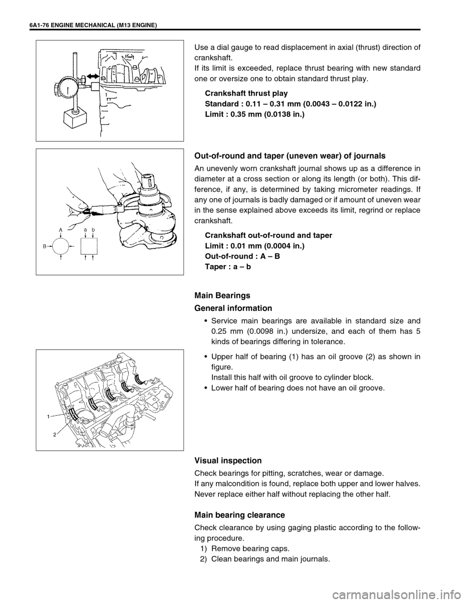
Use a dial gauge to read displacement in axial (thrust) direction of
crankshaft.
If its limit is exceeded, replace thrust bearing with new standard
one or oversize one to obtain standard thrust play.
Crankshaft thrust play
Standard : 0.11 – 0.31 mm (0.0043 – 0.0122 in.)
Limit : 0.35 mm (0.0138 in.)
Out-of-round and taper (uneven wear) of journals
An unevenly worn crankshaft journal shows up as a difference in
diameter at a cross section or along its length (or both). This dif-
ference, if any, is determined by taking micrometer readings. If
any one of journals is badly damaged or if amount of uneven wear
in the sense explained above exceeds its limit, regrind or replace
crankshaft.
Crankshaft out-of-round and taper
Limit : 0.01 mm (0.0004 in.)
Out-of-round : A – B
Taper : a – b
Main Bearings
General information
Service main bearings are available in standard size and
0.25 mm (0.0098 in.) undersize, and each of them has 5
kinds of bearings differing in tolerance.
Upper half of bearing (1) has an oil groove (2) as shown in
figure.
Install this half with oil groove to cylinder block.
Lower half of bearing does not have an oil groove.
Visual inspection
Check bearings for pitting, scratches, wear or damage.
If any malcondition is found, replace both upper and lower halves.
Never replace either half without replacing the other half.
Main bearing clearance
Check clearance by using gaging plastic according to the follow-
ing procedure.
1) Remove bearing caps.
2) Clean bearings and main journals.
Page 680 of 698

6G-8 CRANKING SYSTEM
SPECIFICATION
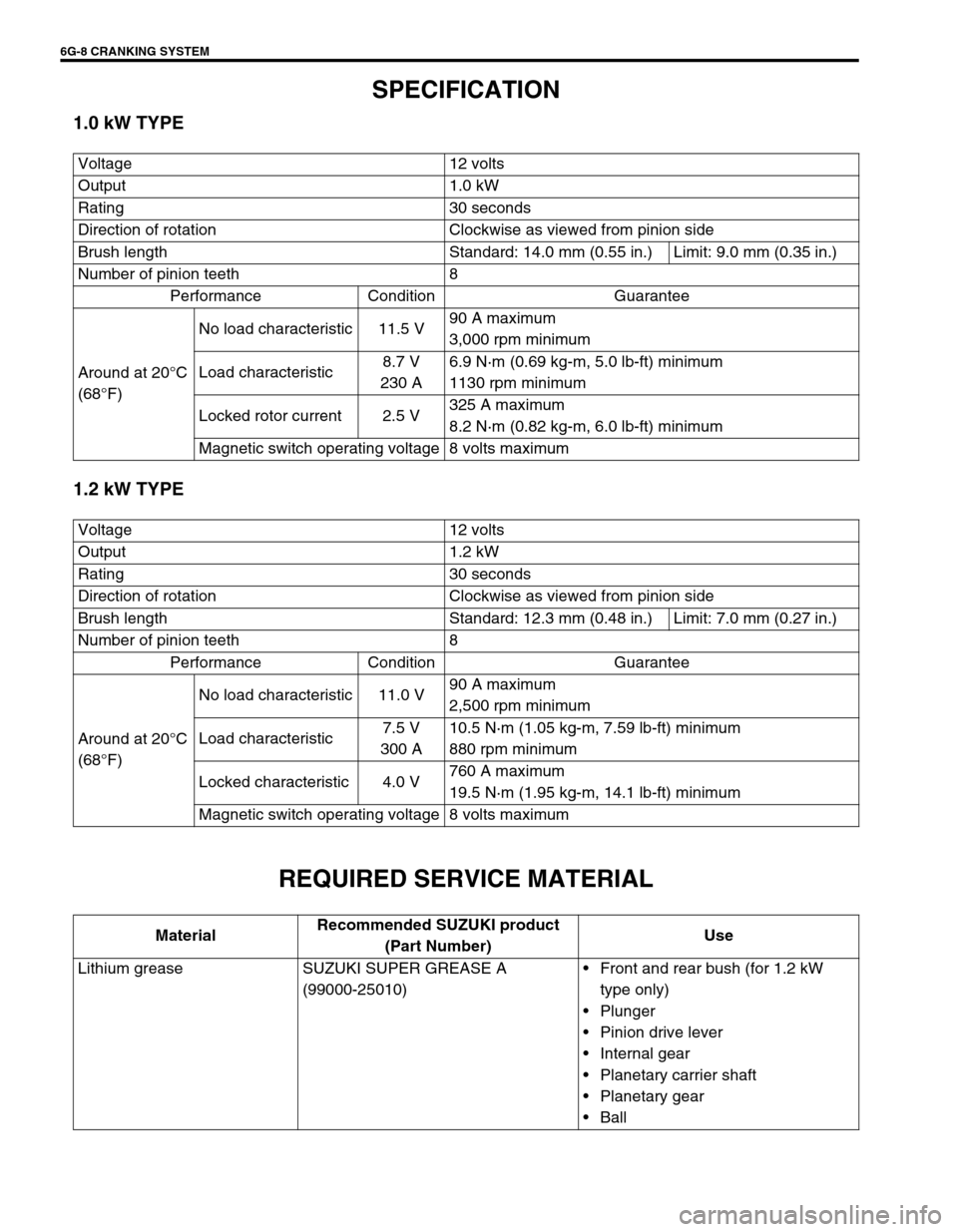
1.0 kW TYPE
1.2 kW TYPE
REQUIRED SERVICE MATERIAL
Voltage 12 volts
Output 1.0 kW
Rating 30 seconds
Direction of rotation Clockwise as viewed from pinion side
Brush length Standard: 14.0 mm (0.55 in.) Limit: 9.0 mm (0.35 in.)
Number of pinion teeth 8
Performance Condition Guarantee
Around at 20°C
(68°F)No load characteristic 11.5 V90 A maximum
3,000 rpm minimum
Load characteristic8.7 V
230 A6.9 N·m (0.69 kg-m, 5.0 lb-ft) minimum
1130 rpm minimum
Locked rotor current 2.5 V325 A maximum
8.2 N·m (0.82 kg-m, 6.0 lb-ft) minimum
Magnetic switch operating voltage 8 volts maximum
Voltage 12 volts
Output 1.2 kW
Rating 30 seconds
Direction of rotation Clockwise as viewed from pinion side
Brush length Standard: 12.3 mm (0.48 in.) Limit: 7.0 mm (0.27 in.)
Number of pinion teeth 8
Performance Condition Guarantee
Around at 20°C
(68°F)No load characteristic 11.0 V90 A maximum
2,500 rpm minimum
Load characteristic7.5 V
300 A10.5 N·m (1.05 kg-m, 7.59 lb-ft) minimum
880 rpm minimum
Locked characteristic 4.0 V760 A maximum
19.5 N·m (1.95 kg-m, 14.1 lb-ft) minimum
Magnetic switch operating voltage 8 volts maximum
MaterialRecommended SUZUKI product
(Part Number)Use
Lithium grease SUZUKI SUPER GREASE A
(99000-25010)Front and rear bush (for 1.2 kW
type only)
Plunger
Pinion drive lever
Internal gear
Planetary carrier shaft
Planetary gear
Ball
Page 693 of 698

CHARGING SYSTEM 6H-13
2) Using ohmmeter, check that there is no continuity between
coil leads and stator core. If there is continuity, replace sta-
tor.
BRUSH AND BRUSH HOLDER
Check each brush for wear by measuring its length as shown. If
brush is found worn down to service limit, replace brush.
Exposed brush length “a”
Standard: 10.5 mm (0.41 in.)
Limit: 1.5 mm (0.06 in.)
RECTIFIER
1) Using an ohmmeter, connect one tester probe to the “B” ter-
minal (1) and the other to each rectifier terminal (2).
2) Reverse the polarity of the tester probes and repeat step 1).
3) Check that one shows continuity and the other shows no
continuity.
If there is continuity, replace the rectifier.
4) Using an ohmmeter, connect one tester probe to each nega-
tive terminal (1) and the other to each rectifier terminal (2).
5) Reverse the polarity of the tester probes and repeat step 4).
6) Check that one shows continuity and the other shows no
continuity.
If there is continuity, replace the rectifier.
Page 694 of 698

6H-14 CHARGING SYSTEM
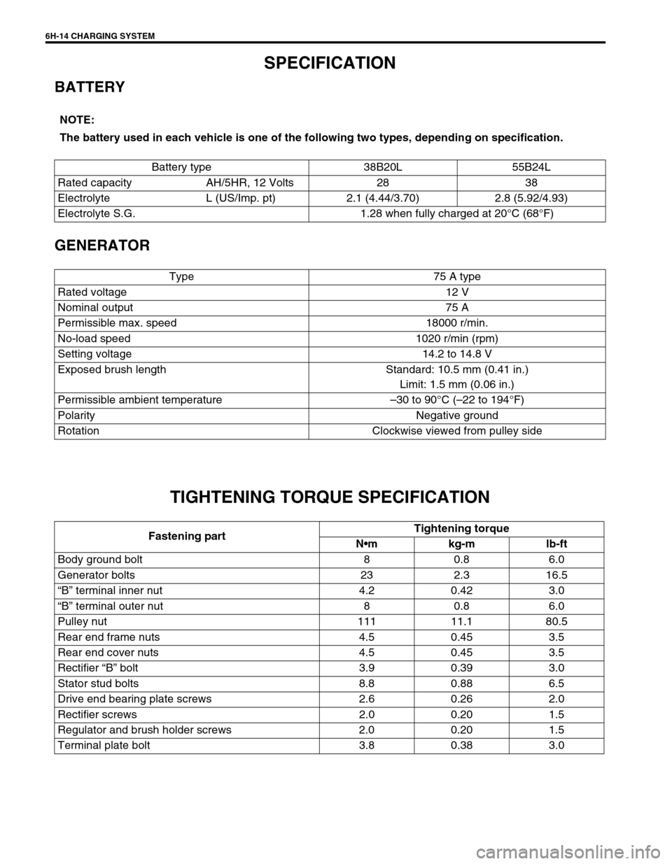
SPECIFICATION
BATTERY
GENERATOR
TIGHTENING TORQUE SPECIFICATION
NOTE:
The battery used in each vehicle is one of the following two types, depending on specification.
Battery type 38B20L 55B24L
Rated capacity AH/5HR, 12 Volts 28 38
Electrolyte L (US/Imp. pt) 2.1 (4.44/3.70) 2.8 (5.92/4.93)
Electrolyte S.G. 1.28 when fully charged at 20°C (68°F)
Type 75 A type
Rated voltage 12 V
Nominal output 75 A
Permissible max. speed 18000 r/min.
No-load speed 1020 r/min (rpm)
Setting voltage 14.2 to 14.8 V
Exposed brush length Standard: 10.5 mm (0.41 in.)
Limit: 1.5 mm (0.06 in.)
Permissible ambient temperature–30 to 90°C (–22 to 194°F)
Polarity Negative ground
Rotation Clockwise viewed from pulley side
Fastening partTightening torque
Nm kg-m lb-ft
Body ground bolt 8 0.8 6.0
Generator bolts 23 2.3 16.5
“B” terminal inner nut 4.2 0.42 3.0
“B” terminal outer nut 8 0.8 6.0
Pulley nut 111 11.1 80.5
Rear end frame nuts 4.5 0.45 3.5
Rear end cover nuts 4.5 0.45 3.5
Rectifier “B” bolt 3.9 0.39 3.0
Stator stud bolts 8.8 0.88 6.5
Drive end bearing plate screws 2.6 0.26 2.0
Rectifier screws 2.0 0.20 1.5
Regulator and brush holder screws 2.0 0.20 1.5
Terminal plate bolt 3.8 0.38 3.0
Page:
< prev 1-8 9-16 17-24