Page 279 of 698

5-6 BRAKES
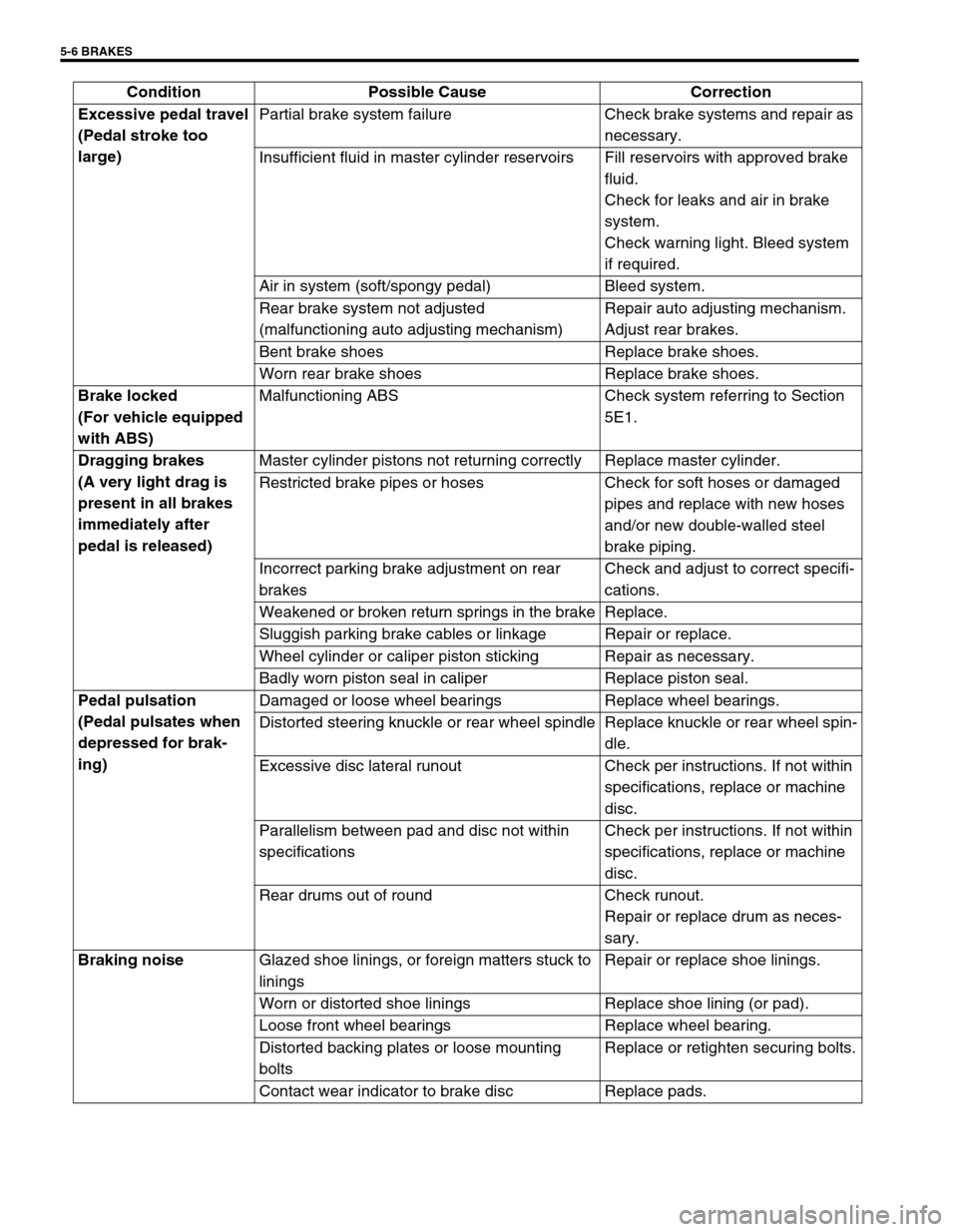
Excessive pedal travel
(Pedal stroke too
large)Partial brake system failure Check brake systems and repair as
necessary.
Insufficient fluid in master cylinder reservoirs Fill reservoirs with approved brake
fluid.
Check for leaks and air in brake
system.
Check warning light. Bleed system
if required.
Air in system (soft/spongy pedal) Bleed system.
Rear brake system not adjusted
(malfunctioning auto adjusting mechanism)Repair auto adjusting mechanism.
Adjust rear brakes.
Bent brake shoes Replace brake shoes.
Worn rear brake shoes Replace brake shoes.
Brake locked
(For vehicle equipped
with ABS)Malfunctioning ABS Check system referring to Section
5E1.
Dragging brakes
(A very light drag is
present in all brakes
immediately after
pedal is released)Master cylinder pistons not returning correctly Replace master cylinder.
Restricted brake pipes or hoses Check for soft hoses or damaged
pipes and replace with new hoses
and/or new double-walled steel
brake piping.
Incorrect parking brake adjustment on rear
brakesCheck and adjust to correct specifi-
cations.
Weakened or broken return springs in the brake Replace.
Sluggish parking brake cables or linkage Repair or replace.
Wheel cylinder or caliper piston sticking Repair as necessary.
Badly worn piston seal in caliper Replace piston seal.
Pedal pulsation
(Pedal pulsates when
depressed for brak-
ing)Damaged or loose wheel bearings Replace wheel bearings.
Distorted steering knuckle or rear wheel spindle Replace knuckle or rear wheel spin-
dle.
Excessive disc lateral runout Check per instructions. If not within
specifications, replace or machine
disc.
Parallelism between pad and disc not within
specificationsCheck per instructions. If not within
specifications, replace or machine
disc.
Rear drums out of round Check runout.
Repair or replace drum as neces-
sary.
Braking noise
Glazed shoe linings, or foreign matters stuck to
liningsRepair or replace shoe linings.
Worn or distorted shoe linings Replace shoe lining (or pad).
Loose front wheel bearings Replace wheel bearing.
Distorted backing plates or loose mounting
boltsReplace or retighten securing bolts.
Contact wear indicator to brake disc Replace pads. Condition Possible Cause Correction
Page 282 of 698

BRAKES 5-9
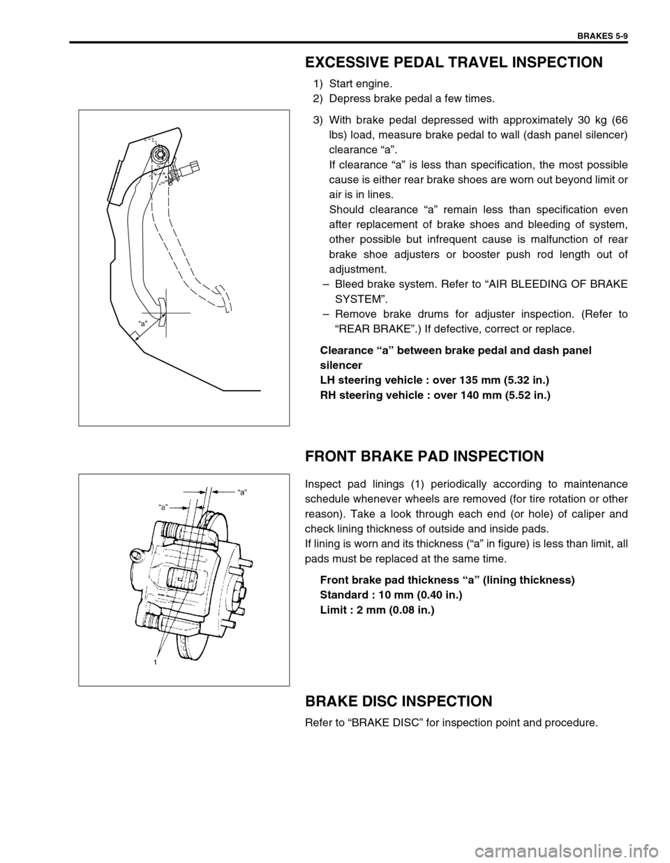
EXCESSIVE PEDAL TRAVEL INSPECTION
1) Start engine.
2) Depress brake pedal a few times.
3) With brake pedal depressed with approximately 30 kg (66
lbs) load, measure brake pedal to wall (dash panel silencer)
clearance “a”.
If clearance “a” is less than specification, the most possible
cause is either rear brake shoes are worn out beyond limit or
air is in lines.
Should clearance “a” remain less than specification even
after replacement of brake shoes and bleeding of system,
other possible but infrequent cause is malfunction of rear
brake shoe adjusters or booster push rod length out of
adjustment.
–Bleed brake system. Refer to “AIR BLEEDING OF BRAKE
SYSTEM”.
–Remove brake drums for adjuster inspection. (Refer to
“REAR BRAKE”.) If defective, correct or replace.
Clearance “a” between brake pedal and dash panel
silencer
LH steering vehicle : over 135 mm (5.32 in.)
RH steering vehicle : over 140 mm (5.52 in.)
FRONT BRAKE PAD INSPECTION
Inspect pad linings (1) periodically according to maintenance
schedule whenever wheels are removed (for tire rotation or other
reason). Take a look through each end (or hole) of caliper and
check lining thickness of outside and inside pads.
If lining is worn and its thickness (“a” in figure) is less than limit, all
pads must be replaced at the same time.
Front brake pad thickness “a” (lining thickness)
Standard : 10 mm (0.40 in.)
Limit : 2 mm (0.08 in.)
BRAKE DISC INSPECTION
Refer to “BRAKE DISC” for inspection point and procedure.
“a”
Page 283 of 698

5-10 BRAKES
PARKING BRAKE INSPECTION AND
ADJUSTMENT
INSPECTION
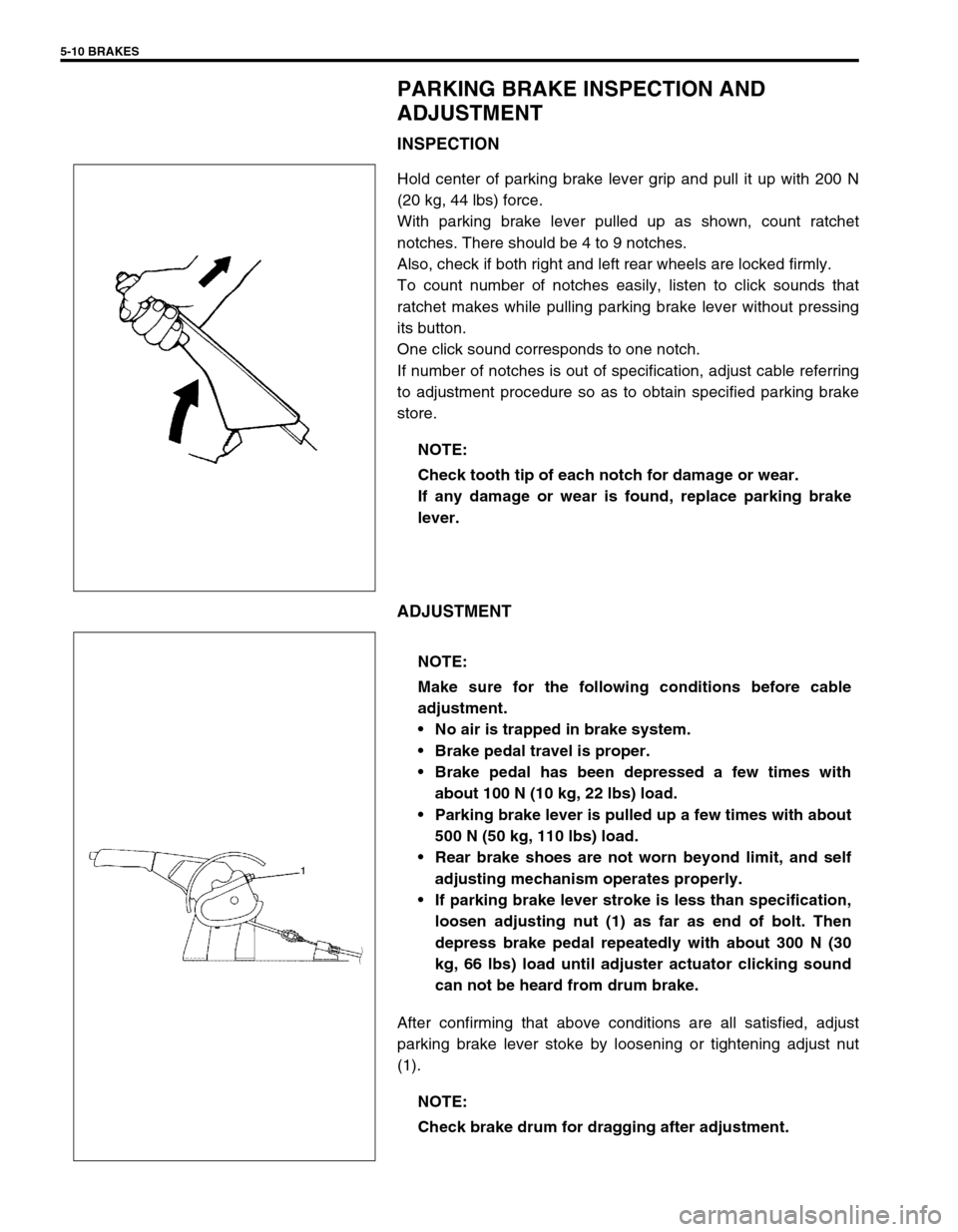
Hold center of parking brake lever grip and pull it up with 200 N
(20 kg, 44 lbs) force.
With parking brake lever pulled up as shown, count ratchet
notches. There should be 4 to 9 notches.
Also, check if both right and left rear wheels are locked firmly.
To count number of notches easily, listen to click sounds that
ratchet makes while pulling parking brake lever without pressing
its button.
One click sound corresponds to one notch.
If number of notches is out of specification, adjust cable referring
to adjustment procedure so as to obtain specified parking brake
store.
ADJUSTMENT
After confirming that above conditions are all satisfied, adjust
parking brake lever stoke by loosening or tightening adjust nut
(1).NOTE:
Check tooth tip of each notch for damage or wear.
If any damage or wear is found, replace parking brake
lever.
NOTE:
Make sure for the following conditions before cable
adjustment.
No air is trapped in brake system.
Brake pedal travel is proper.
Brake pedal has been depressed a few times with
about 100 N (10 kg, 22 lbs) load.
Parking brake lever is pulled up a few times with about
500 N (50 kg, 110 lbs) load.
Rear brake shoes are not worn beyond limit, and self
adjusting mechanism operates properly.
If parking brake lever stroke is less than specification,
loosen adjusting nut (1) as far as end of bolt. Then
depress brake pedal repeatedly with about 300 N (30
kg, 66 lbs) load until adjuster actuator clicking sound
can not be heard from drum brake.
NOTE:
Check brake drum for dragging after adjustment.
Page 286 of 698

BRAKES 5-13
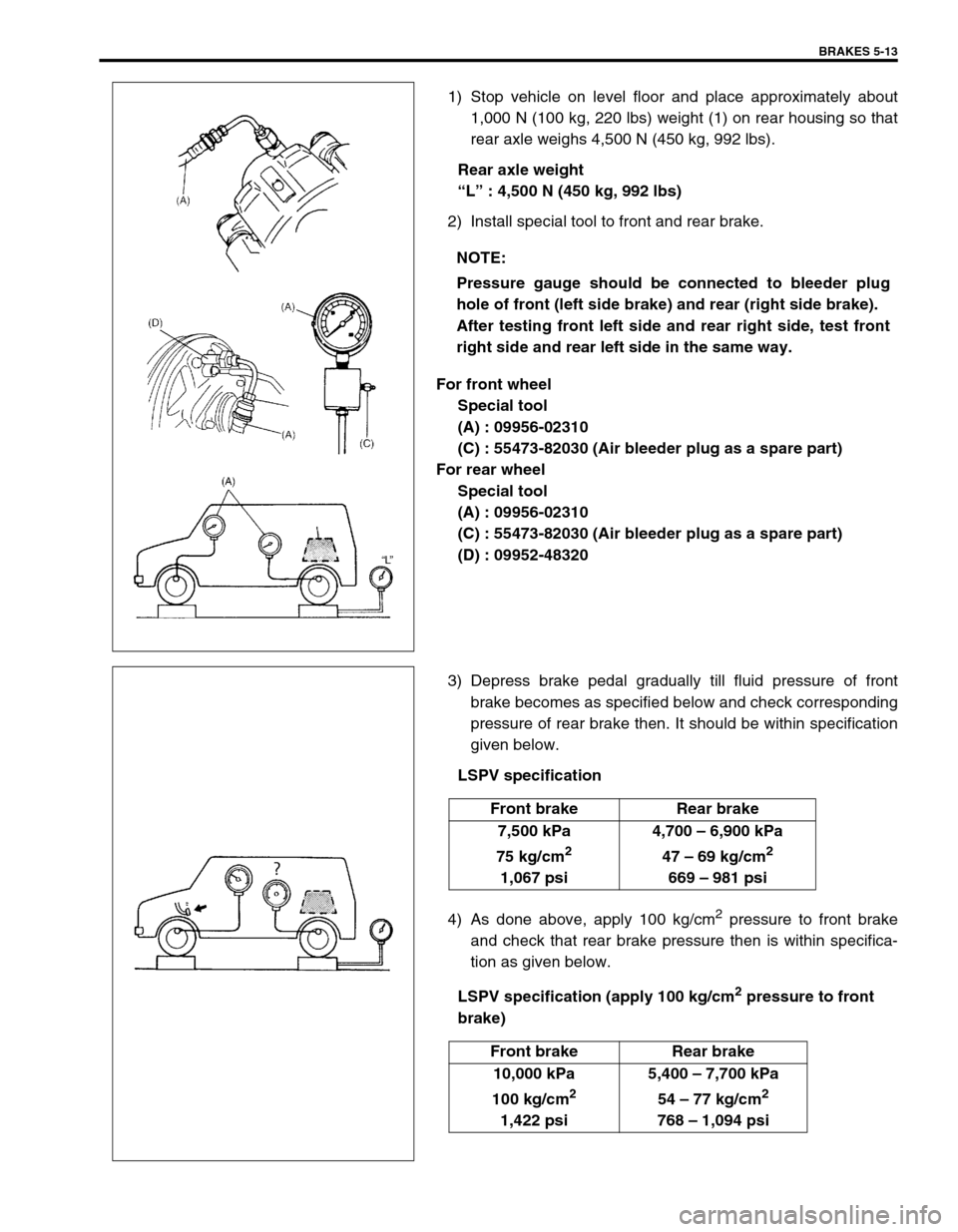
1) Stop vehicle on level floor and place approximately about
1,000 N (100 kg, 220 lbs) weight (1) on rear housing so that
rear axle weighs 4,500 N (450 kg, 992 lbs).
Rear axle weight
“L” : 4,500 N (450 kg, 992 lbs)
2) Install special tool to front and rear brake.
For front wheel
Special tool
(A) : 09956-02310
(C) : 55473-82030 (Air bleeder plug as a spare part)
For rear wheel
Special tool
(A) : 09956-02310
(C) : 55473-82030 (Air bleeder plug as a spare part)
(D) : 09952-48320
3) Depress brake pedal gradually till fluid pressure of front
brake becomes as specified below and check corresponding
pressure of rear brake then. It should be within specification
given below.
LSPV specification
4) As done above, apply 100 kg/cm
2 pressure to front brake
and check that rear brake pressure then is within specifica-
tion as given below.
LSPV specification (apply 100 kg/cm
2 pressure to front
brake) NOTE:
Pressure gauge should be connected to bleeder plug
hole of front (left side brake) and rear (right side brake).
After testing front left side and rear right side, test front
right side and rear left side in the same way.
Front brake Rear brake
7,500 kPa
75 kg/cm
2
1,067 psi4,700 – 6,900 kPa
47 – 69 kg/cm
2
669 – 981 psi
Front brake Rear brake
10,000 kPa
100 kg/cm
2
1,422 psi5,400 – 7,700 kPa
54 – 77 kg/cm
2
768 – 1,094 psi
Page 288 of 698

BRAKES 5-15
BRAKE HOSE AND PIPE INSPECTION
HOSE
The brake hose assembly should be checked for road hazard
damage, for cracks and chafing of outer cover, for leaks and blis-
ters. A light and mirror may be needed for an adequate inspec-
tion. If any of above conditions are observed on brake hose, it is
necessary to replace it.
PIPE
Inspect the pipe for damage, cracks, dents and corrosion. If any
defect is found, replace it.
ON-VEHICLE SERVICE
AIR BLEEDING OF BRAKE SYSTEM
Bleeding operation is necessary to remove air whenever it
entered hydraulic brake system.
Hydraulic lines of brake system are based on the diagonal split
system. When a brake pipe or hose was disconnected at the
wheel, bleeding operation must be performed at both ends of the
line of the removed pipe or hose. When any joint part of the mas-
ter cylinder of other joint part between the master cylinder and
each brake (wheel) was removed, the hydraulic brake system
must be bled at all 4 wheel brakes.
CAUTION:
Brake fluid is extremely damaging to paint. If fluid should
accidentally touch painted surface, immediately wipe
fluid from paint and clean painted surface.
NOTE:
Perform bleeding operation starting with wheel cylinder
farthest from master cylinder and then at front caliper of
the same brake line. Do the same on the other brake line.
1. Right brake caliper 4. Left wheel cylinder
2. Left brake caliper A : FRONT
3. Right wheel cylinder B : REAR
Page 290 of 698
BRAKES 5-17
FRONT BRAKE
BRAKE PAD
REMOVAL
1) Loosen wheel nuts and with vehicle lifted up, remove
wheels.
2) Remove caliper pin bolts (1).
1. Brake caliper carrier 9. Bleeder plug cap
2. Boot 10. Pad spring
3. Caliper 11. Anti noise shim
4. Disc brake piston 12. Caliper pin bolt
5. Piston seal
: Apply fluid (Brake, power steering or automatic transmission fluid).13. Brake disc
6. Cylinder boot
: Apply fluid (Brake, power steering or automatic transmission fluid).14. Slide pin
: Apply lithium grease (99000-25010).
7. Brake pad Tightening torque
8. Bleeder plugDo not reuse.
9
1
7
13
2
143
1226 N·m(2.6 kg-m)
85 N·m(8.5 kg-m)
8
8.5 N·m(0.85 kg-m)
10
5 4
6
11
Page 291 of 698

5-18 BRAKES
3) Remove caliper (1) from caliper carrier (2).
4) Remove brake pads (3).
INSPECTION
Check pad lining for wear. When wear exceeds limit, replace with
new one.
Brake pad thickness (lining thickness)
Standard : 10 mm (0.40 in.)
Limit : 1 mm (0.04 in.)
INSTALLATION
1) Set brake pad springs (1) and shim (2) and install brake
pads (3).
2) Install caliper and tighten caliper pin bolts (1) to specified
torque.
Tightening torque
Caliper pin bolts (a) : 26 N·m (2.6 kg-m, 19.0 lb-ft)
3) Tighten wheel temporarily and lower lift.NOTE:
Hang removed caliper (1) with a wire hook (4) or the like
so as to prevent brake hose from bending and twisting
excessively or being pulled.
Don’t operate brake pedal with brake pads removed.
CAUTION:
Never polish pad lining with sandpaper. If lining is pol-
ished with sandpaper, hard particles of sandpaper will be
deposited in lining and may damage disc. When pad lin-
ing requires correction, replace it with a new one.
NOTE:
When pads are removed, visually inspect caliper for
brake fluid leak. Correct leaky point, if any.
NOTE:
For right side brake, install pad with wear indicator (4) to
vehicle center side.
3
4
2
3
1
Page 292 of 698
BRAKES 5-19
4) Tighten wheel nuts to specified torque.
Tightening torque
Wheel nuts (a) : 85 N·m (8.5 kg-m, 61.5 lb-ft)
5) After completion of installation, check for brake effective-
ness.
CALIPER ASSEMBLY
REMOVAL
1) Hoist vehicle and remove wheel.
2) Remove E-ring (1).
3) Loosen flexible hose joint bolt (1) a little at caliper.
4) Remove caliper pin bolts (1).
5) Remove caliper from caliper carrier.
6) Disconnect flexible hose from caliper using care not to twist
it. As this will allow brake fluid to flow out of flexible hose,
have a container ready beforehand.
CAUTION:
Be careful not to twist flexible hose while loosening the
bolt.