Page 511 of 698

6A1-10 ENGINE MECHANICAL (M13 ENGINE)
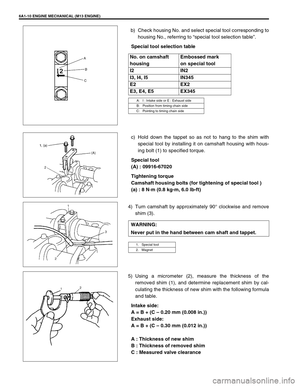
b) Check housing No. and select special tool corresponding to
housing No., referring to “special tool selection table”.
Special tool selection table
c) Hold down the tappet so as not to hang to the shim with
special tool by installing it on camshaft housing with hous-
ing bolt (1) to specified torque.
Special tool
(A) : 09916-67020
Tightening torque
Camshaft housing bolts (for tightening of special tool )
(a) : 8 N·m (0.8 kg-m, 6.0 lb-ft)
4) Turn camshaft by approximately 90° clockwise and remove
shim (3).
5) Using a micrometer (2), measure the thickness of the
removed shim (1), and determine replacement shim by cal-
culating the thickness of new shim with the following formula
and table.
Intake side:
A = B + (C – 0.20 mm (0.008 in.))
Exhaust side:
A = B + (C – 0.30 mm (0.012 in.))
A : Thickness of new shim
B : Thickness of removed shim
C : Measured valve clearance No. on camshaft
housingEmbossed mark
on special tool
I2 IN2
I3, I4, I5 IN345
E2 EX2
E3, E4, E5 EX345
A: I : Intake side or E : Exhaust side
B: Position from timing chain side
C: Pointing to timing chain side
WARNING:
Never put in the hand between cam shaft and tappet.
1. Special tool
2. Magnet
Page 512 of 698

ENGINE MECHANICAL (M13 ENGINE) 6A1-11
For example of intake side :
When thickness of removed shim is 2.40 mm (0.095 in.), and
measured valve clearance is 0.45 mm (0.018 in.).
A = 2.40 mm (0.094 in.) + (0.45 mm (0.018 in.) – 0.20 mm (0.008
in.)) = 2.65 mm (0.104 in.)
Calculated thickness of new shim = 2.65 mm (0.104 in.)
6) Select new shim No. (1) with a thickness as close as possi-
ble to calculated valve.
Available new shims No.
7) Install new shim facing shim No. side with tappet.
8) Lift valve by turning crankshaft counterclockwise (in opposite
direction against above Step 4) and remove special tool.
Special tool
(A) : 09916-6702Thickness
mm (in.)Shim
No.Thickness
mm (in.)Shim
No.
2.18 (0.0856) 218 2.68 (0.1055) 268
2.20 (0.0866) 220 2.70 (0.1063) 270
2.23 (0.0878) 223 2.73 (0.1075) 273
2.25 (0.0886) 225 2.75 (0.1083) 275
2.28 (0.0898) 228 2.78 (0.1095) 278
2.30 (0.0906) 230 2.80 (0.1102) 280
2.33 (0.0917) 233 2.83 (0.1114) 283
2.35 (0.0925) 235 2.85 (0.1122) 285
2.38 (0.0937) 238 2.88 (0.1134) 288
2.40 (0.0945) 240 2.90 (0.1142) 290
2.43 (0.0957) 243 2.93 (0.1154) 293
2.45 (0.0965) 245 2.75 (0.1161) 295
2.48 (0.0976) 248 2.98 (0.1173) 298
2.50 (0.0984) 250 3.00 (0.1181) 300
2.53 (0.0996) 253
2.55 (0.1004) 255
2.58 (0.1016) 258
2.60 (0.1024) 260
2.63 (0.1035) 263
2.65 (0.1043) 265
1. Tappet
2. Camshaft
Page 523 of 698
6A1-22 ENGINE MECHANICAL (M13 ENGINE)
4) Remove exhaust No.1 pipe (1).
5) Drain engine oil by removing drain plug.
6) Remove clutch housing (torque converter housing for A/T
vehicle) lower plate (1).
7) For 4WD vehicle, remove transfer referring to Section 7D.
8) Remove oil pan and then oil pump strainer (1) from cylinder
block.
CLEAN
Clean oil pump strainer screen (1).
Page 524 of 698

ENGINE MECHANICAL (M13 ENGINE) 6A1-23
Clean sealing surface on oil pan and cylinder block.
Remove oil, old sealant and dust from sealing surface.
INSTALLATION
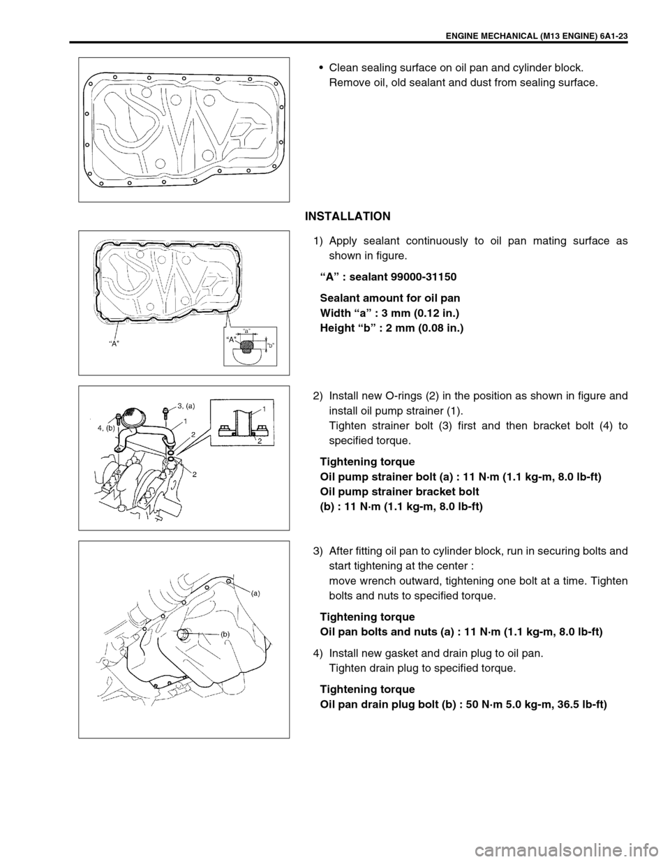
1) Apply sealant continuously to oil pan mating surface as
shown in figure.
“A” : sealant 99000-31150
Sealant amount for oil pan
Width “a” : 3 mm (0.12 in.)
Height “b” : 2 mm (0.08 in.)
2) Install new O-rings (2) in the position as shown in figure and
install oil pump strainer (1).
Tighten strainer bolt (3) first and then bracket bolt (4) to
specified torque.
Tightening torque
Oil pump strainer bolt (a) : 11 N·m (1.1 kg-m, 8.0 lb-ft)
Oil pump strainer bracket bolt
(b) : 11 N·m (1.1 kg-m, 8.0 lb-ft)
3) After fitting oil pan to cylinder block, run in securing bolts and
start tightening at the center :
move wrench outward, tightening one bolt at a time. Tighten
bolts and nuts to specified torque.
Tightening torque
Oil pan bolts and nuts (a) : 11 N·m (1.1 kg-m, 8.0 lb-ft)
4) Install new gasket and drain plug to oil pan.
Tighten drain plug to specified torque.
Tightening torque
Oil pan drain plug bolt (b) : 50 N·m 5.0 kg-m, 36.5 lb-ft)
Page 527 of 698
6A1-26 ENGINE MECHANICAL (M13 ENGINE)
3) Remove right side engine under cover (1).
4) Remove A/C compressor belt (3) (if equipped).
5) Remove water pump belt (1).
6) Remove water pump pulley (2).
7) Drain engine oil.
8) Remove crankshaft pulley bolt (2).
To lock crankshaft pulley (1), use special tool with it as
shown in figure.
Special tool
(A) : 09917-68221
9) Remove oil pan (1) referring to “OIL PAN AND OIL PUMP
STRAINER”.
10) Remove cylinder head cover referring to “CYLINDER HEAD
COVER”.
Page 528 of 698
ENGINE MECHANICAL (M13 ENGINE) 6A1-27
11) Support engine with supporting device (1).
12) Remove engine right side mounting (2) with bracket from
timing chain cover and body.
13) Remove timing chain cover (1).
CLEAN
Clean sealing surface on timing chain cover, cylinder block
and cylinder head.
Remove oil, old sealant and dust from sealing surface.
INSPECTION
Check oil seal (1) lip for fault or other damage.
Replace as necessary.
Special tool
(A) : 09913-75520
NOTE:
When installing new oil seal, tap it in until its surface is
flash with edge of timing chain cover (2).
To install oil seal, use special tool (Bearing installer).
Page 530 of 698
ENGINE MECHANICAL (M13 ENGINE) 6A1-29
5) Install cylinder head cover referring to “CYLINDER HEAD
COVER”.
6) Install oil pan (1) referring to “OIL PAN AND OIL PUMP
STRAINER”.
7) Install crankshaft pulley (1). Tighten bolt (2) to specified
torque. To lock crankshaft pulley, use special tool with it as
shown in the figure.
Special tool
(A) : 09917-68221
Tightening torque
Crankshaft pulley bolt (a) : 150 N·m (15.0 kg-m, 108.5 lb-ft)
8) Adjust water pump belt tension referring to Section 0B for
adjusting procedure.
9) Adjust A/C compressor belt tension (if equipped) referring to
Section 1B for adjusting procedure.
10) Install right side engine under cover.
11) Connect disconnected electric lead wires securely.
12) Refill engine with engine oil.
13) Verify that there is no oil leakage and exhaust gas leakage at
each connection.
Page 539 of 698

6A1-38 ENGINE MECHANICAL (M13 ENGINE)
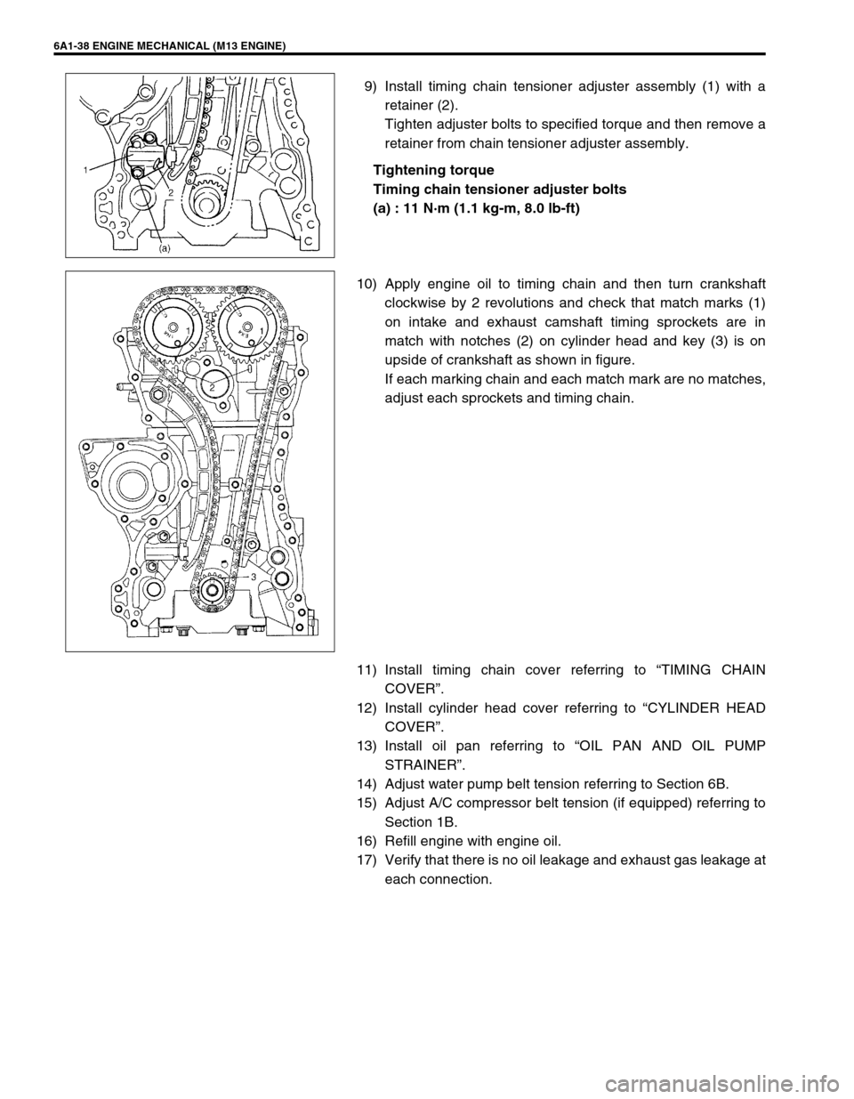
9) Install timing chain tensioner adjuster assembly (1) with a
retainer (2).
Tighten adjuster bolts to specified torque and then remove a
retainer from chain tensioner adjuster assembly.
Tightening torque
Timing chain tensioner adjuster bolts
(a) : 11 N·m (1.1 kg-m, 8.0 lb-ft)
10) Apply engine oil to timing chain and then turn crankshaft
clockwise by 2 revolutions and check that match marks (1)
on intake and exhaust camshaft timing sprockets are in
match with notches (2) on cylinder head and key (3) is on
upside of crankshaft as shown in figure.
If each marking chain and each match mark are no matches,
adjust each sprockets and timing chain.
11) Install timing chain cover referring to “TIMING CHAIN
COVER”.
12) Install cylinder head cover referring to “CYLINDER HEAD
COVER”.
13) Install oil pan referring to “OIL PAN AND OIL PUMP
STRAINER”.
14) Adjust water pump belt tension referring to Section 6B.
15) Adjust A/C compressor belt tension (if equipped) referring to
Section 1B.
16) Refill engine with engine oil.
17) Verify that there is no oil leakage and exhaust gas leakage at
each connection.