Page 541 of 698

6A1-40 ENGINE MECHANICAL (M13 ENGINE)
7) Remove tappets (2) with shims (1).
INSPECTION
Cam Wear
Using a micrometer, measure cam height “a”. If measured height
is below its limit, replace camshaft.
Cam height “a” of camshaft
Camshaft Runout
Set camshaft between two “V” blocks, and measure its runout by
using a dial gauge.
If measured runout exceeds below limit, replace camshaft.
Camshaft runout limit
: 0.10 mm (0.0039 in.)
Camshaft Journal Wear
Check camshaft journals and camshaft housings for pitting,
scratches, wear or damage.
If any malcondition is found, replace camshaft or cylinder head
with housing. Never replace cylinder head without replacing hous-
ings.
Check clearance by using gaging plastic. Checking procedure is
as follows.
1) Clean housings and camshaft journals.
2) Remove all tappets with shims.
3) Install camshafts to cylinder head.
4) Place a piece of gaging plastic to full width of journal of cam-
shaft (parallel to camshaft).
5) Install camshaft housing.
Standard Limit
Intake cam 44.919 – 45.089 mm
(1.768 – 1.775 in.)44.81 mm
(1.764 in.)
Exhaust cam
(ID mark (1) on
sprocket: EXA)44.202 – 44.362 mm
(1.740 – 1.747 in.)44.08 mm
(1.735 in.)
Exhaust cam
(ID mark (1) on
sprocket: EXB)44.399 – 44.559 mm
(1.748 – 1.754 in.)44.28 mm
(1.743 in.)
Page 550 of 698

ENGINE MECHANICAL (M13 ENGINE) 6A1-49
Valves
Remove all carbon from valves.
Inspect each valve for wear, burn or distortion at its face and
stem end, as necessary, replace it.
Measure thickness “a” of valve head. If measured thickness
exceeds limit, replace valve.
Valve head thickness (In and Ex)
Standard : 1.22 – 1.55 mm (0.048 – 0.061 in.)
Limit : 0.9 mm (0.035 in.)
Inspect valve stem end face for pitting and wear. If pitting or
wear is found there, valve stem end may be resurfaced, but
not too much to grind off its chamber. When it is worn out too
much that its chamber is gone, replace valve.
Check each valve for radial runout with a dial gauge and “V”
block. To check runout, rotate valve slowly. If runout exceeds
its limit, replace valve.
Limit on valve head radial runout
: 0.08 mm (0.003 in.)
Seating contact width:
Create contact pattern on each valve in the usual manner,
i.e. by giving uniform coat of marking compound to valve
seat and by rotatingly tapping seat with valve head. Valve
lapper (tool used in valve lapping) must be used.
Pattern produced on seating face of valve must be a continu-
ous ring without any break, and the width of pattern must be
within specified range.
Standard seating width “a” revealed by contact pattern on
valve face
In and Ex : 1.1 - 1.3 mm (0.0433 - 0.0512 in.)
Page 556 of 698

ENGINE MECHANICAL (M13 ENGINE) 6A1-55
7) Install valve spring and spring retainer.
Each valve spring has top end (large-pitch end (1)) and bot-
tom end (small-pitch end (2)). Be sure to position spring in
place with its bottom end (small-pitch end) facing the bottom
(valve spring seat side).
8) Using special tools (Valve lifter), compress valve spring and
fit two valve cotters (1) into groove in valve stem.
Special tool
(A) : 09916-14510
(B) : 09916-14910
(C) : 09916-84511
9) Install intake manifold, injectors and exhaust manifold to cyl-
inder head.
INSTALLATION
1) Clean mating surface of cylinder head and cylinder block.
Remove oil, old gasket and dust from mating surface.
2) Install knock pins (1) to cylinder block.
3) Install new cylinder head gasket (2) to cylinder block.
“TOP” mark provided on gasket comes to crankshaft pulley
side, facing up (toward cylinder head side).
4) Make sure that oil jet (venturi plug) (1) is installed and if it is,
that it is not clogged.
When installing it, be sure to tighten to specified torque.
Tightening torque
Venturi plug (a) : 5 N·m (0.5 kg-m, 3.5 lb-ft)
A : Valve spring retainer side
B : Valve spring seat side
NOTE:
When compressing the valve spring, be carefully to free
from damage in inside face of tappet installing hole.
Page 557 of 698

6A1-56 ENGINE MECHANICAL (M13 ENGINE)
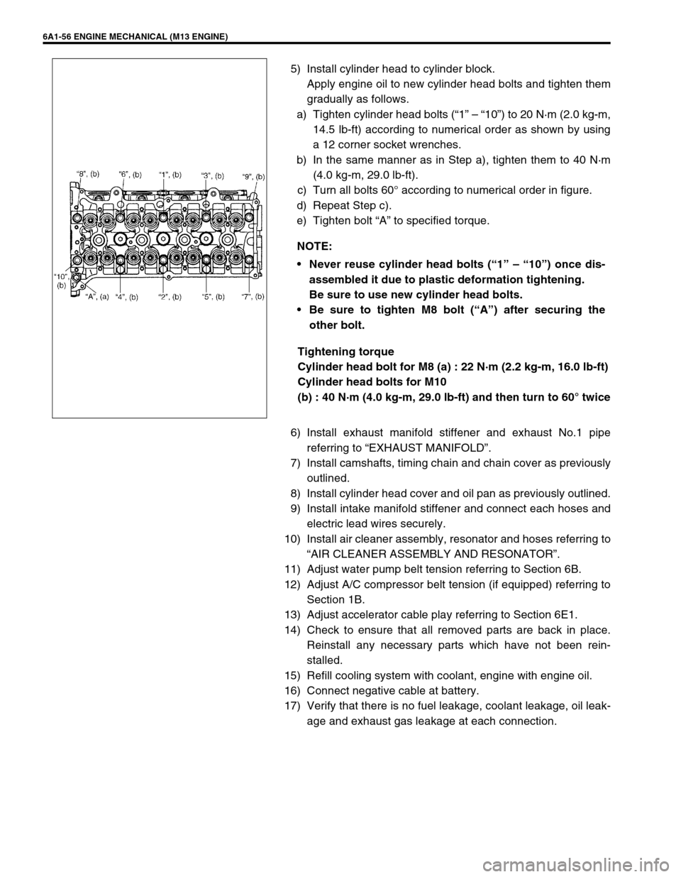
5) Install cylinder head to cylinder block.
Apply engine oil to new cylinder head bolts and tighten them
gradually as follows.
a) Tighten cylinder head bolts (“1” – “10”) to 20 N·m (2.0 kg-m,
14.5 lb-ft) according to numerical order as shown by using
a 12 corner socket wrenches.
b) In the same manner as in Step a), tighten them to 40 N·m
(4.0 kg-m, 29.0 lb-ft).
c) Turn all bolts 60° according to numerical order in figure.
d) Repeat Step c).
e) Tighten bolt “A” to specified torque.
Tightening torque
Cylinder head bolt for M8 (a) : 22 N·m (2.2 kg-m, 16.0 lb-ft)
Cylinder head bolts for M10
(b) : 40 N·m (4.0 kg-m, 29.0 lb-ft) and then turn to 60° twice
6) Install exhaust manifold stiffener and exhaust No.1 pipe
referring to “EXHAUST MANIFOLD”.
7) Install camshafts, timing chain and chain cover as previously
outlined.
8) Install cylinder head cover and oil pan as previously outlined.
9) Install intake manifold stiffener and connect each hoses and
electric lead wires securely.
10) Install air cleaner assembly, resonator and hoses referring to
“AIR CLEANER ASSEMBLY AND RESONATOR”.
11) Adjust water pump belt tension referring to Section 6B.
12) Adjust A/C compressor belt tension (if equipped) referring to
Section 1B.
13) Adjust accelerator cable play referring to Section 6E1.
14) Check to ensure that all removed parts are back in place.
Reinstall any necessary parts which have not been rein-
stalled.
15) Refill cooling system with coolant, engine with engine oil.
16) Connect negative cable at battery.
17) Verify that there is no fuel leakage, coolant leakage, oil leak-
age and exhaust gas leakage at each connection. NOTE:
Never reuse cylinder head bolts (“1” – “10”) once dis-
assembled it due to plastic deformation tightening.
Be sure to use new cylinder head bolts.
Be sure to tighten M8 bolt (“A”) after securing the
other bolt.
Page 566 of 698

ENGINE MECHANICAL (M13 ENGINE) 6A1-65
INSTALLATION
1) Apply engine oil to pistons, rings, cylinder walls, connecting
rod bearings and crankpins.
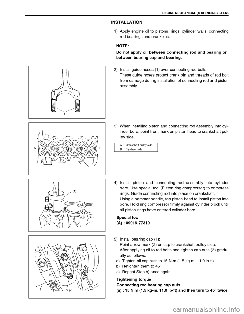
2) Install guide hoses (1) over connecting rod bolts.
These guide hoses protect crank pin and threads of rod bolt
from damage during installation of connecting rod and piston
assembly.
3) When installing piston and connecting rod assembly into cyl-
inder bore, point front mark on piston head to crankshaft pul-
ley side.
4) Install piston and connecting rod assembly into cylinder
bore. Use special tool (Piston ring compressor) to compress
rings. Guide connecting rod into place on crankshaft.
Using a hammer handle, tap piston head to install piston into
bore. Hold ring compressor firmly against cylinder block until
all piston rings have entered cylinder bore.
Special tool
(A) : 09916-77310
5) Install bearing cap (1):
Point arrow mark (2) on cap to crankshaft pulley side.
After applying oil to rod bolts and tighten cap nuts (3) gradu-
ally as follows.
a) Tighten all cap nuts to 15 N·m (1.5 kg-m, 11.0 lb-ft).
b) Retighten them to 45°.
c) Repeat Step b) once again.
Tightening torque
Connecting rod bearing cap nuts
(a) : 15 N·m (1.5 kg-m, 11.0 lb-ft) and then turn to 45° twice. NOTE:
Do not apply oil between connecting rod and bearing or
between bearing cap and bearing.
A : Crankshaft pulley side
B : Flywheel side
Page 570 of 698

ENGINE MECHANICAL (M13 ENGINE) 6A1-69
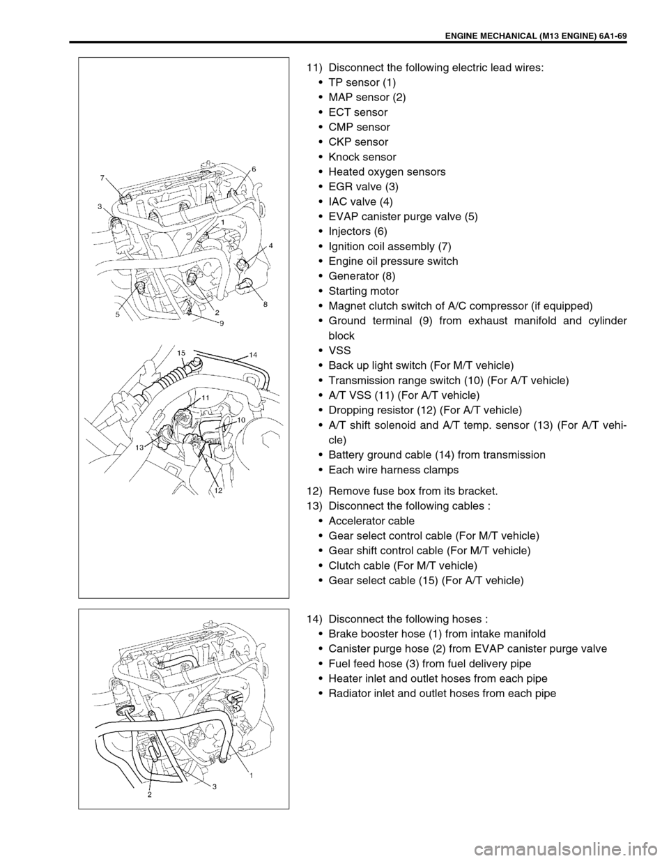
11) Disconnect the following electric lead wires:
TP sensor (1)
MAP sensor (2)
ECT sensor
CMP sensor
CKP sensor
Knock sensor
Heated oxygen sensors
EGR valve (3)
IAC valve (4)
EVAP canister purge valve (5)
Injectors (6)
Ignition coil assembly (7)
Engine oil pressure switch
Generator (8)
Starting motor
Magnet clutch switch of A/C compressor (if equipped)
Ground terminal (9) from exhaust manifold and cylinder
block
VSS
Back up light switch (For M/T vehicle)
Transmission range switch (10) (For A/T vehicle)
A/T VSS (11) (For A/T vehicle)
Dropping resistor (12) (For A/T vehicle)
A/T shift solenoid and A/T temp. sensor (13) (For A/T vehi-
cle)
Battery ground cable (14) from transmission
Each wire harness clamps
12) Remove fuse box from its bracket.
13) Disconnect the following cables :
Accelerator cable
Gear select control cable (For M/T vehicle)
Gear shift control cable (For M/T vehicle)
Clutch cable (For M/T vehicle)
Gear select cable (15) (For A/T vehicle)
14) Disconnect the following hoses :
Brake booster hose (1) from intake manifold
Canister purge hose (2) from EVAP canister purge valve
Fuel feed hose (3) from fuel delivery pipe
Heater inlet and outlet hoses from each pipe
Radiator inlet and outlet hoses from each pipe
Page 574 of 698
ENGINE MECHANICAL (M13 ENGINE) 6A1-73
MAIN BEARINGS, CRANKSHAFT AND CYLINDER BLOCK
Page 575 of 698

6A1-74 ENGINE MECHANICAL (M13 ENGINE)
REMOVAL
1) Remove engine assembly from vehicle as previously out-
lined.
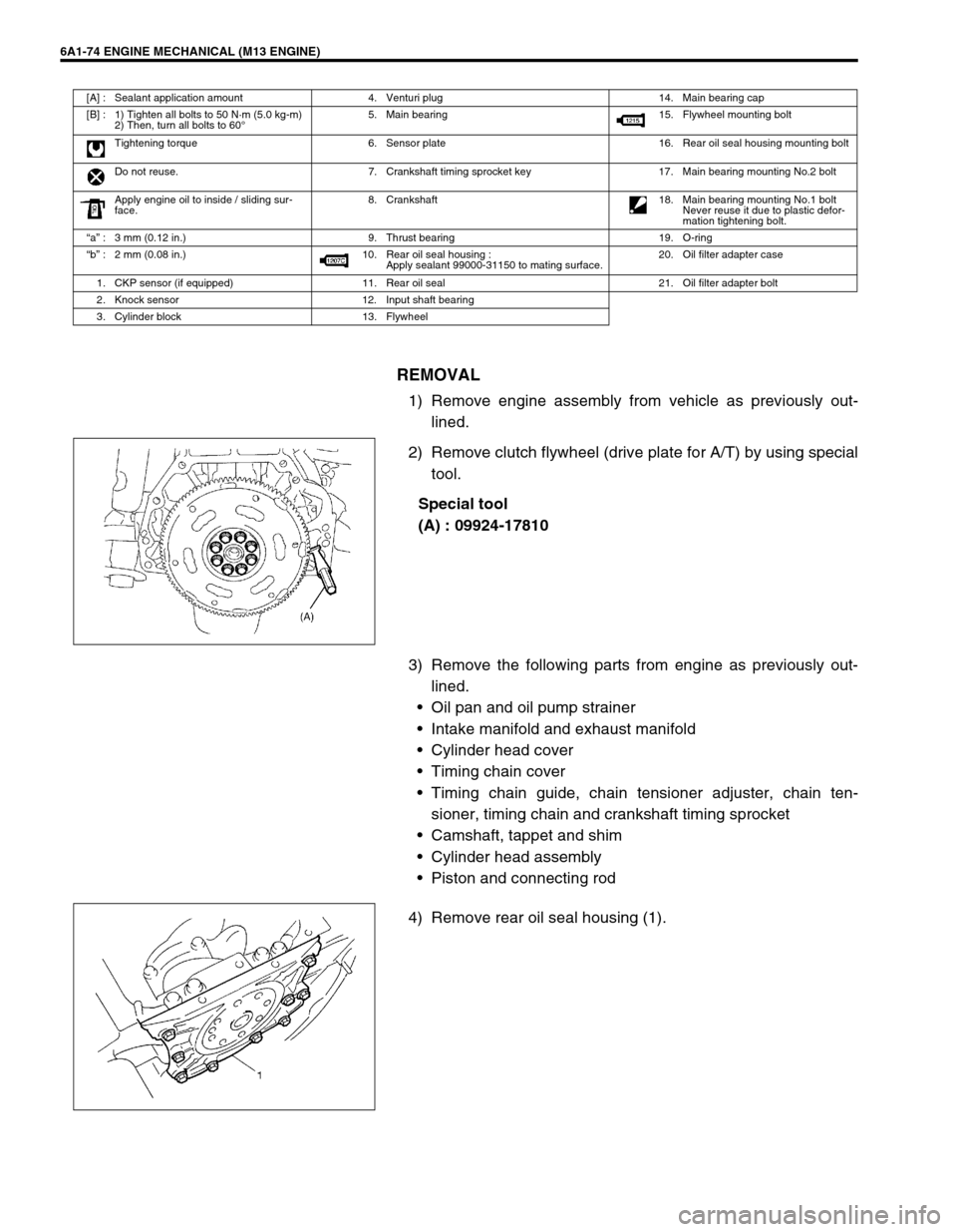
2) Remove clutch flywheel (drive plate for A/T) by using special
tool.
Special tool
(A) : 09924-17810
3) Remove the following parts from engine as previously out-
lined.
Oil pan and oil pump strainer
Intake manifold and exhaust manifold
Cylinder head cover
Timing chain cover
Timing chain guide, chain tensioner adjuster, chain ten-
sioner, timing chain and crankshaft timing sprocket
Camshaft, tappet and shim
Cylinder head assembly
Piston and connecting rod
4) Remove rear oil seal housing (1).
[A] : Sealant application amount 4. Venturi plug 14. Main bearing cap
[B] : 1) Tighten all bolts to 50 N·m (5.0 kg-m)
2) Then, turn all bolts to 60°5. Main bearing 15. Flywheel mounting bolt
Tightening torque 6. Sensor plate 16. Rear oil seal housing mounting bolt
Do not reuse. 7. Crankshaft timing sprocket key 17. Main bearing mounting No.2 bolt
Apply engine oil to inside / sliding sur-
face.8. Crankshaft
18. Main bearing mounting No.1 bolt
Never reuse it due to plastic defor-
mation tightening bolt.
“a” : 3 mm (0.12 in.) 9. Thrust bearing 19. O-ring
“b” : 2 mm (0.08 in.) 10. Rear oil seal housing :
Apply sealant 99000-31150 to mating surface.20. Oil filter adapter case
1. CKP sensor (if equipped) 11. Rear oil seal 21. Oil filter adapter bolt
2. Knock sensor 12. Input shaft bearing
3. Cylinder block 13. Flywheel