Page 586 of 698
ENGINE MECHANICAL (M13 ENGINE) 6A1-85
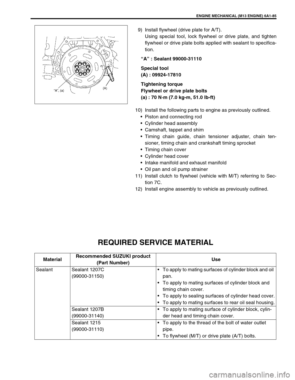
9) Install flywheel (drive plate for A/T).
Using special tool, lock flywheel or drive plate, and tighten
flywheel or drive plate bolts applied with sealant to specifica-
tion.
“A” : Sealant 99000-31110
Special tool
(A) : 09924-17810
Tightening torque
Flywheel or drive plate bolts
(a) : 70 N·m (7.0 kg-m, 51.0 lb-ft)
10) Install the following parts to engine as previously outlined.
Piston and connecting rod
Cylinder head assembly
Camshaft, tappet and shim
Timing chain guide, chain tensioner adjuster, chain ten-
sioner, timing chain and crankshaft timing sprocket
Timing chain cover
Cylinder head cover
Intake manifold and exhaust manifold
Oil pan and oil pump strainer
11) Install clutch to flywheel (vehicle with M/T) referring to Sec-
tion 7C.
12) Install engine assembly to vehicle as previously outlined.
REQUIRED SERVICE MATERIAL
MaterialRecommended SUZUKI product
(Part Number)Use
Sealant Sealant 1207C
(99000-31150)To apply to mating surfaces of cylinder block and oil
pan.
To apply to mating surfaces of cylinder block and
timing chain cover.
To apply to sealing surfaces of cylinder head cover.
To apply to mating surfaces to rear oil seal housing.
Sealant 1207B
(99000-31140)To apply to mating surface of cylinder block, cylin-
der head and timing chain cover.
Sealant 1215
(99000-31110)To apply to the thread of the bolt of water outlet
pipe.
To flywheel (M/T) or drive plate (A/T) bolts.
Page 589 of 698
6A1-88 ENGINE MECHANICAL (M13 ENGINE)
09916-37810 09916-38210 09916-44910 09916-46020
Reamer (6 mm) Reamer (11 mm) Valve guide remover Valve guide remover
09916-56011 09916-57350 09916-58210 09916-67020
Valve guide installer
attachmentValve guide installer han-
dleValve guide installer han-
dleTappet holder
09916-77310 09916-84511 09917-98221 09917-88240
Piston ring compressor Forceps Camshaft lock holder Valve guide installer
09917-88250 09917-98221 09924-17810
Valve guide installer Valve stem seal installer Flywheel holder
Page 591 of 698
6B-2 ENGINE COOLING
GENERAL DESCRIPTION
The cooling system consists of the radiator cap, radiator, coolant reservoir tank, hoses, water pump, cooling fan
and thermostat. The radiator is of tube-and-fin type.
COOLING SYSTEM CIRCULATION
While the engine is warmed up (thermostat closed), coolant circulates as follows.
When coolant is warmed up to normal temperature and the thermostat opens, coolant passes through the radi-
ator core to be cooled as well as the above flow circuit.
1. Radiator inlet hose 5. Water pump 9. Heater outlet hose
2. Radiator outlet hose 6. Throttle body (Fast idle control plunger) 10. Radiator
3. Water inlet pipe 7. Engine
4. Thermostat 8. Heater inlet hose
Water pump Cylinder block
Thermostat closedCylinder head Water intake pipeThrottle body
Heater unit
Page 596 of 698
ENGINE COOLING 6B-7
ENGINE COOLING SYSTEM INSPECTION
AND SERVICE
1) Check cooling system for leakage or damage.
2) Wash radiator cap and filler neck with clean water by remov-
ing radiator cap when engine is cold.
3) Check coolant for proper level and freeze protection.
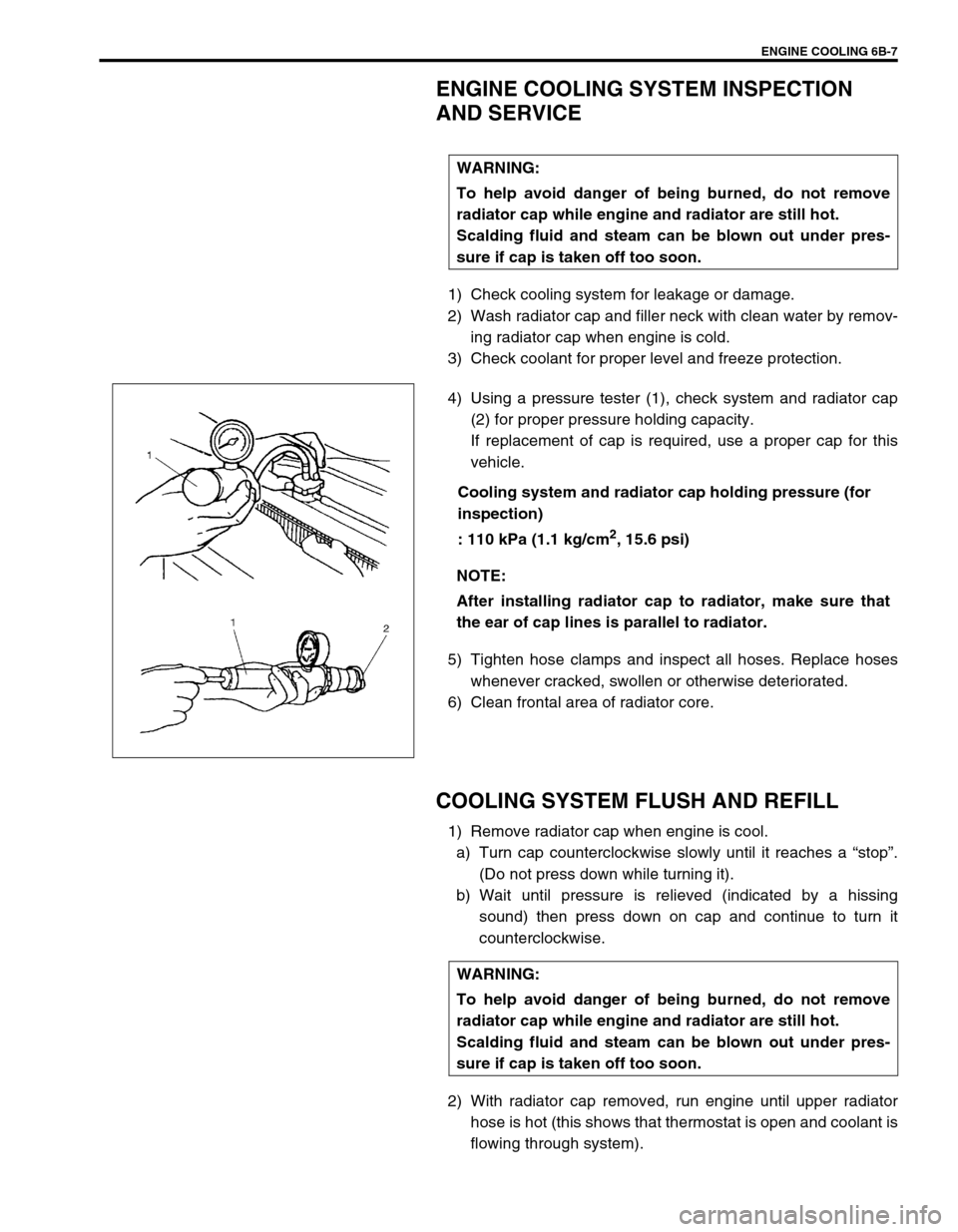
4) Using a pressure tester (1), check system and radiator cap
(2) for proper pressure holding capacity.
If replacement of cap is required, use a proper cap for this
vehicle.
Cooling system and radiator cap holding pressure (for
inspection)
: 110 kPa (1.1 kg/cm
2, 15.6 psi)
5) Tighten hose clamps and inspect all hoses. Replace hoses
whenever cracked, swollen or otherwise deteriorated.
6) Clean frontal area of radiator core.
COOLING SYSTEM FLUSH AND REFILL
1) Remove radiator cap when engine is cool.
a) Turn cap counterclockwise slowly until it reaches a “stop”.
(Do not press down while turning it).
b) Wait until pressure is relieved (indicated by a hissing
sound) then press down on cap and continue to turn it
counterclockwise.
2) With radiator cap removed, run engine until upper radiator
hose is hot (this shows that thermostat is open and coolant is
flowing through system). WARNING:
To help avoid danger of being burned, do not remove
radiator cap while engine and radiator are still hot.
Scalding fluid and steam can be blown out under pres-
sure if cap is taken off too soon.
NOTE:
After installing radiator cap to radiator, make sure that
the ear of cap lines is parallel to radiator.
WARNING:
To help avoid danger of being burned, do not remove
radiator cap while engine and radiator are still hot.
Scalding fluid and steam can be blown out under pres-
sure if cap is taken off too soon.
Page 606 of 698
ENGINE COOLING 6B-17
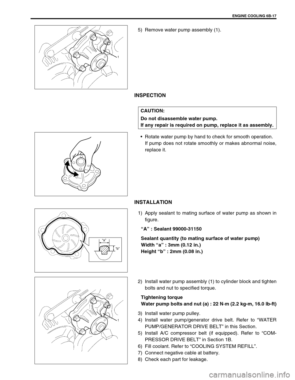
5) Remove water pump assembly (1).
INSPECTION
Rotate water pump by hand to check for smooth operation.
If pump does not rotate smoothly or makes abnormal noise,
replace it.
INSTALLATION
1) Apply sealant to mating surface of water pump as shown in
figure.
“A” : Sealant 99000-31150
Sealant quantity (to mating surface of water pump)
Width “a” : 3mm (0.12 in.)
Height “b” : 2mm (0.08 in.)
2) Install water pump assembly (1) to cylinder block and tighten
bolts and nut to specified torque.
Tightening torque
Water pump bolts and nut (a) : 22 N·m (2.2 kg-m, 16.0 lb-ft)
3) Install water pump pulley.
4) Install water pump/generator drive belt. Refer to “WATER
PUMP/GENERATOR DRIVE BELT” in this Section.
5) Install A/C compressor belt (if equipped). Refer to “COM-
PRESSOR DRIVE BELT” in Section 1B.
6) Fill coolant. Refer to “COOLING SYSTEM REFILL”.
7) Connect negative cable at battery.
8) Check each part for leakage.
CAUTION:
Do not disassemble water pump.
If any repair is required on pump, replace it as assembly.
“a”
“b”
Page 608 of 698
ENGINE FUEL 6C-1
6F1
6F2
6G
6C
6K
7A
7A1
7B1
7C1
7D
7E
7F
8A
8B
8C
8D
8E
9
10
10A
10B
SECTION 6C
ENGINE FUEL
CONTENTS
GENERAL DESCRIPTION .............................. 6C-1
ON-VEHICLE SERVICE .................................. 6C-2
COMPONENTS ........................................... 6C-2
PRECAUTIONS ........................................... 6C-3
FUEL LINES ................................................. 6C-4
FUEL PIPE ................................................... 6C-4
FUEL FILLER CAP ...................................... 6C-5FUEL TANK INLET VALVE ......................... 6C-6
FUEL TANK ................................................. 6C-7
FUEL PUMP ASSEMBLY .......................... 6C-10
DISASSEMBLY AND REASSEMBLY .... 6C-12
SPECIAL TOOL ............................................ 6C-14
TIGHTENING TORQUE SPECIFICATION.... 6C-14
GENERAL DESCRIPTION
The main components of the fuel system are fuel tank, fuel pump assembly (with fuel filter, fuel level gauge, fuel
pressure regulator and tank pressure control valve), fuel/vapor separator fuel feed line and fuel vapor line.
For the details of fuel flow and fuel vapor flow, refer to “GENERAL DESCRIPTION” in Section 6E. WARNING:
For vehicles equipped with Supplemental Restraint (Air Bag) System:
Service on and around the air bag system components or wiring must be performed only by an
authorized SUZUKI dealer. Refer to “Air Bag System Components and Wiring Location View” under
“General Description” in air bag system section in order to confirm whether you are performing ser-
vice on or near the air bag system components or wiring. Please observe all WARNINGS and “Ser-
vice Precautions” under “On-Vehicle Service” in air bag system section before performing service
on or around the air bag system components or wiring. Failure to follow WARNINGS could result in
unintentional activation of the system or could render the system inoperative. Either of these two
conditions may result in severe injury.
Technical service work must be started at least 90 seconds after the ignition switch is turned to the
“LOCK” position and the negative cable is disconnected from the battery. Otherwise, the system
may be activated by reserve energy in the Sensing and Diagnostic Module (SDM).
CAUTION:
The engine of this vehicle requires the use of unleaded fuel only. Use of leaded and/or low lead fuel
can result in engine damage and reduce the effectiveness of the emission control system.
Page 611 of 698
6C-4 ENGINE FUEL
FUEL LINES
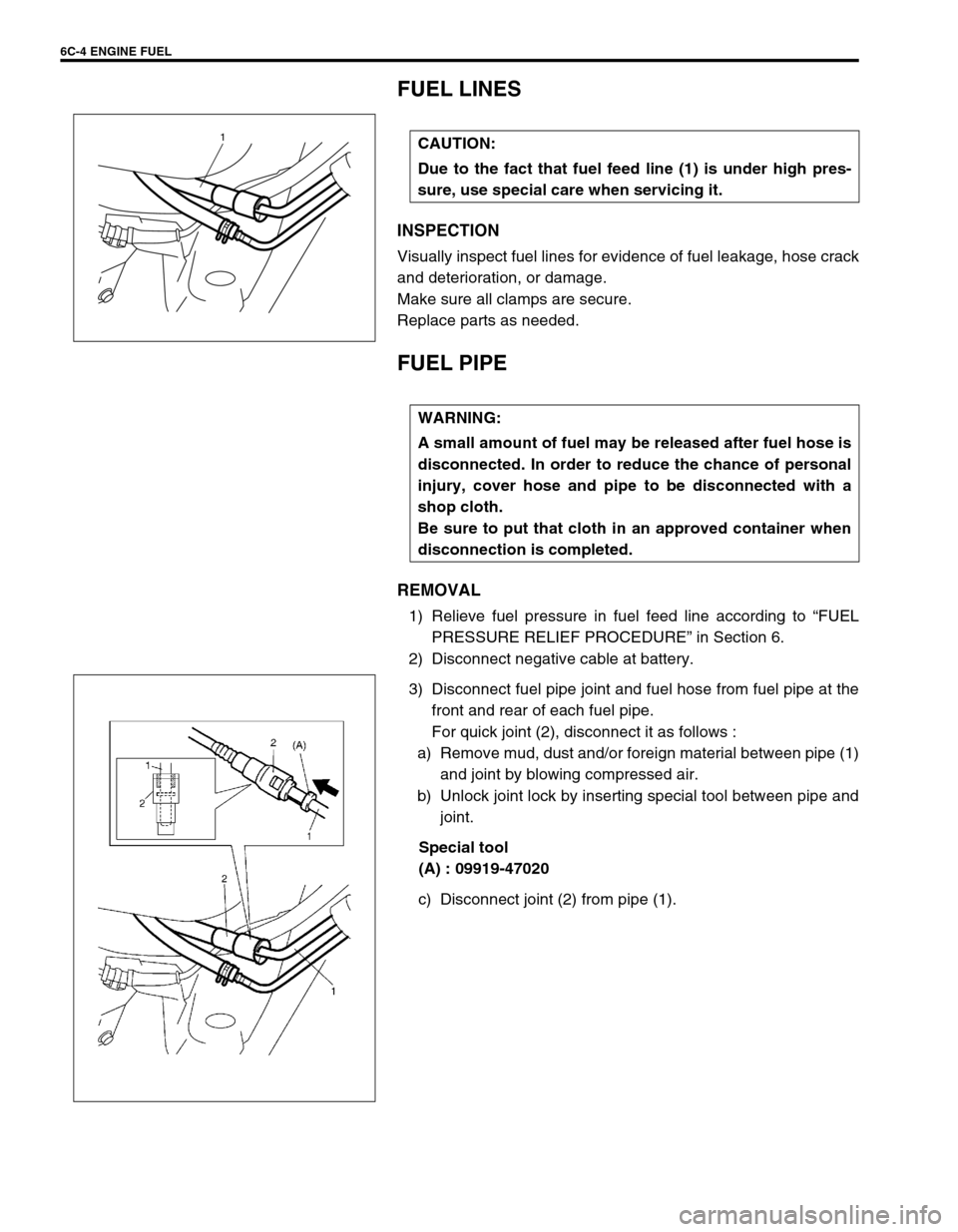
INSPECTION
Visually inspect fuel lines for evidence of fuel leakage, hose crack
and deterioration, or damage.
Make sure all clamps are secure.
Replace parts as needed.
FUEL PIPE
REMOVAL
1) Relieve fuel pressure in fuel feed line according to “FUEL
PRESSURE RELIEF PROCEDURE” in Section 6.
2) Disconnect negative cable at battery.
3) Disconnect fuel pipe joint and fuel hose from fuel pipe at the
front and rear of each fuel pipe.
For quick joint (2), disconnect it as follows :
a) Remove mud, dust and/or foreign material between pipe (1)
and joint by blowing compressed air.
b) Unlock joint lock by inserting special tool between pipe and
joint.
Special tool
(A) : 09919-47020
c) Disconnect joint (2) from pipe (1). CAUTION:
Due to the fact that fuel feed line (1) is under high pres-
sure, use special care when servicing it.
1
WARNING:
A small amount of fuel may be released after fuel hose is
disconnected. In order to reduce the chance of personal
injury, cover hose and pipe to be disconnected with a
shop cloth.
Be sure to put that cloth in an approved container when
disconnection is completed.
Page 612 of 698
ENGINE FUEL 6C-5
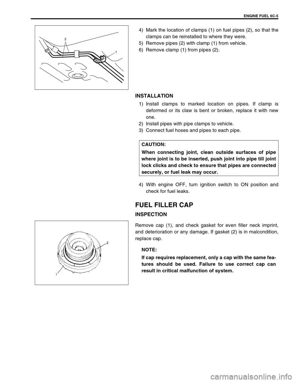
4) Mark the location of clamps (1) on fuel pipes (2), so that the
clamps can be reinstalled to where they were.
5) Remove pipes (2) with clamp (1) from vehicle.
6) Remove clamp (1) from pipes (2).
INSTALLATION
1) Install clamps to marked location on pipes. If clamp is
deformed or its claw is bent or broken, replace it with new
one.
2) Install pipes with pipe clamps to vehicle.
3) Connect fuel hoses and pipes to each pipe.
4) With engine OFF, turn ignition switch to ON position and
check for fuel leaks.
FUEL FILLER CAP
INSPECTION
Remove cap (1), and check gasket for even filler neck imprint,
and deterioration or any damage. If gasket (2) is in malcondition,
replace cap.
2
1
CAUTION:
When connecting joint, clean outside surfaces of pipe
where joint is to be inserted, push joint into pipe till joint
lock clicks and check to ensure that pipes are connected
securely, or fuel leak may occur.
NOTE:
If cap requires replacement, only a cap with the same fea-
tures should be used. Failure to use correct cap can
result in critical malfunction of system.