2000 SUZUKI SWIFT lock
[x] Cancel search: lockPage 615 of 698

6C-8 ENGINE FUEL
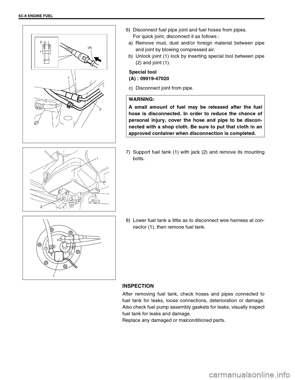
6) Disconnect fuel pipe joint and fuel hoses from pipes.
For quick joint, disconnect it as follows :
a) Remove mud, dust and/or foreign material between pipe
and joint by blowing compressed air.
b) Unlock joint (1) lock by inserting special tool between pipe
(2) and joint (1).
Special tool
(A) : 09919-47020
c) Disconnect joint from pipe.
7) Support fuel tank (1) with jack (2) and remove its mounting
bolts.
8) Lower fuel tank a little as to disconnect wire harness at con-
nector (1), then remove fuel tank.
INSPECTION
After removing fuel tank, check hoses and pipes connected to
fuel tank for leaks, loose connections, deterioration or damage.
Also check fuel pump assembly gaskets for leaks, visually inspect
fuel tank for leaks and damage.
Replace any damaged or malconditioned parts.WARNING:
A small amount of fuel may be released after the fuel
hose is disconnected. In order to reduce the chance of
personal injury, cover the hose and pipe to be discon-
nected with a shop cloth. Be sure to put that cloth in an
approved container when disconnection is completed.
1
Page 617 of 698

6C-10 ENGINE FUEL
5) Connect fuel feed hose (1) and vapor hose (2) to each pipe
as shown in figure and clamp them securely.
6) Connect negative cable at battery.
With engine OFF, turn ignition switch to ON position and
check for fuel leaks.
FUEL PUMP ASSEMBLY
REMOVAL
1) Remove fuel tank from vehicle. Refer to “FUEL TANK”.
2) Disconnect fuel breather hose (1), fuel vapor hose (2) and
pipes from fuel pump assembly.
When disconnecting joint of fuel feed line (3) from pipe,
unlock joint by inserting special tool between pipe and joint
lock first.
Special tool
(A) : 09919-47020 CAUTION:
When connecting joint, clean outside surfaces of pipe
where joint is to be inserted, push joint into pipe till
joint lock clicks and check to ensure that pipes are
connected securely, or fuel leak may occur.
Never let the fuel hoses touch the ABS sensor harness
(if equipped).
WARNING:
Refer to the PRECAUTIONS at the beginning of ON-VEHI-
CLE SERVICE.
1
23
Page 620 of 698

ENGINE FUEL 6C-13
INSTALLATION
1) Clean mating surfaces of fuel pump assembly (1) and fuel
tank.
2) Put plate (2) on fuel pump assembly (1) by matching the pro-
trusion of fuel pump assembly (3) to plate hole (4) as shown.
3) Install new gasket (2) and fuel pump assembly (1) with plate
(3) to fuel tank.
Tightening torque
Fuel pump assembly bolts (a) : 10 N·m (1.0 kg-m, 7.5 lb-ft)
4) Connect fuel breather hose (1), fuel vapor hose (2) and fuel
feed line (3) (pipe joint) to fuel pump assembly.
5) Install fuel tank (1) to vehicle. Refer to “FUEL TANK” in this
section.
3 2
4 43
1
3
1
2
(a)
CAUTION:
When connecting joint, clean outside surface of pipe
where joint is to be inserted, push joint into pipe till joint
lock clicks and check to ensure that pipes are connected
securely, or fuel leak may occur.1
23
Page 622 of 698

ENGINE AND EMISSION CONTROL SYSTEM 6E1-1
6F1
6F2
6G
6H
6E1
7A
7A1
7B1
7C1
7D
7E
7F
8A
8B
8C
8D
8E
9
10
10A
10B
SECTION 6E1
ENGINE AND EMISSION CONTROL SYSTEM
CONTENTS
GENERAL DESCRIPTION ............................ 6E1-2
AIR INTAKE SYSTEM ............................... 6E1-5
FUEL DELIVERY SYSTEM ....................... 6E1-6
FUEL PUMP ........................................... 6E1-6
ELECTRONIC CONTROL SYSTEM .......... 6E1-7
ENGINE & EMISSION CONTROL
INPUT/OUTPUT TABLE ........................ 6E1-8
ECM INPUT/OUTPUT CIRCUIT
DIAGRAM............................................... 6E1-9
ECM TERMINAL ARRANGEMENT
TABLE .................................................. 6E1-13
ON-VEHICLE SERVICE .............................. 6E1-15
ACCELERATOR CABLE
ADJUSTMENT ..................................... 6E1-15
IDLE SPEED/IDLE AIR CONTROL
(IAC) DUTY INSPECTION ................... 6E1-15
IDLE MIXTURE INSPECTION /
ADJUSTMENT (VEHICLE WITHOUT
HEATED OXYGEN SENSOR) ............. 6E1-17
AIR INTAKE SYSTEM ............................. 6E1-18
THROTTLE BODY ............................... 6E1-18IDLE AIR CONTROL VALVE (IAC
VALVE) ................................................ 6E1-20
FUEL DELIVERY SYSTEM ..................... 6E1-21
FUEL PRESSURE INSPECTION ........ 6E1-21
FUEL PUMP WITH PRESSURE
REGULATOR ....................................... 6E1-22
FUEL INJECTOR ................................. 6E1-23
ELECTRONIC CONTROL SYSTEM ....... 6E1-27
ENGINE CONTROL MODULE
(ECM) ................................................... 6E1-27
MANIFOLD ABSOLUTE PRESSURE
SENSOR (MAP SENSOR)................... 6E1-27
THROTTLE POSITION SENSOR (TP
SENSOR) ............................................. 6E1-28
INTAKE AIR TEMPERATURE
SENSOR (IAT SENSOR) ..................... 6E1-29
ENGINE COOLANT TEMPERATURE
SENSOR (ECT SENSOR) ................... 6E1-30
HEATED OXYGEN SENSOR (HO2S-1
AND HO2S-2) ...................................... 6E1-31
CAMSHAFT POSITION SENSOR ....... 6E1-32 WARNING:
For vehicles equipped with Supplemental Restraint (Air Bag) System :
Service on and around the air bag system components or wiring must be performed only by an
authorized SUZUKI dealer. Refer to “Air Bag System Components and Wiring Location View” under
“General Description” in air bag system section in order to confirm whether you are performing ser-
vice on or near the air bag system components or wiring. Please observe all WARNINGS and “Ser-
vice Precautions” under “On-Vehicle Service” in air bag system section before performing service
on or around the air bag system components or wiring. Failure to follow WARNINGS could result in
unintentional activation of the system or could render the system inoperative. Either of these two
conditions may result in severe injury.
Technical service work must be started at least 90 seconds after the ignition switch is turned to the
“LOCK” position and the negative cable is disconnected from the battery. Otherwise, the system
may be activated by reserve energy in the Sensing and Diagnostic Module (SDM).
NOTE:
Whether the following system (parts) are used in the particular vehicle or not depends on vehicle
specifications. Be sure to bear this in mind when performing service work.
EGR valve
Heated oxygen sensor(s) or CO adjusting resistor
Three way catalytic converter
Immobilizer indicator lamp
Knock sensor
Page 636 of 698

ENGINE AND EMISSION CONTROL SYSTEM 6E1-15
ON-VEHICLE SERVICE
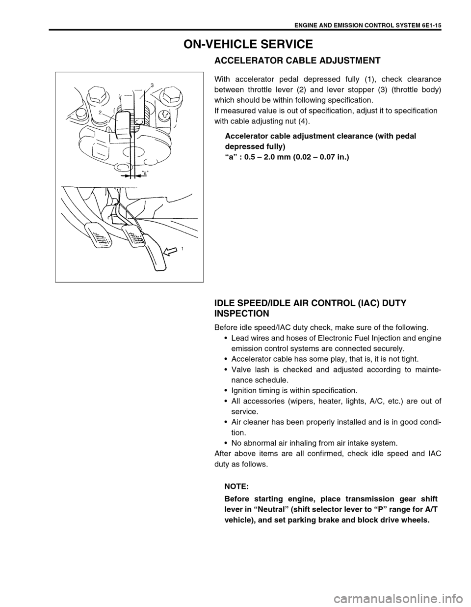
ACCELERATOR CABLE ADJUSTMENT
With accelerator pedal depressed fully (1), check clearance
between throttle lever (2) and lever stopper (3) (throttle body)
which should be within following specification.
If measured value is out of specification, adjust it to specification
with cable adjusting nut (4).
Accelerator cable adjustment clearance (with pedal
depressed fully)
“a” : 0.5 – 2.0 mm (0.02 – 0.07 in.)
IDLE SPEED/IDLE AIR CONTROL (IAC) DUTY
INSPECTION
Before idle speed/IAC duty check, make sure of the following.
Lead wires and hoses of Electronic Fuel Injection and engine
emission control systems are connected securely.
Accelerator cable has some play, that is, it is not tight.
Valve lash is checked and adjusted according to mainte-
nance schedule.
Ignition timing is within specification.
All accessories (wipers, heater, lights, A/C, etc.) are out of
service.
Air cleaner has been properly installed and is in good condi-
tion.
No abnormal air inhaling from air intake system.
After above items are all confirmed, check idle speed and IAC
duty as follows.
NOTE:
Before starting engine, place transmission gear shift
lever in “Neutral” (shift selector lever to “P” range for A/T
vehicle), and set parking brake and block drive wheels.
Page 649 of 698

6E1-28 ENGINE AND EMISSION CONTROL SYSTEM
THROTTLE POSITION SENSOR (TP SENSOR)
INSPECTION
1) Disconnect negative cable at battery and connector from IAT
sensor.
2) Remove air cleaner assembly with air cleaner outlet hose
and disconnect TP sensor connector.
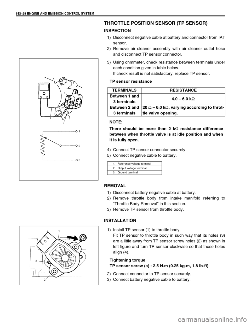
3) Using ohmmeter, check resistance between terminals under
each condition given in table below.
If check result is not satisfactory, replace TP sensor.
TP sensor resistance
4) Connect TP sensor connector securely.
5) Connect negative cable to battery.
REMOVAL
1) Disconnect battery negative cable at battery.
2) Remove throttle body from intake manifold referring to
“Throttle Body Removal” in this section.
3) Remove TP sensor from throttle body.
INSTALLATION
1) Install TP sensor (1) to throttle body.
Fit TP sensor to throttle body in such way that its holes (3)
are a little away from TP sensor screw holes (2) as shown in
left figure and turn TP sensor clockwise so that those holes
align (4).
Tightening torque
TP sensor screw (a) : 2.5 N·m (0.25 kg-m, 1.8 lb-ft)
2) Connect connector to TP sensor securely.
3) Connect battery negative cable to battery.TERMINALS RESISTANCE
Between 1 and
3 terminals4.0 – 6.0 k
Ω
Between 2 and
3 terminals20
Ω – 6.0 k
Ω, varying according to throt-
tle valve opening.
NOTE:
There should be more than 2 k
Ω resistance difference
between when throttle valve is at idle position and when
it is fully open.
1. Reference voltage terminal
2. Output voltage terminal
3. Ground terminal
Page 653 of 698

6E1-32 ENGINE AND EMISSION CONTROL SYSTEM
CAMSHAFT POSITION SENSOR
INSPECTION
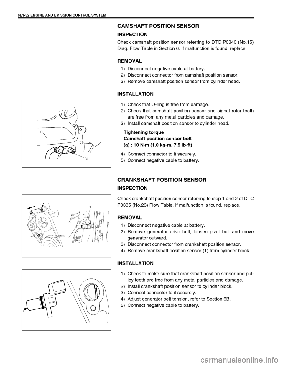
Check camshaft position sensor referring to DTC P0340 (No.15)
Diag. Flow Table in Section 6. If malfunction is found, replace.
REMOVAL
1) Disconnect negative cable at battery.
2) Disconnect connector from camshaft position sensor.
3) Remove camshaft position sensor from cylinder head.
INSTALLATION
1) Check that O-ring is free from damage.
2) Check that camshaft position sensor and signal rotor teeth
are free from any metal particles and damage.
3) Install camshaft position sensor to cylinder head.
Tightening torque
Camshaft position sensor bolt
(a) : 10 N·m (1.0 kg-m, 7.5 lb-ft)
4) Connect connector to it securely.
5) Connect negative cable to battery.
CRANKSHAFT POSITION SENSOR
INSPECTION
Check crankshaft position sensor referring to step 1 and 2 of DTC
P0335 (No.23) Flow Table. If malfunction is found, replace.
REMOVAL
1) Disconnect negative cable at battery.
2) Remove generator drive belt, loosen pivot bolt and move
generator outward.
3) Disconnect connector from crankshaft position sensor.
4) Remove crankshaft position sensor (1) from cylinder block.
INSTALLATION
1) Check to make sure that crankshaft position sensor and pul-
ley teeth are free from any metal particles and damage.
2) Install crankshaft position sensor to cylinder block.
3) Connect connector to it securely.
4) Adjust generator belt tension, refer to Section 6B.
5) Connect negative cable to battery.
Page 663 of 698

IGNITION SYSTEM (ELECTRONIC IGNITION SYSTEM) 6F1-1
6G
6F2
6G
6H
6K
6F1
7A
7A1
7A1
7D
7E
7F
8A
8B
8C
8D
8E
9
10
10A
10B
SECTION 6F1
IGNITION SYSTEM
(ELECTRONIC IGNITION SYSTEM)
CONTENTS
GENERAL DESCRIPTION ............................. 6F1-2
DIAGNOSIS .................................................... 6F1-3
ON-VEHICLE SERVICE ................................. 6F1-5
IGNITION SPARK TEST ............................. 6F1-5
HIGH-TENSION CORDS ............................ 6F1-5
SPARK PLUGS ........................................... 6F1-6IGNITION COIL ASSEMBLY
(INCLUDING IGNITOR) .............................. 6F1-7
CRANKSHAFT POSITION SENSOR
(CKP SENSOR) .......................................... 6F1-7
IGNITION TIMING ...................................... 6F1-8
SPECIAL TOOL ............................................. 6F1-9
WARNING:
For vehicles equipped with Supplemental Restraint (Air Bag) System:
Service on and around the air bag system components or wiring must be performed only by an
authorized SUZUKI dealer. Refer to “Air Bag System Components and Wiring Location View” under
“General Description” in air bag system section in order to confirm whether you are performing ser-
vice on or near the air bag system components or wiring. Please observe all WARNINGS and “Ser-
vice Precautions” under “On-Vehicle Service” in air bag system section before performing service
on or around the air bag system components or wiring. Failure to follow WARNINGS could result in
unintentional activation of the system or could render the system inoperative. Either of these two
conditions may result in severe injury.
Technical service work must be started at least 90 seconds after the ignition switch is turned to the
“LOCK” position and the negative cable is disconnected from the battery. Otherwise, the system
may be activated by reserve energy in the Sensing and Diagnostic Module (SDM).