Page 655 of 698

6E1-34 ENGINE AND EMISSION CONTROL SYSTEM
FUEL CUT OPERATION
INSPECTION
1) Warm up engine to normal operating temperature.
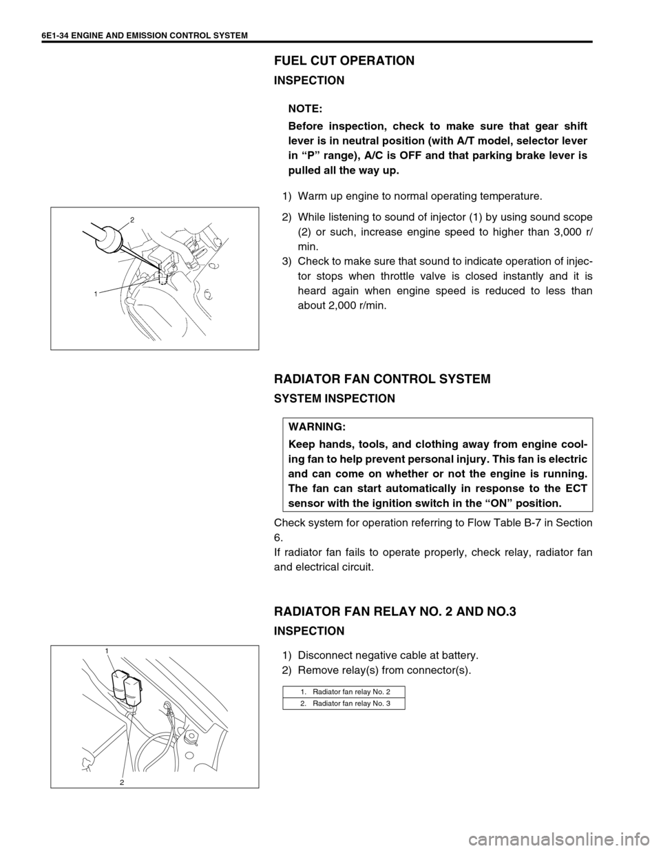
2) While listening to sound of injector (1) by using sound scope
(2) or such, increase engine speed to higher than 3,000 r/
min.
3) Check to make sure that sound to indicate operation of injec-
tor stops when throttle valve is closed instantly and it is
heard again when engine speed is reduced to less than
about 2,000 r/min.
RADIATOR FAN CONTROL SYSTEM
SYSTEM INSPECTION
Check system for operation referring to Flow Table B-7 in Section
6.
If radiator fan fails to operate properly, check relay, radiator fan
and electrical circuit.
RADIATOR FAN RELAY NO. 2 AND NO.3
INSPECTION
1) Disconnect negative cable at battery.
2) Remove relay(s) from connector(s).NOTE:
Before inspection, check to make sure that gear shift
lever is in neutral position (with A/T model, selector lever
in “P” range), A/C is OFF and that parking brake lever is
pulled all the way up.
WARNING:
Keep hands, tools, and clothing away from engine cool-
ing fan to help prevent personal injury. This fan is electric
and can come on whether or not the engine is running.
The fan can start automatically in response to the ECT
sensor with the ignition switch in the “ON” position.
1. Radiator fan relay No. 2
2. Radiator fan relay No. 3
1
2
Page 660 of 698

ENGINE AND EMISSION CONTROL SYSTEM 6E1-39
EVAP CANISTER INSPECTION
1) Check outside of EVAP canister visually.
2) Disconnect vacuum hoses from EVAP canister.
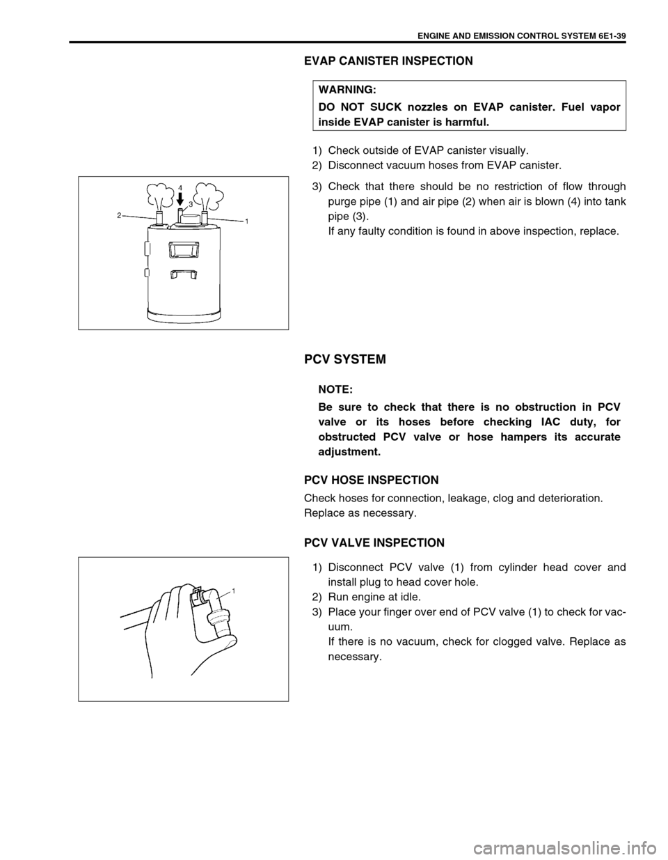
3) Check that there should be no restriction of flow through
purge pipe (1) and air pipe (2) when air is blown (4) into tank
pipe (3).
If any faulty condition is found in above inspection, replace.
PCV SYSTEM
PCV HOSE INSPECTION
Check hoses for connection, leakage, clog and deterioration.
Replace as necessary.
PCV VALVE INSPECTION
1) Disconnect PCV valve (1) from cylinder head cover and
install plug to head cover hole.
2) Run engine at idle.
3) Place your finger over end of PCV valve (1) to check for vac-
uum.
If there is no vacuum, check for clogged valve. Replace as
necessary. WARNING:
DO NOT SUCK nozzles on EVAP canister. Fuel vapor
inside EVAP canister is harmful.
NOTE:
Be sure to check that there is no obstruction in PCV
valve or its hoses before checking IAC duty, for
obstructed PCV valve or hose hampers its accurate
adjustment.
Page 665 of 698

IGNITION SYSTEM (ELECTRONIC IGNITION SYSTEM 6F1-3
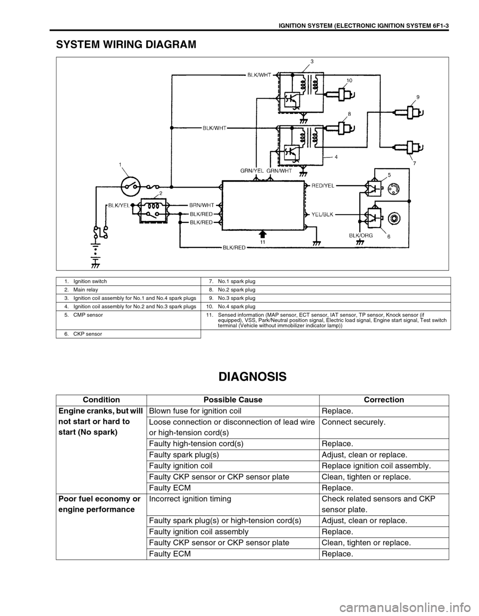
SYSTEM WIRING DIAGRAM
DIAGNOSIS
1. Ignition switch 7. No.1 spark plug
2. Main relay 8. No.2 spark plug
3. Ignition coil assembly for No.1 and No.4 spark plugs 9. No.3 spark plug
4. Ignition coil assembly for No.2 and No.3 spark plugs 10. No.4 spark plug
5. CMP sensor 11. Sensed information (MAP sensor, ECT sensor, IAT sensor, TP sensor, Knock sensor (if
equipped), VSS, Park/Neutral position signal, Electric load signal, Engine start signal, Test switch
terminal (Vehicle without immobilizer indicator lamp))
6. CKP sensor
Condition Possible Cause Correction
Engine cranks, but will
not start or hard to
start (No spark)Blown fuse for ignition coil Replace.
Loose connection or disconnection of lead wire
or high-tension cord(s)Connect securely.
Faulty high-tension cord(s) Replace.
Faulty spark plug(s) Adjust, clean or replace.
Faulty ignition coil Replace ignition coil assembly.
Faulty CKP sensor or CKP sensor plate Clean, tighten or replace.
Faulty ECM Replace.
Poor fuel economy or
engine performanceIncorrect ignition timing Check related sensors and CKP
sensor plate.
Faulty spark plug(s) or high-tension cord(s) Adjust, clean or replace.
Faulty ignition coil assembly Replace.
Faulty CKP sensor or CKP sensor plate Clean, tighten or replace.
Faulty ECM Replace.