2000 NISSAN PATROL Fuel
[x] Cancel search: FuelPage 260 of 1033
REMOVAL
1. Remove the following:
+Engine coolant draining
+Charge air cooler
+Air inlet pipe
+Throttle body
+Rocker cover
+Oil level gauge guide
+EGR guide tube
+EGR volume control solenoid valve
+Fuel hose
+Injection tube
+Radiator upper hose
+Radiator shroud
+Cooling fan
+Drive belt
+Vacuum pipe
+Vacuum pump
2. Move the power steering pump.
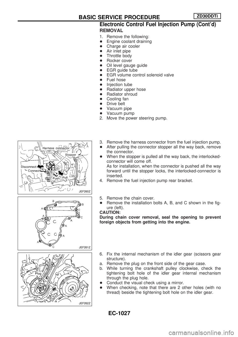
3. Remove the harness connector from the fuel injection pump.
+After pulling the connector stopper all the way back, remove
the connector.
+When the stopper is pulled all the way back, the interlocked-
connector will come off.
As for installation, when the connector is pushed all the way
forward until the stopper locks, the interlocked-connector is
inserted.
4. Remove the fuel injection pump rear bracket.
5. Remove the chain cover.
+Remove the installation bolts A, B, and C shown in the fig-
ure (left).
CAUTION:
During chain cover removal, seal the opening to prevent
foreign objects from getting into the engine.
6. Fix the internal mechanism of the idler gear (scissors gear
structure).
a. Remove the plug on the front side of the gear case.
b. While turning the crankshaft pulley clockwise, check the
tightening bolt hole of the idler gear internal mechanism
through the plug hole.
+Conduct the visual check using a mirror.
+When checking, note that there are 2 other holes (with no
thread) beside the tightening bolt hole on the idler gear.
JEF260Z
JEF261Z
JEF262Z
BASIC SERVICE PROCEDUREZD30DDTi
Electronic Control Fuel Injection Pump (Cont'd)
EC-1027
Page 261 of 1033
![NISSAN PATROL 2000 Electronic Repair Manual c. Install the tightening bolt [Part No.: 81-20620-28, thread
diameter: M6, under head: 20 mm (0.79 in), pitch: 1.0 mm
(0.039 in)] to the idler gear tightening bolt hole, and tighten
to the specified NISSAN PATROL 2000 Electronic Repair Manual c. Install the tightening bolt [Part No.: 81-20620-28, thread
diameter: M6, under head: 20 mm (0.79 in), pitch: 1.0 mm
(0.039 in)] to the idler gear tightening bolt hole, and tighten
to the specified](/manual-img/5/57367/w960_57367-260.png)
c. Install the tightening bolt [Part No.: 81-20620-28, thread
diameter: M6, under head: 20 mm (0.79 in), pitch: 1.0 mm
(0.039 in)] to the idler gear tightening bolt hole, and tighten
to the specified torque:
: 2.5 - 3.4 Nzm (0.25 - 0.35 kg-m, 22 - 30 in-lb)
CAUTION:
+To protect the idler gear from damage, do not use the
substitute part for the tightening bolt.
+Hereafter, do not turn the crankshaft to avoid hitting
tightening bolt head against the gear case.
+Do not remove the idler gear tightening bolt before
installations of the timing chain and related parts are
completed.
7. Make mating marks on the cam sprocket, fuel injection pump
sprocket, and timing chain with paint.
8. Make mating marks on the fuel injection pump gear and idler
gear with paint.
9. Remove the chain tensioner.
(1) Loosen the upper and lower installation bolts.
(2) While holding the chain tensioner by hand, remove the upper
installation bolt to release the spring tension.
(3) Remove the lower installation bolt first, and then the chain
tensioner.
+Since the chain tensioner does not have a mechanism to
prevent the plunger pop-out, watch out for the fall of the
plunger and spring. (Return prevention mechanism is avail-
able.)
10. Remove the timing chain slack guide.
11. Remove the cam sprocket and timing chain at the same time.
+Make mating marks on each sprocket and timing chain.
+Hold the hexagon head of the camshaft on the exhaust mani-
fold side, and loosen the cam sprocket installation bolt.
CAUTION:
Do not loosen the installation bolt using a chain tension.
12. Remove the fuel injection pump sprocket and gear as an
assembly.
+Fix the fuel injection pump gear with the pulley holder (SST),
and loosen the installation bolt for removal.
+Try not to move the pump shaft when removing.
+Connect the sprocket and gear with a dowel pin, and tighten
them together with the installation bolt.
JEF263Z
JEF264Z
JEF265Z
JEF266Z
JEF267Z
BASIC SERVICE PROCEDUREZD30DDTi
Electronic Control Fuel Injection Pump (Cont'd)
EC-1028
Page 262 of 1033
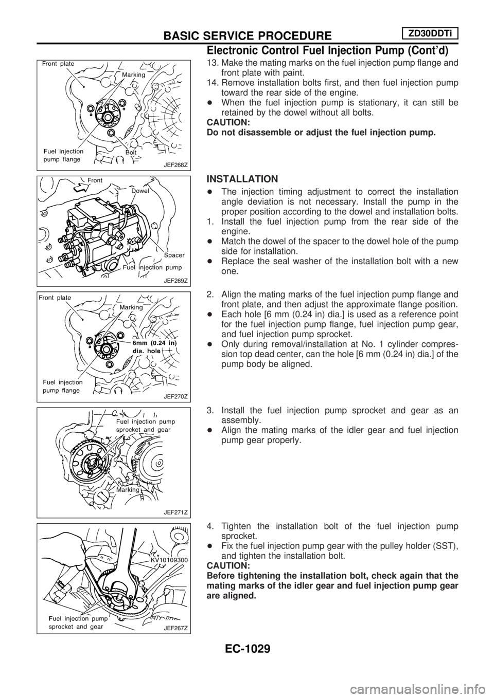
13. Make the mating marks on the fuel injection pump flange and
front plate with paint.
14. Remove installation bolts first, and then fuel injection pump
toward the rear side of the engine.
+When the fuel injection pump is stationary, it can still be
retained by the dowel without all bolts.
CAUTION:
Do not disassemble or adjust the fuel injection pump.
INSTALLATION
+The injection timing adjustment to correct the installation
angle deviation is not necessary. Install the pump in the
proper position according to the dowel and installation bolts.
1. Install the fuel injection pump from the rear side of the
engine.
+Match the dowel of the spacer to the dowel hole of the pump
side for installation.
+Replace the seal washer of the installation bolt with a new
one.
2. Align the mating marks of the fuel injection pump flange and
front plate, and then adjust the approximate flange position.
+Each hole [6 mm (0.24 in) dia.] is used as a reference point
for the fuel injection pump flange, fuel injection pump gear,
and fuel injection pump sprocket.
+Only during removal/installation at No. 1 cylinder compres-
sion top dead center, can the hole [6 mm (0.24 in) dia.] of the
pump body be aligned.
3. Install the fuel injection pump sprocket and gear as an
assembly.
+Align the mating marks of the idler gear and fuel injection
pump gear properly.
4. Tighten the installation bolt of the fuel injection pump
sprocket.
+Fix the fuel injection pump gear with the pulley holder (SST),
and tighten the installation bolt.
CAUTION:
Before tightening the installation bolt, check again that the
mating marks of the idler gear and fuel injection pump gear
are aligned.
JEF268Z
JEF269Z
JEF270Z
JEF271Z
JEF267Z
BASIC SERVICE PROCEDUREZD30DDTi
Electronic Control Fuel Injection Pump (Cont'd)
EC-1029
Page 263 of 1033
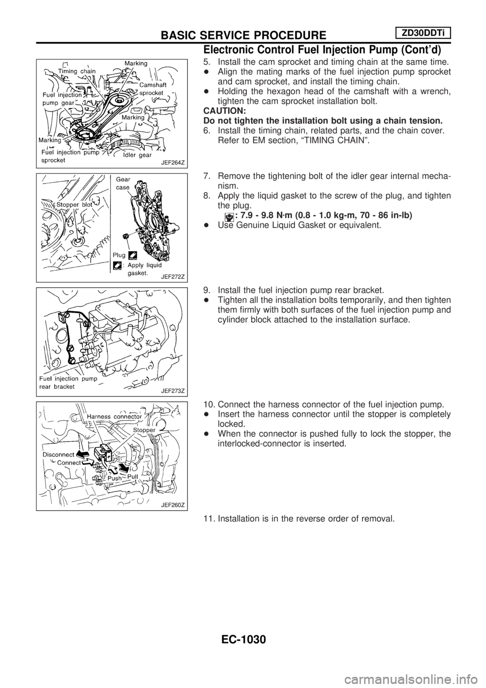
5. Install the cam sprocket and timing chain at the same time.
+Align the mating marks of the fuel injection pump sprocket
and cam sprocket, and install the timing chain.
+Holding the hexagon head of the camshaft with a wrench,
tighten the cam sprocket installation bolt.
CAUTION:
Do not tighten the installation bolt using a chain tension.
6. Install the timing chain, related parts, and the chain cover.
Refer to EM section, ªTIMING CHAINº.
7. Remove the tightening bolt of the idler gear internal mecha-
nism.
8. Apply the liquid gasket to the screw of the plug, and tighten
the plug.
: 7.9 - 9.8 Nzm (0.8 - 1.0 kg-m, 70 - 86 in-lb)
+Use Genuine Liquid Gasket or equivalent.
9. Install the fuel injection pump rear bracket.
+Tighten all the installation bolts temporarily, and then tighten
them firmly with both surfaces of the fuel injection pump and
cylinder block attached to the installation surface.
10. Connect the harness connector of the fuel injection pump.
+Insert the harness connector until the stopper is completely
locked.
+When the connector is pushed fully to lock the stopper, the
interlocked-connector is inserted.
11. Installation is in the reverse order of removal.
JEF264Z
JEF272Z
JEF273Z
JEF260Z
BASIC SERVICE PROCEDUREZD30DDTi
Electronic Control Fuel Injection Pump (Cont'd)
EC-1030
Page 264 of 1033
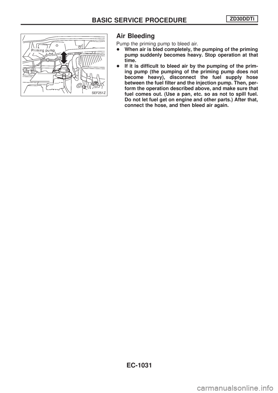
Air Bleeding
Pump the priming pump to bleed air.
+When air is bled completely, the pumping of the priming
pump suddenly becomes heavy. Stop operation at that
time.
+If it is difficult to bleed air by the pumping of the prim-
ing pump (the pumping of the priming pump does not
become heavy), disconnect the fuel supply hose
between the fuel filter and the injection pump. Then, per-
form the operation described above, and make sure that
fuel comes out. (Use a pan, etc. so as not to spill fuel.
Do not let fuel get on engine and other parts.) After that,
connect the hose, and then bleed air again.
SEF251Z
BASIC SERVICE PROCEDUREZD30DDTi
EC-1031
Page 266 of 1033
2. Change the diagnostic test mode from Mode II to Mode I by using the data link connector. (See
EC-1035.)
The emission related diagnostic information in the ECM can be erased by changing the diagnostic test mode.
+If the battery is disconnected, the emission-related diagnostic information will be lost after
approx. 24 hours.
+Erasing the emission-related diagnostic information using CONSULT-II is easier and quicker than
switching the diagnostic test mode using the data link connector.
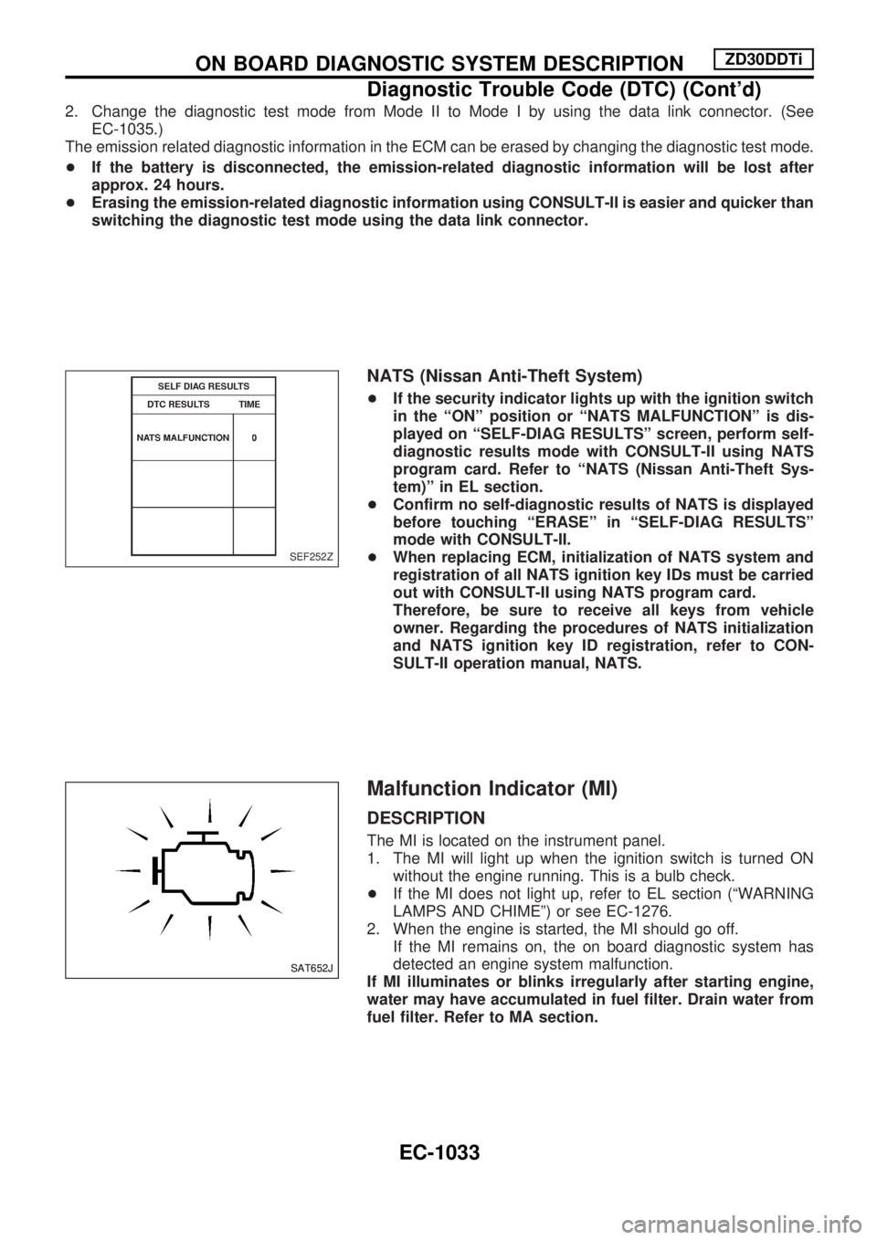
NATS (Nissan Anti-Theft System)
+If the security indicator lights up with the ignition switch
in the ªONº position or ªNATS MALFUNCTIONº is dis-
played on ªSELF-DIAG RESULTSº screen, perform self-
diagnostic results mode with CONSULT-II using NATS
program card. Refer to ªNATS (Nissan Anti-Theft Sys-
tem)º in EL section.
+Confirm no self-diagnostic results of NATS is displayed
before touching ªERASEº in ªSELF-DIAG RESULTSº
mode with CONSULT-II.
+When replacing ECM, initialization of NATS system and
registration of all NATS ignition key IDs must be carried
out with CONSULT-II using NATS program card.
Therefore, be sure to receive all keys from vehicle
owner. Regarding the procedures of NATS initialization
and NATS ignition key ID registration, refer to CON-
SULT-II operation manual, NATS.
Malfunction Indicator (MI)
DESCRIPTION
The MI is located on the instrument panel.
1. The MI will light up when the ignition switch is turned ON
without the engine running. This is a bulb check.
+If the MI does not light up, refer to EL section (ªWARNING
LAMPS AND CHIMEº) or see EC-1276.
2. When the engine is started, the MI should go off.
If the MI remains on, the on board diagnostic system has
detected an engine system malfunction.
If MI illuminates or blinks irregularly after starting engine,
water may have accumulated in fuel filter. Drain water from
fuel filter. Refer to MA section.
SEF252Z
SAT652J
ON BOARD DIAGNOSTIC SYSTEM DESCRIPTIONZD30DDTi
Diagnostic Trouble Code (DTC) (Cont'd)
EC-1033
Page 272 of 1033
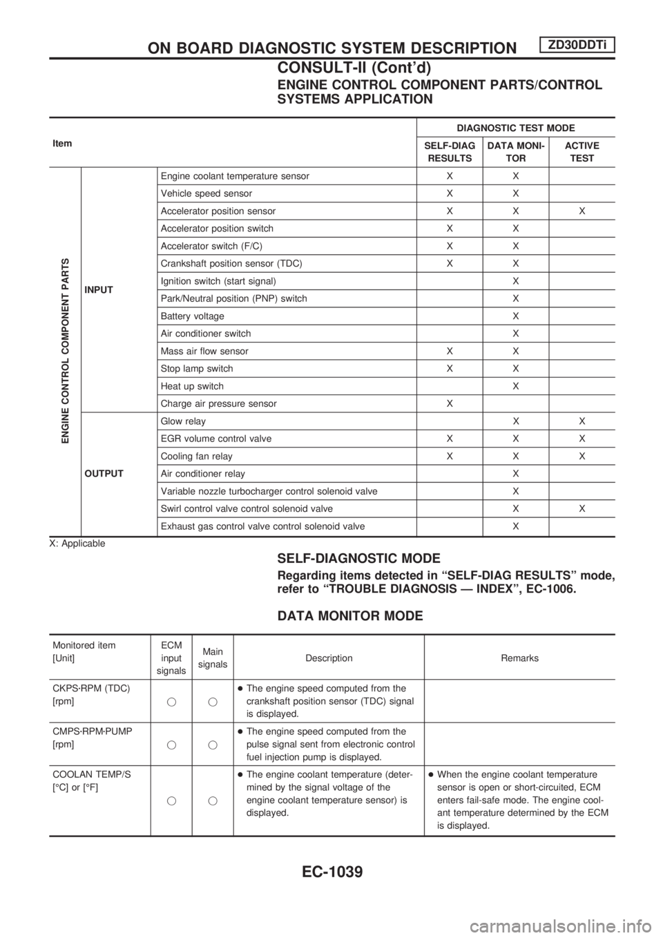
ENGINE CONTROL COMPONENT PARTS/CONTROL
SYSTEMS APPLICATION
ItemDIAGNOSTIC TEST MODE
SELF-DIAG
RESULTSDATA MONI-
TORACTIVE
TEST
ENGINE CONTROL COMPONENT PARTS
INPUTEngine coolant temperature sensor X X
Vehicle speed sensor X X
Accelerator position sensor X X X
Accelerator position switch X X
Accelerator switch (F/C) X X
Crankshaft position sensor (TDC) X X
Ignition switch (start signal) X
Park/Neutral position (PNP) switch X
Battery voltage X
Air conditioner switch X
Mass air flow sensor X X
Stop lamp switch X X
Heat up switch X
Charge air pressure sensor X
OUTPUTGlow relayXX
EGR volume control valve X X X
Cooling fan relay X X X
Air conditioner relay X
Variable nozzle turbocharger control solenoid valve X
Swirl control valve control solenoid valve X X
Exhaust gas control valve control solenoid valve X
X: Applicable
SELF-DIAGNOSTIC MODE
Regarding items detected in ªSELF-DIAG RESULTSº mode,
refer to ªTROUBLE DIAGNOSIS Ð INDEXº, EC-1006.
DATA MONITOR MODE
Monitored item
[Unit]ECM
input
signalsMain
signalsDescription Remarks
CKPSzRPM (TDC)
[rpm]jj+The engine speed computed from the
crankshaft position sensor (TDC) signal
is displayed.
CMPSzRPMzPUMP
[rpm]jj+The engine speed computed from the
pulse signal sent from electronic control
fuel injection pump is displayed.
COOLAN TEMP/S
[ÉC] or [ÉF]
jj+The engine coolant temperature (deter-
mined by the signal voltage of the
engine coolant temperature sensor) is
displayed.+When the engine coolant temperature
sensor is open or short-circuited, ECM
enters fail-safe mode. The engine cool-
ant temperature determined by the ECM
is displayed.
ON BOARD DIAGNOSTIC SYSTEM DESCRIPTIONZD30DDTi
CONSULT-II (Cont'd)
EC-1039
Page 273 of 1033
![NISSAN PATROL 2000 Electronic Repair Manual Monitored item
[Unit]ECM
input
signalsMain
signalsDescription Remarks
VHCL SPEED SE
[km/h] or [mph]jj+The vehicle speed computed from the
vehicle speed sensor signal is displayed.
FUEL TEMP SEN
[ÉC] NISSAN PATROL 2000 Electronic Repair Manual Monitored item
[Unit]ECM
input
signalsMain
signalsDescription Remarks
VHCL SPEED SE
[km/h] or [mph]jj+The vehicle speed computed from the
vehicle speed sensor signal is displayed.
FUEL TEMP SEN
[ÉC]](/manual-img/5/57367/w960_57367-272.png)
Monitored item
[Unit]ECM
input
signalsMain
signalsDescription Remarks
VHCL SPEED SE
[km/h] or [mph]jj+The vehicle speed computed from the
vehicle speed sensor signal is displayed.
FUEL TEMP SEN
[ÉC] or [ÉF]jj+The fuel temperature (sent from elec-
tronic control fuel injection pump) is dis-
played.
ACCEL POS SEN [V]
jj+The accelerator position sensor signal
voltage is displayed.
FULL ACCEL SW
[ON/OFF]jj+Indicates [ON/OFF] condition from the
accelerator position switch signal.
ACCEL SW (FC)
[OPEN/CLOSE]jj+Indicates [OPEN/CLOSE] condition from
the accelerator switch (FC) signal.
OFF ACCEL SW
[ON/OFF]jj+Indicates [ON/OFF] condition from the
accelerator position switch signal.
SPILL/V [ÉCA]
j+The control position of spill valve (sent
from electronic control fuel injection
pump) is displayed.
BATTERY VOLT [V]
jj+The power supply voltage of ECM is dis-
played.
P/N POSI SW
[ON/OFF]jj+Indicates [ON/OFF] condition from the
park/neutral position switch signal.
START SIGNAL
[ON/OFF]jj+Indicates [ON/OFF] condition from the
starter signal.+After starting the engine, [OFF] is dis-
played regardless of the starter signal.
AIR COND SIG
[ON/OFF]jj+Indicates [ON/OFF] condition of the air
conditioner switch as determined by the
air conditioner signal.
BRAKE SW [ON/OFF]
jj+Indicates [ON/OFF] condition from the
stop lamp switch signal.
IGN SW
[ON/OFF]jj+Indicates [ON/OFF] condition from igni-
tion switch signal.
WARM UP SW
[ON/OFF]j+Indicates [ON/OFF] condition from the
heat up switch signal.
MAS AIR/FL SE [V]
jj+The signal voltage of the mass air flow
sensor is displayed.+When the engine is stopped, a certain
value is indicated.
DECELER F/CUT
[ON/OFF]j+The [ON/OFF] condition from decelera-
tion fuel cut signal (sent from electronic
control fuel injection pump) is displayed.
INJ TIMG C/V [%]
j+The duty ratio of fuel injection timing
control valve (sent from electronic con-
trol fuel injection pump) is displayed.
AIR COND RLY
[ON/OFF]j+Indicates the control condition of the air
conditioner relay (determined by ECM
according to the input signals).
GLOW RLY [ON/OFF]
j+The glow relay control condition (deter-
mined by ECM according to the input
signal) is displayed.
ON BOARD DIAGNOSTIC SYSTEM DESCRIPTIONZD30DDTi
CONSULT-II (Cont'd)
EC-1040