2000 NISSAN PATROL fuse diagram
[x] Cancel search: fuse diagramPage 485 of 1033
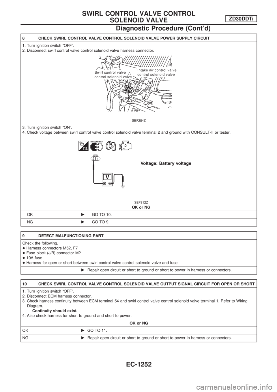
8 CHECK SWIRL CONTROL VALVE CONTROL SOLENOID VALVE POWER SUPPLY CIRCUIT
1. Turn ignition switch ªOFFº.
2. Disconnect swirl control valve control solenoid valve harness connector.
SEF284Z
3. Turn ignition switch ªONº.
4. Check voltage between swirl control valve control solenoid valve terminal 2 and ground with CONSULT-II or tester.
SEF312Z
OK or NG
OKcGO TO 10.
NGcGO TO 9.
9 DETECT MALFUNCTIONING PART
Check the following.
+Harness connectors M52, F7
+Fuse block (J/B) connector M2
+10A fuse
+Harness for open or short between swirl control valve control solenoid valve and fuse
cRepair open circuit or short to ground or short to power in harness or connectors.
10 CHECK SWIRL CONTROL VALVE CONTROL SOLENOID VALVE OUTPUT SIGNAL CIRCUIT FOR OPEN OR SHORT
1. Turn ignition switch ªOFFº.
2. Disconnect ECM harness connector.
3. Check harness continuity between ECM terminal 54 and swirl control valve control solenoid valve terminal 1. Refer to Wiring
Diagram.
Continuity should exist.
4. Also check harness for short to ground and short to power.
OK or NG
OKcGO TO 11.
NGcRepair open circuit or short to ground or short to power in harness or connectors.
SWIRL CONTROL VALVE CONTROL
SOLENOID VALVEZD30DDTi
Diagnostic Procedure (Cont'd)
EC-1252
Page 492 of 1033
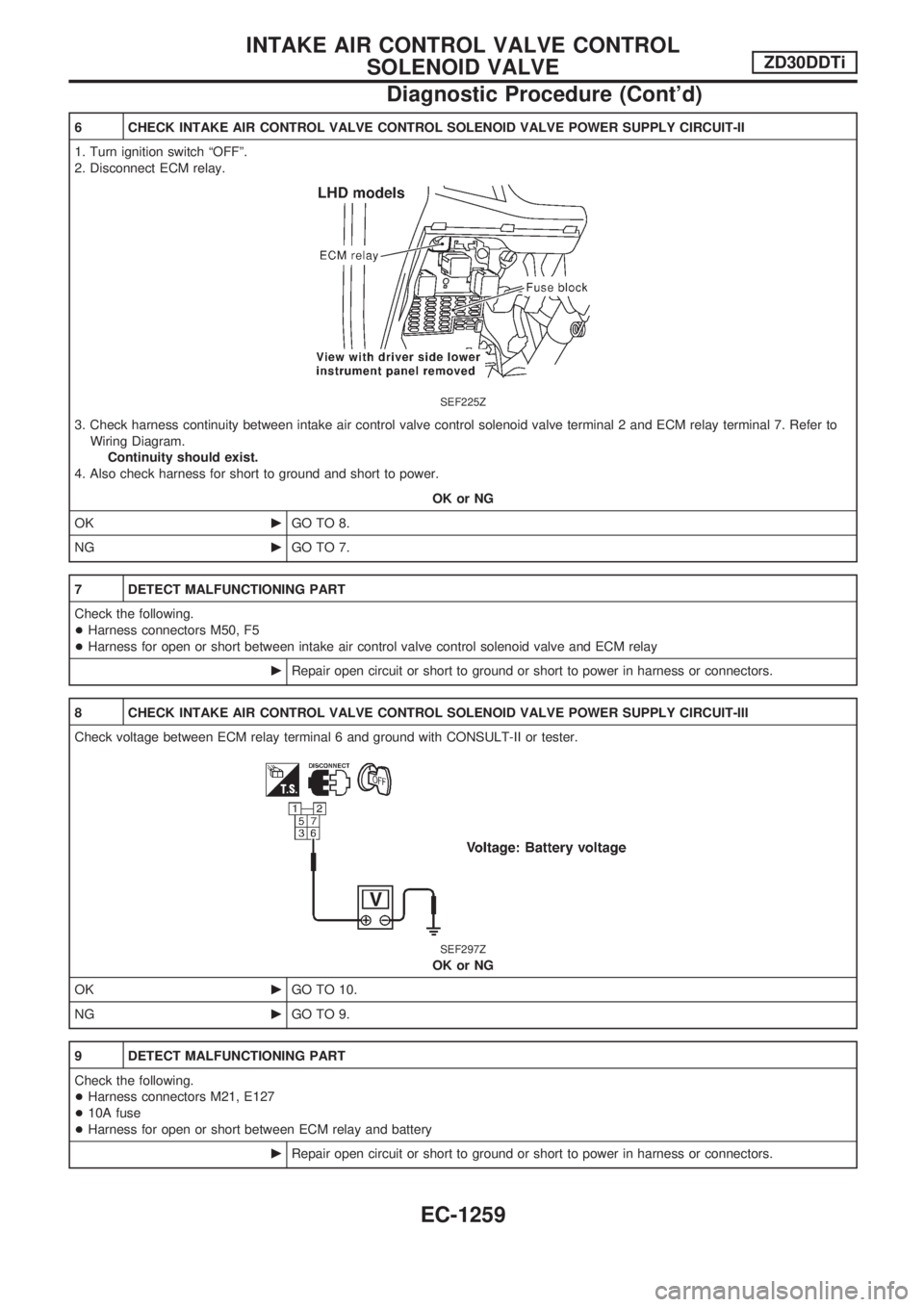
6 CHECK INTAKE AIR CONTROL VALVE CONTROL SOLENOID VALVE POWER SUPPLY CIRCUIT-II
1. Turn ignition switch ªOFFº.
2. Disconnect ECM relay.
SEF225Z
3. Check harness continuity between intake air control valve control solenoid valve terminal 2 and ECM relay terminal 7. Refer to
Wiring Diagram.
Continuity should exist.
4. Also check harness for short to ground and short to power.
OK or NG
OKcGO TO 8.
NGcGO TO 7.
7 DETECT MALFUNCTIONING PART
Check the following.
+Harness connectors M50, F5
+Harness for open or short between intake air control valve control solenoid valve and ECM relay
cRepair open circuit or short to ground or short to power in harness or connectors.
8 CHECK INTAKE AIR CONTROL VALVE CONTROL SOLENOID VALVE POWER SUPPLY CIRCUIT-III
Check voltage between ECM relay terminal 6 and ground with CONSULT-II or tester.
SEF297Z
OK or NG
OKcGO TO 10.
NGcGO TO 9.
9 DETECT MALFUNCTIONING PART
Check the following.
+Harness connectors M21, E127
+10A fuse
+Harness for open or short between ECM relay and battery
cRepair open circuit or short to ground or short to power in harness or connectors.
INTAKE AIR CONTROL VALVE CONTROL
SOLENOID VALVEZD30DDTi
Diagnostic Procedure (Cont'd)
EC-1259
Page 500 of 1033
7 DETECT MALFUNCTIONING PART
Check the following.
+Harness connectors M21, E127
+Harness connectors E69, E202
+Fuse block (J/B) connector M2
+10A fuse
+Harness for open or short between variable nozzle turbocharger control solenoid valve and fuse
cRepair open circuit or short to ground or short to power in harness or connectors.
8 CHECK VARIABLE NOZZLE TURBOCHARGER CONTROL SOLENOID VALVE OUTPUT SIGNAL CIRCUIT FOR
OPEN OR SHORT
1. Turn ignition switch ªOFFº.
2. Disconnect ECM harness connector.
3. Check harness continuity between ECM terminal 101 and variable nozzle turbocharger control solenoid valve terminal 1. Refer
to Wiring Diagram.
Continuity should exist.
4. Also check harness for short to ground and short to power.
OK or NG
OKcGO TO 10.
NGcGO TO 9.
9 DETECT MALFUNCTIONING PART
Check the following.
+Harness connectors E230, F12
+Harness for open or short between variable nozzle turbocharger control solenoid valve and ECM
cRepair open circuit or short to ground or short to power in harness or connectors.
VARIABLE NOZZLE TURBOCHARGER CONTROL
SOLENOID VALVEZD30DDTi
Diagnostic Procedure (Cont'd)
EC-1267
Page 507 of 1033
7 DETECT MALFUNCTIONING PART
Check the following.
+Harness connectors M21, E127
+Fuse block (J/B) connector M2
+10A fuse
+Harness for open or short between exhaust gas control valve control solenoid valve and fuse
cRepair open circuit or short to ground or short to power in harness or connectors.
8 CHECK EXHAUST GAS CONTROL VALVE CONTROL SOLENOID VALVE OUTPUT SIGNAL CIRCUIT FOR OPEN
OR SHORT
1. Turn ignition switch ªOFFº.
2. Disconnect ECM harness connector.
3. Check harness continuity between ECM terminal 11 and exhaust gas control valve control solenoid valve terminal 1. Refer to
Wiring Diagram.
Continuity should exist.
4. Also check harness for short to ground and short to power.
OK or NG
OKcGO TO 10.
NGcGO TO 9.
9 DETECT MALFUNCTIONING PART
Check the following.
+Harness connectors M21, E127
+Harness connectors M50, F5
+Harness for open or short between exhaust gas control valve control solenoid valve and ECM
cRepair open circuit or short to ground or short to power in harness or connectors.
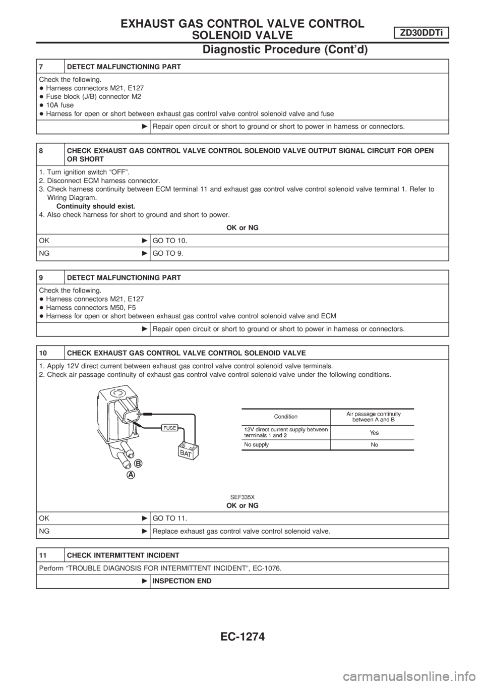
10 CHECK EXHAUST GAS CONTROL VALVE CONTROL SOLENOID VALVE
1. Apply 12V direct current between exhaust gas control valve control solenoid valve terminals.
2. Check air passage continuity of exhaust gas control valve control solenoid valve under the following conditions.
SEF335X
OK or NG
OKcGO TO 11.
NGcReplace exhaust gas control valve control solenoid valve.
11 CHECK INTERMITTENT INCIDENT
Perform ªTROUBLE DIAGNOSIS FOR INTERMITTENT INCIDENTº, EC-1076.
cINSPECTION END
EXHAUST GAS CONTROL VALVE CONTROL
SOLENOID VALVEZD30DDTi
Diagnostic Procedure (Cont'd)
EC-1274
Page 658 of 1033
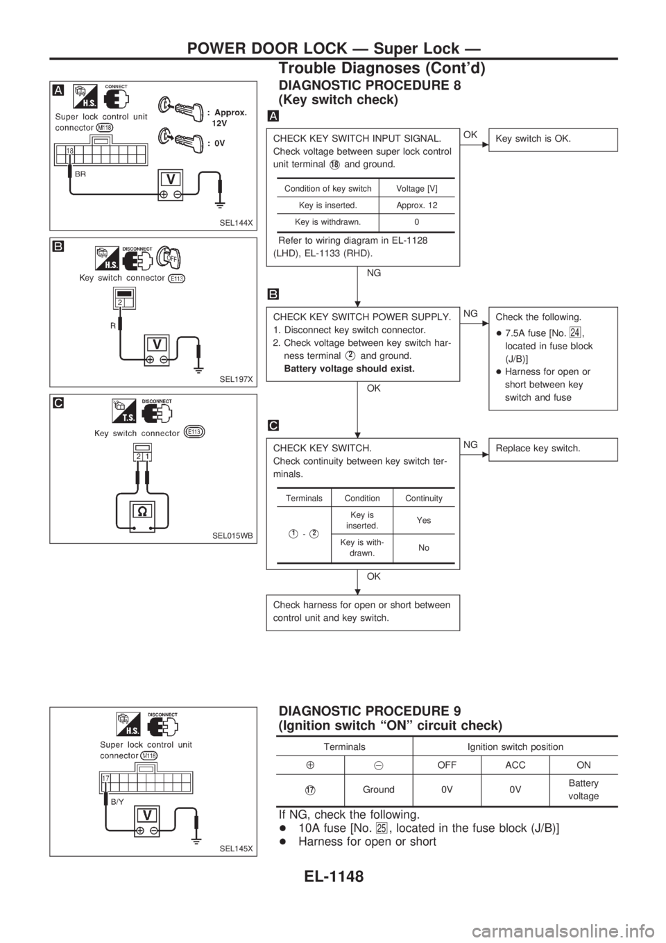
DIAGNOSTIC PROCEDURE 8
(Key switch check)
CHECK KEY SWITCH INPUT SIGNAL.
Check voltage between super lock control
unit terminal
V18and ground.
Refer to wiring diagram in EL-1128
(LHD), EL-1133 (RHD).
NG
cOK
Key switch is OK.
CHECK KEY SWITCH POWER SUPPLY.
1. Disconnect key switch connector.
2. Check voltage between key switch har-
ness terminal
V2and ground.
Battery voltage should exist.
OK
cNG
Check the following.
+7.5A fuse [No.
24,
located in fuse block
(J/B)]
+Harness for open or
short between key
switch and fuse
CHECK KEY SWITCH.
Check continuity between key switch ter-
minals.
OK
cNG
Replace key switch.
Check harness for open or short between
control unit and key switch.
Condition of key switch Voltage [V]
Key is inserted. Approx. 12
Key is withdrawn. 0
Terminals Condition Continuity
V1-V2
Key is
inserted.Yes
Key is with-
drawn.No
DIAGNOSTIC PROCEDURE 9
(Ignition switch ªONº circuit check)
Terminals Ignition switch position
Å@OFF ACC ON
V17Ground 0V 0VBattery
voltage
If NG, check the following.
+10A fuse [No.
25, located in the fuse block (J/B)]
+Harness for open or short
SEL144X
SEL197X
SEL015WB
SEL145X
.
.
.
POWER DOOR LOCK Ð Super Lock Ð
Trouble Diagnoses (Cont'd)
EL-1148
Page 684 of 1033
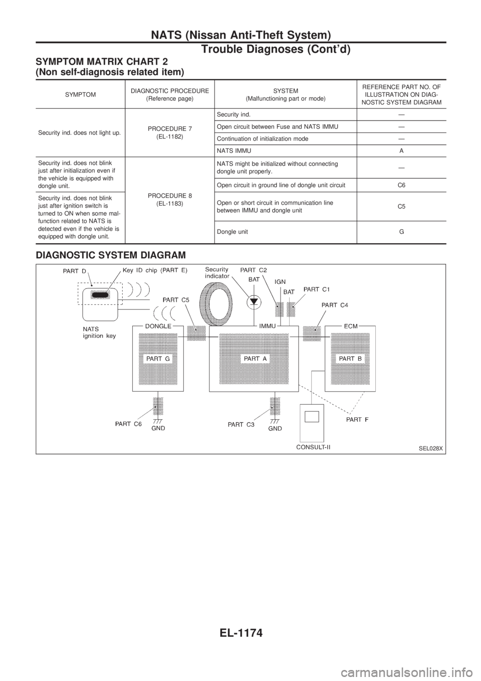
SYMPTOM MATRIX CHART 2
(Non self-diagnosis related item)
SYMPTOMDIAGNOSTIC PROCEDURE
(Reference page)SYSTEM
(Malfunctioning part or mode)REFERENCE PART NO. OF
ILLUSTRATION ON DIAG-
NOSTIC SYSTEM DIAGRAM
Security ind. does not light up.PROCEDURE 7
(EL-1182)Security ind. Ð
Open circuit between Fuse and NATS IMMU Ð
Continuation of initialization mode Ð
NATS IMMU A
Security ind. does not blink
just after initialization even if
the vehicle is equipped with
dongle unit.
PROCEDURE 8
(EL-1183)NATS might be initialized without connecting
dongle unit properly.Ð
Open circuit in ground line of dongle unit circuit C6
Security ind. does not blink
just after ignition switch is
turned to ON when some mal-
function related to NATS is
detected even if the vehicle is
equipped with dongle unit.Open or short circuit in communication line
between IMMU and dongle unitC5
Dongle unit G
DIAGNOSTIC SYSTEM DIAGRAM
SEL028X
NATS (Nissan Anti-Theft System)
Trouble Diagnoses (Cont'd)
EL-1174
Page 881 of 1033
Engine coolant temperature sensor
(ECTS) .............................................. EC-1092
Engine oil filter replacement ................. MA-1013
Engine oil replacement ......................... MA-1012
Engine removal ..................................... EM-1064
Engine serial number ............................. GI-1008
F
F/FOG - Wiring diagram ........................ EL-1052
Final drive disassembly .............. PD-1004, 1005
Fluid temperature sensor (A/T) ............. AT-1081
Fluids .................................................... MA-1008
Flywheel runout .................................... EM-1095
Fog lamp, front ...................................... EL-1052
Fog lamp, rear ....................................... EL-1053
Forward clutch ....................................... AT-1167
Front axle .............................................. FA-1002
Front final drive disassembly (4WD) .... PD-1004
Front fog lamp ....................................... EL-1052
Front passenger air bag ....................... RS-1003
Front seat .............................................. BT-1006
Front washer .......................................... EL-1098
Front wiper ............................................. EL-1098
Fuel cut control (at no load & high
engine speed) ................................... EC-1021
Fuel filter replacement .......................... MA-1017
Fuel gauge ............................................. EL-1073
Fuel injection system ............................ EC-1019
Fuel line inspection ............................... MA-1018
Fuel precautions ..................................... GI-1002
Fuse block ............................................. EL-1229
Fuse ....................................................... EL-1230
Fusible link ............................................. EL-1230
G
GLOW - Wiring diagram ....................... EC-1221
Gauges .................................................. EL-1073
Glow plug .............................................. EC-1221
Glow relay ............................................. EC-1221
Grease ........................................ MA-1008, 1016
Ground distribution ................................ EL-1013
H
HEAT UP - Wiring diagram .................. EC-1242
HEATER - Wiring diagram .................... HA-1005
HLC - Wiring diagram ............................ EL-1099
HORN - Wiring diagram ........................ EL-1100
Harness layout ....................................... EL-1191
Hazard warning lamp ............................ EL-1058
Headlamp washer .................................. EL-1099
Headlamp wiper ..................................... EL-1099
Headlamp .............................................. EL-1044
Heat up switch ...................................... EC-1241
High clutch ............................................. AT-1165Horn ....................................................... EL-1100
How to erase DTC for OBD system ..... EC-1032
I
ILL - Wiring diagram .............................. EL-1061
Identification plate .................................. GI-1008
Idle speed ............................................. EC-1049
Illumination ............................................. EL-1060
Injection nozzle ..................................... EC-1023
Intake manifold ..................................... EM-1012
Interior lamp ........................................... EL-1067
Interior ................................................... BT-1004
J
Junction box (J/B) .................................. EL-1229
L
License lamp ......................................... EL-1046
Lifting points ........................................... GI-1009
Line pressure solenoid valve ................ AT-1086
Line pressure test (A/T) ........................ AT-1044
Liquid gasket application ...................... EM-1003
Location of electrical units ..................... EL-1185
Low and reverse brake ......................... AT-1171
Lubricants ............................................. MA-1008
Luggage room lamp .............................. EL-1067
M
MAFS - Wiring diagram ........................ EC-1086
MAIN - Wiring diagram ......................... EC-1077
MAJOR OVERHALL .............................. AT-1129
METER - Wiring diagram ...................... EL-1073
Maintenance (engine) ........................... MA-1011
Malfunction indicator lamp (MIL) .......... EC-1033
Manifold tightening torque (intake &
exhaust) ............................................ MA-1011
Mass air flow sensor (MAFS) ............... EC-1086
Meter ...................................................... EL-1073
Mirror, door ............................................ BT-1007
Mirror, outside ....................................... BT-1007
Model variation ....................................... GI-1005
N
NATS (Nissan Anti-theft System) .......... EL-1163
NATS - Wiring diagram ......................... EL-1166
NVH troubleshooting (EM) ................... EM-1008
ALPHABETICAL INDEX
IDX-1003