2000 NISSAN PATROL air filter
[x] Cancel search: air filterPage 153 of 1033
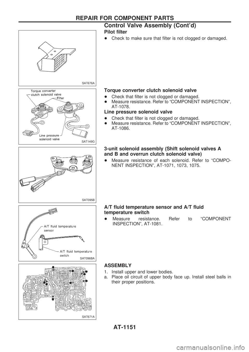
Pilot filter
+Check to make sure that filter is not clogged or damaged.
Torque converter clutch solenoid valve
+Check that filter is not clogged or damaged.
+Measure resistance. Refer to ªCOMPONENT INSPECTIONº,
AT-1078.
Line pressure solenoid valve
+Check that filter is not clogged or damaged.
+Measure resistance. Refer to ªCOMPONENT INSPECTIONº,
AT-1086.
3-unit solenoid assembly (Shift solenoid valves A
and B and overrun clutch solenoid valve)
+Measure resistance of each solenoid. Refer to ªCOMPO-
NENT INSPECTIONº, AT-1071, 1073, 1075.
A/T fluid temperature sensor and A/T fluid
temperature switch
+Measure resistance. Refer to ªCOMPONENT
INSPECTIONº, AT-1081.
ASSEMBLY
1. Install upper and lower bodies.
a. Place oil circuit of upper body face up. Install steel balls in
their proper positions.
SAT676A
SAT149G
SAT095B
SAT096BA
SAT671A
REPAIR FOR COMPONENT PARTS
Control Valve Assembly (Cont'd)
AT-1151
Page 154 of 1033
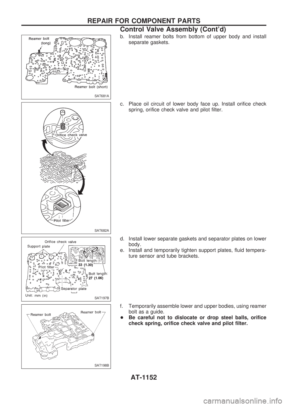
b. Install reamer bolts from bottom of upper body and install
separate gaskets.
c. Place oil circuit of lower body face up. Install orifice check
spring, orifice check valve and pilot filter.
d. Install lower separate gaskets and separator plates on lower
body.
e. Install and temporarily tighten support plates, fluid tempera-
ture sensor and tube brackets.
f. Temporarily assemble lower and upper bodies, using reamer
bolt as a guide.
+Be careful not to dislocate or drop steel balls, orifice
check spring, orifice check valve and pilot filter.
SAT681A
SAT682A
SAT197B
SAT198B
REPAIR FOR COMPONENT PARTS
Control Valve Assembly (Cont'd)
AT-1152
Page 242 of 1033
tion due to receiving external noise, degraded operation
of ICs, etc.
+Keep ECM parts and harnesses dry.
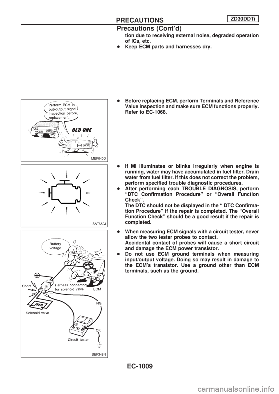
+Before replacing ECM, perform Terminals and Reference
Value inspection and make sure ECM functions properly.
Refer to EC-1068.
+If MI illuminates or blinks irregularly when engine is
running, water may have accumulated in fuel filter. Drain
water from fuel filter. If this does not correct the problem,
perform specified trouble diagnostic procedures.
+After performing each TROUBLE DIAGNOSIS, perform
ªDTC Confirmation Procedureº or ªOverall Function
Checkº.
The DTC should not be displayed in the ª DTC Confirma-
tion Procedureº if the repair is completed. The ªOverall
Function Checkº should be a good result if the repair is
completed.
+When measuring ECM signals with a circuit tester, never
allow the two tester probes to contact.
Accidental contact of probes will cause a short circuit
and damage the ECM power transistor.
+Do not use ECM ground terminals when measuring
input/output voltage. Doing so may result in damage to
the ECM's transistor. Use a ground other than ECM
terminals, such as the ground.
MEF040D
SAT652J
SEF348N
PRECAUTIONSZD30DDTi
Precautions (Cont'd)
EC-1009
Page 264 of 1033
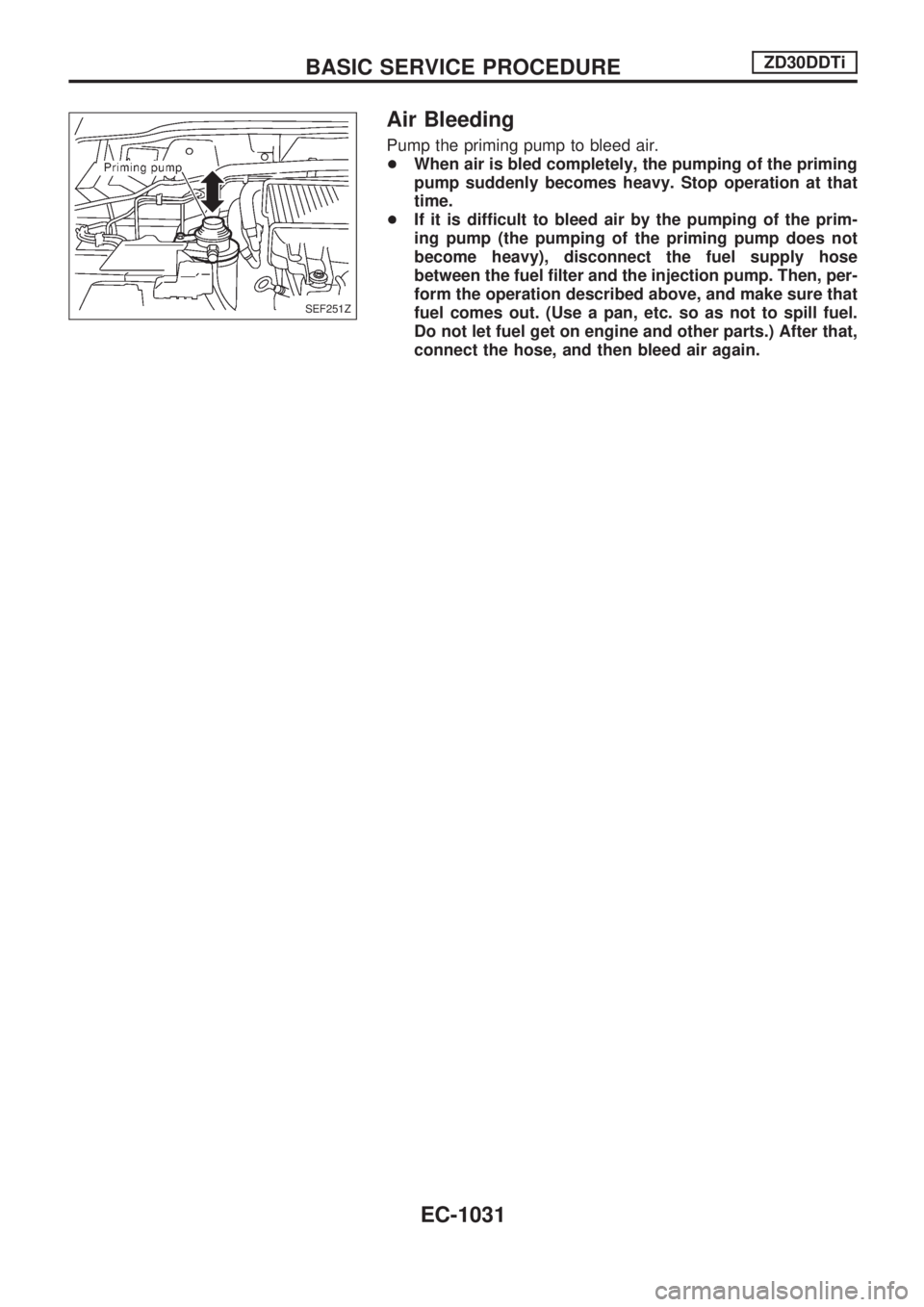
Air Bleeding
Pump the priming pump to bleed air.
+When air is bled completely, the pumping of the priming
pump suddenly becomes heavy. Stop operation at that
time.
+If it is difficult to bleed air by the pumping of the prim-
ing pump (the pumping of the priming pump does not
become heavy), disconnect the fuel supply hose
between the fuel filter and the injection pump. Then, per-
form the operation described above, and make sure that
fuel comes out. (Use a pan, etc. so as not to spill fuel.
Do not let fuel get on engine and other parts.) After that,
connect the hose, and then bleed air again.
SEF251Z
BASIC SERVICE PROCEDUREZD30DDTi
EC-1031
Page 282 of 1033
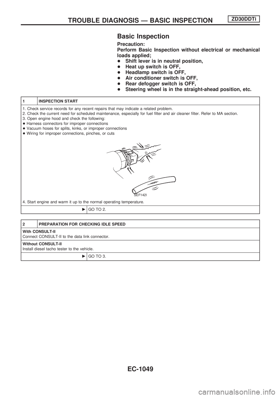
Basic Inspection
Precaution:
Perform Basic Inspection without electrical or mechanical
loads applied;
+Shift lever is in neutral position,
+Heat up switch is OFF,
+Headlamp switch is OFF,
+Air conditioner switch is OFF,
+Rear defogger switch is OFF,
+Steering wheel is in the straight-ahead position, etc.
1 INSPECTION START
1. Check service records for any recent repairs that may indicate a related problem.
2. Check the current need for scheduled maintenance, especially for fuel filter and air cleaner filter. Refer to MA section.
3. Open engine hood and check the following:
+Harness connectors for improper connections
+Vacuum hoses for splits, kinks, or improper connections
+Wiring for improper connections, pinches, or cuts
SEF142I
4. Start engine and warm it up to the normal operating temperature.
cGO TO 2.
2 PREPARATION FOR CHECKING IDLE SPEED
With CONSULT-II
Connect CONSULT-II to the data link connector.
Without CONSULT-II
Install diesel tacho tester to the vehicle.
cGO TO 3.
TROUBLE DIAGNOSIS Ð BASIC INSPECTIONZD30DDTi
EC-1049
Page 286 of 1033
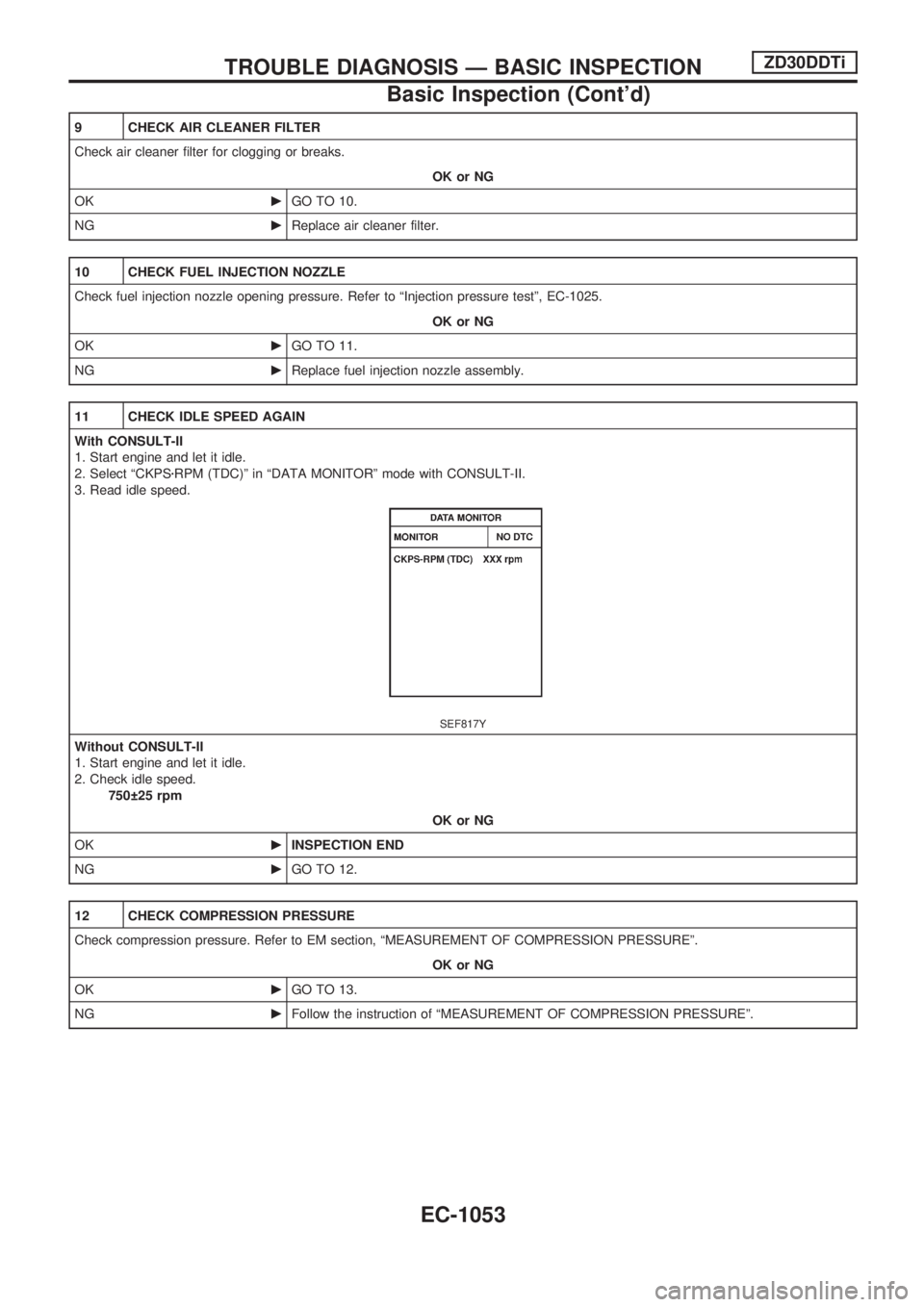
9 CHECK AIR CLEANER FILTER
Check air cleaner filter for clogging or breaks.
OK or NG
OKcGO TO 10.
NGcReplace air cleaner filter.
10 CHECK FUEL INJECTION NOZZLE
Check fuel injection nozzle opening pressure. Refer to ªInjection pressure testº, EC-1025.
OK or NG
OKcGO TO 11.
NGcReplace fuel injection nozzle assembly.
11 CHECK IDLE SPEED AGAIN
With CONSULT-II
1. Start engine and let it idle.
2. Select ªCKPSzRPM (TDC)º in ªDATA MONITORº mode with CONSULT-II.
3. Read idle speed.
SEF817Y
Without CONSULT-II
1. Start engine and let it idle.
2. Check idle speed.
750 25 rpm
OK or NG
OKcINSPECTION END
NGcGO TO 12.
12 CHECK COMPRESSION PRESSURE
Check compression pressure. Refer to EM section, ªMEASUREMENT OF COMPRESSION PRESSUREº.
OK or NG
OKcGO TO 13.
NGcFollow the instruction of ªMEASUREMENT OF COMPRESSION PRESSUREº.
TROUBLE DIAGNOSIS Ð BASIC INSPECTIONZD30DDTi
Basic Inspection (Cont'd)
EC-1053
Page 880 of 1033
A
A/T - Wiring diagram ............................. AT-1009
A/T control ............................................. EC-1148
A/T fluid temperature sensor ................. AT-1081
A/T mode switch .................................... AT-1095
A/T self-diagnoses ................................. AT-1028
A/T shift lock system - Wiring
diagram .............................................. AT-1117
A/T shift lock system ............................. AT-1116
A/T trouble diagnoses ........................... AT-1036
APS - Wiring diagram ........................... EC-1125
ASCD (automatic speed control
device) ............................................... EL-1110
ASCD - Wiring diagram ......................... EL-1111
AT/C - Wiring diagram .......................... EC-1150
Accelerator control system .................... FE-1007
Accelerator position sensor .................. EC-1125
Air bag disposal .................................... RS-1015
Air bag precautions ................................ GI-1002
Air bag ................................................... RS-1003
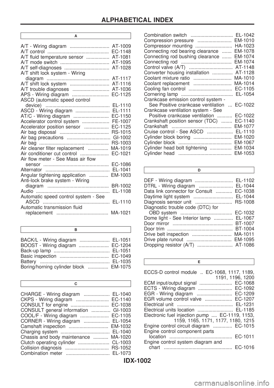
Air cleaner filter replacement ............... MA-1019
Air conditioner cut control ..................... EC-1021
Air flow meter - See Mass air flow
sensor ................................................ EC-1086
Alternator ............................................... EL-1041
Angular tightening application .............. EM-1003
Anti-lock brake system - Wiring
diagram ............................................. BR-1002
Audio ...................................................... EL-1108
Automatic speed control system - See
ASCD ................................................. EL-1110
Automatic transmission fluid
replacement ...................................... MA-1021
B
BACK/L - Wiring diagram ...................... EL-1051
BOOST - Wiring diagram ...................... EC-1204
Back-up lamp ......................................... EL-1051
Basic inspection .................................... EC-1049
Battery ................................................... EL-1035
Boring/horning cylinder block ............... EM-1075
C
CHARGE - Wiring diagram ................... EL-1040
CKPS - Wiring diagram ........................ EC-1140
CONSULT for engine ............................ EC-1038
CONSULT general information .............. GI-1003
COOL/F - Wiring diagram ..................... EC-1105
CORNER - Wiring diagram ................... EL-1054
Camshaft inspection ............................. EM-1032
Charging system .................................... EL-1040
Chassis and body maintenance ........... MA-1020
Clutch operating cylinder ....................... CL-1003
Collision diagnosis ................................ RS-1052
Combination meter ................................ EL-1073Combination switch ............................... EL-1042
Compression pressure ......................... EM-1010
Compressor mounting ........................... HA-1023
Connecting rod bearing clearance ....... EM-1078
Connecting rod bushing clearance ....... EM-1074
Connecting rod ..................................... EM-1074
Control valve (A/T) ................................ AT-1148
Converter housing installation ............... AT-1128
Coolant mixture ratio ............................ MA-1010
Coolant replacement ............................ MA-1014
Cooling fan control ................................ EC-1105
Cornering lamp ...................................... EL-1054
Crankcase emission control system -
See Positive crankcase ventilation ... EC-1022
Crankcase ventilation system - See
Positive crankcase ventilation ........... EC-1022
Crankshaft position sensor (TDC) ........ EC-1140
Crankshaft ............................................ EM-1077
Cruise control - See ASCD ................... EL-1110
Cylinder block boring ............................ EM-1020
Cylinder block ....................................... EM-1067
Cylinder head bolt tightening ................ EM-1034
Cylinder head ....................................... EM-1053
D
DEF - Wiring diagram ............................ EL-1102
DTRL - Wiring diagram ......................... EL-1044
Data link connector for Consult ............ EC-1038
Daytime light system ............................. EL-1044
Diagnosis sensor unit ........................... RS-1008
Diagnostic trouble code (DTC) for
OBD system ...................................... EC-1032
Dome light - See Interior lamp .............. EL-1067
Door mirror ............................................ BT-1007
Door trim ................................................ BT-1004
Drive belt inspection ............................. MA-1011
Drive plate runout ................................. EM-1095
Dropping resistor (A/T) .......................... AT-1086
E
ECCS-D control module .. EC-1068, 1117, 1189,
1191, 1196, 1200
ECM input/output signal ........................ EC-1068
ECTS - Wiring diagram ......................... EC-1092
EGR - Wiring diagram .......................... EC-1209
EGR volume control valve .................... EC-1207
Electrical unit ......................................... EL-1231
Electrical units location .......................... EL-1185
Electronic fuel injection pump .... EC-1119, 1153,
1159, 1165, 1171, 1177, 1180, 1215
Engine control circuit diagram .............. EC-1015
Engine control component parts
location .............................................. EC-1011
Engine control system diagram and
chart .................................................. EC-1016
ALPHABETICAL INDEX
IDX-1002
Page 881 of 1033
Engine coolant temperature sensor
(ECTS) .............................................. EC-1092
Engine oil filter replacement ................. MA-1013
Engine oil replacement ......................... MA-1012
Engine removal ..................................... EM-1064
Engine serial number ............................. GI-1008
F
F/FOG - Wiring diagram ........................ EL-1052
Final drive disassembly .............. PD-1004, 1005
Fluid temperature sensor (A/T) ............. AT-1081
Fluids .................................................... MA-1008
Flywheel runout .................................... EM-1095
Fog lamp, front ...................................... EL-1052
Fog lamp, rear ....................................... EL-1053
Forward clutch ....................................... AT-1167
Front axle .............................................. FA-1002
Front final drive disassembly (4WD) .... PD-1004
Front fog lamp ....................................... EL-1052
Front passenger air bag ....................... RS-1003
Front seat .............................................. BT-1006
Front washer .......................................... EL-1098
Front wiper ............................................. EL-1098
Fuel cut control (at no load & high
engine speed) ................................... EC-1021
Fuel filter replacement .......................... MA-1017
Fuel gauge ............................................. EL-1073
Fuel injection system ............................ EC-1019
Fuel line inspection ............................... MA-1018
Fuel precautions ..................................... GI-1002
Fuse block ............................................. EL-1229
Fuse ....................................................... EL-1230
Fusible link ............................................. EL-1230
G
GLOW - Wiring diagram ....................... EC-1221
Gauges .................................................. EL-1073
Glow plug .............................................. EC-1221
Glow relay ............................................. EC-1221
Grease ........................................ MA-1008, 1016
Ground distribution ................................ EL-1013
H
HEAT UP - Wiring diagram .................. EC-1242
HEATER - Wiring diagram .................... HA-1005
HLC - Wiring diagram ............................ EL-1099
HORN - Wiring diagram ........................ EL-1100
Harness layout ....................................... EL-1191
Hazard warning lamp ............................ EL-1058
Headlamp washer .................................. EL-1099
Headlamp wiper ..................................... EL-1099
Headlamp .............................................. EL-1044
Heat up switch ...................................... EC-1241
High clutch ............................................. AT-1165Horn ....................................................... EL-1100
How to erase DTC for OBD system ..... EC-1032
I
ILL - Wiring diagram .............................. EL-1061
Identification plate .................................. GI-1008
Idle speed ............................................. EC-1049
Illumination ............................................. EL-1060
Injection nozzle ..................................... EC-1023
Intake manifold ..................................... EM-1012
Interior lamp ........................................... EL-1067
Interior ................................................... BT-1004
J
Junction box (J/B) .................................. EL-1229
L
License lamp ......................................... EL-1046
Lifting points ........................................... GI-1009
Line pressure solenoid valve ................ AT-1086
Line pressure test (A/T) ........................ AT-1044
Liquid gasket application ...................... EM-1003
Location of electrical units ..................... EL-1185
Low and reverse brake ......................... AT-1171
Lubricants ............................................. MA-1008
Luggage room lamp .............................. EL-1067
M
MAFS - Wiring diagram ........................ EC-1086
MAIN - Wiring diagram ......................... EC-1077
MAJOR OVERHALL .............................. AT-1129
METER - Wiring diagram ...................... EL-1073
Maintenance (engine) ........................... MA-1011
Malfunction indicator lamp (MIL) .......... EC-1033
Manifold tightening torque (intake &
exhaust) ............................................ MA-1011
Mass air flow sensor (MAFS) ............... EC-1086
Meter ...................................................... EL-1073
Mirror, door ............................................ BT-1007
Mirror, outside ....................................... BT-1007
Model variation ....................................... GI-1005
N
NATS (Nissan Anti-theft System) .......... EL-1163
NATS - Wiring diagram ......................... EL-1166
NVH troubleshooting (EM) ................... EM-1008
ALPHABETICAL INDEX
IDX-1003