Page 1277 of 1839

ABS <4WD> -Troubleshooting35B-14
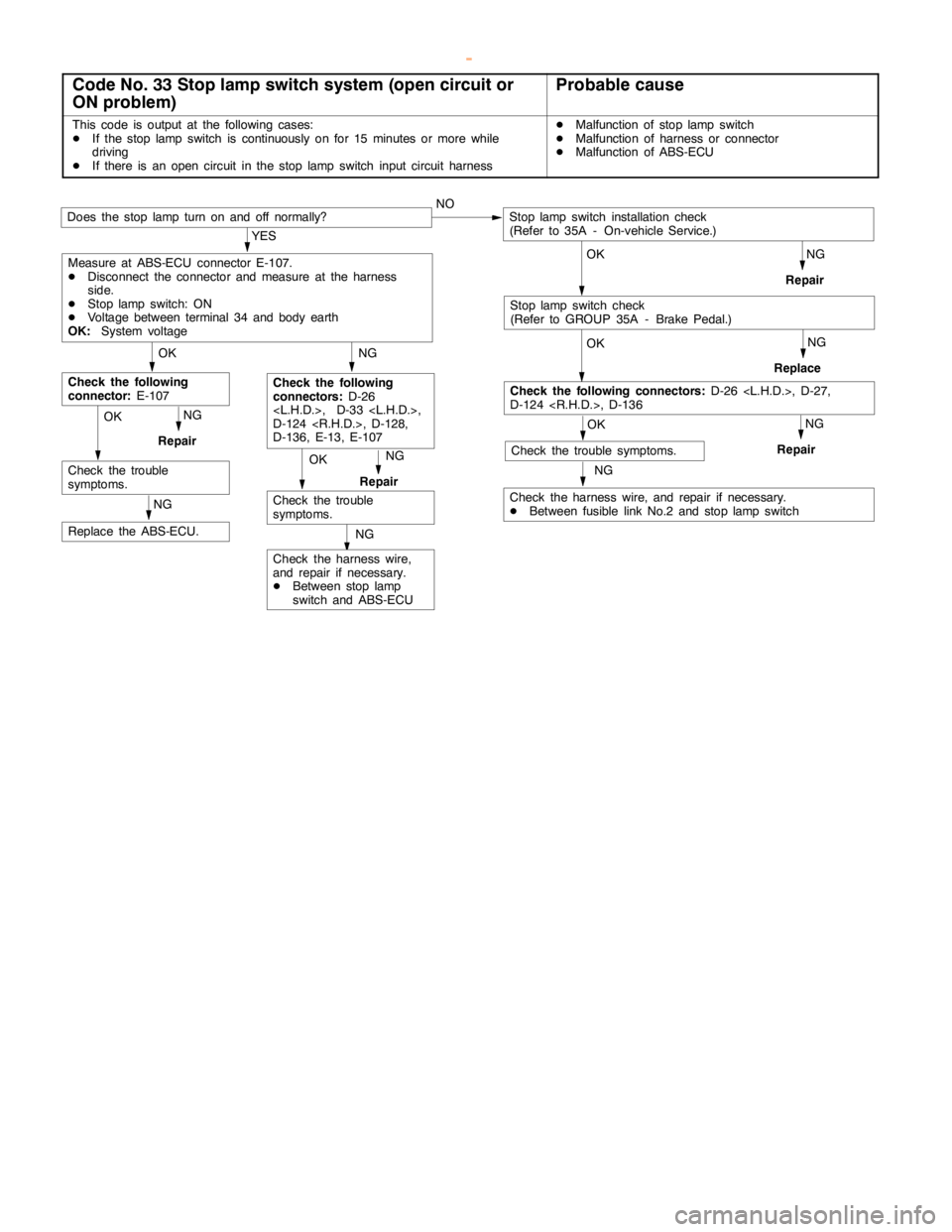
Code No. 33 Stop lamp switch system (open circuit or
ON problem)Probable cause
This code is output at the following cases:
DIf the stoplampswitch is continuously on for 15 minutes or more while
driving
DIf there is an opencircuit in the stoplampswitch input circuit harnessDMalfunction of stoplampswitch
DMalfunction of harness or connector
DMalfunction of ABS-ECU
OK
NG
Check the harness wire,
and repair if necessary.
DBetween stoplamp
switch and ABS-ECU
NG
Replace the ABS-ECU.
NG
Repair
Check the trouble
symptoms.NG
Repair
OK
Check the trouble
symptoms.
NG
Check the following
connectors:D-26
, D-33 ,
D-124 , D-128,
D-136, E-13, E-107
OK
Check the following
connector:E-107
NG
Check the harness wire, and repair if necessary.
DBetween fusible link No.2 and stoplampswitch
OK
OK
Check the following connectors:D-26 , D-27,
D-124 , D-136
OK
Does the stoplampturn on and off normally?NO
NG
Repair
NG
Replace
NG
Repair
YES
Measure at ABS-ECU connector E-107.
DDisconnect the connector and measure at the harness
side.
DStoplampswitch: ON
DVoltage between terminal 34 and body earth
OK:System voltage
Stoplampswitch installation check
(Refer to 35A - On-vehicle Service.)
Check the trouble symptoms.
Stoplampswitch check
(Refer to GROUP 35A - Brake Pedal.)
OK
www.WorkshopManuals.co.uk
Purchased from www.WorkshopManuals.co.uk
Page 1281 of 1839

ABS <4WD> -Troubleshooting35B-18
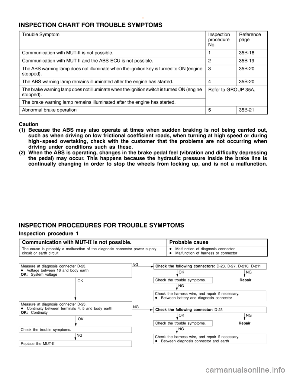
INSPECTION CHART FOR TROUBLE SYMPTOMS
Trouble SymptomInspection
procedure
No.Reference
page
Communication with MUT-II is not possible.135B-18
Communication with MUT-II and the ABS-ECU is not possible.235B-19
The ABS warning lamp does not illuminate when the ignition key is turned to ON (engine
stopped).335B-20
The ABS warning lamp remains illuminated after the engine has started.435B-20
The brake warning lamp does not illuminate when the ignition switch is turned ON (engine
stopped).Refer to GROUP 35A.
The brake warning lamp remains illuminated after the engine has started.
Abnormal brake operation535B-21
Caution
(1) Because the ABS may also operate at times when sudden braking is not being carried out,
such as when driving on low frictional coefficient roads, when turning at high speed or during
high - speed overtaking, check with the customer that the problems are not occurring when
driving under conditions such as these.
(2) When the ABS is operating, changes in the brake pedal feel (vibration and difficulty depressing
the pedal) may occur. This happens because the hydraulic pressure inside the brake line is
continually changing in order to stop the wheels from locking up, and is not a malfunction.
INSPECTION PROCEDURES FOR TROUBLE SYMPTOMS
Inspection procedure 1
Communication with MUT-II
is not possible.
Probable cause
The cause is probably a malfunction of the diagnosis connector power supply
circuit or earth circuit.DMalfunction of diagnosis connector
DMalfunction of harness or connector
NGCheck the following connectors:D-23, D-27, D-210, D-211
NG
Repair
OK
Check the trouble symptoms.
NG
Check the harness wire, and repair if necessary.
DBetween battery and diagnosis connector
OK
NG
NG
Repair
OK
Check the trouble symptoms.
NG
Check the harness wire, and repair if necessary.
DBetween diagnosis connector and earth
OK
NG
Replace the MUT-
II.
Measure at diagnosis connecter D-23.
DVoltage between 16 and body earth
OK:System voltage
Check the following connector:D-23
Measure at diagnosis connecter D-23.
DContinuity between terminals 4, 5 and body earth
OK:Continuity
Check the trouble symptoms.
www.WorkshopManuals.co.uk
Purchased from www.WorkshopManuals.co.uk
Page 1284 of 1839

ABS <4WD> -Troubleshooting35B-21
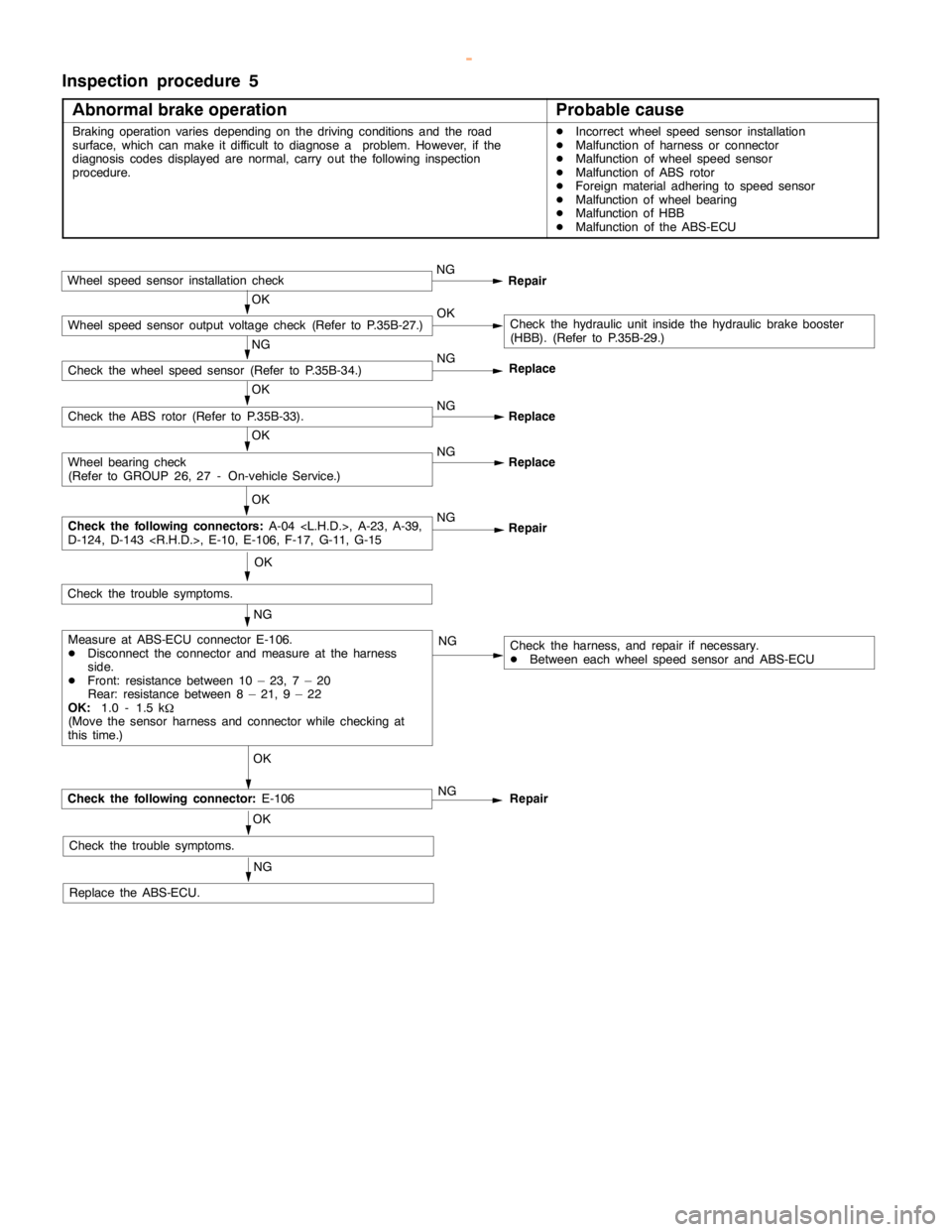
Inspection procedure 5
Abnormal brake operation
Probable cause
Braking operation variesdepending on the driving conditions and the road
surface, which can make it difficult to diagnose a problem. However, if the
diagnosis codes displayed are normal, carry out the following inspection
procedure.DIncorrect wheel speed sensor installation
DMalfunction of harness or connector
DMalfunction of wheel speed sensor
DMalfunction of ABS rotor
DForeign material adhering to speed sensor
DMalfunction of wheel bearing
DMalfunction of HBB
DMalfunction of the ABS-ECU
Wheel speed sensor installation checkNG
Repair
OKCheck the hydraulic unit inside the hydraulic brake booster
(HBB). (Refer to P.35B-29.)
NG
Check the wheel speed sensor (Refer to P.35B-34.)NG
OK
Check the ABS rotor (Refer to P.35B-33).NG
Replace
OK
NG
Replace
OK
NG
Repair
OK
NG
NG
OK
Check the following connector:E-106
OK
Check the trouble symptoms.
NG
Replace the ABS-ECU.NG
Repair
Check the harness, and repair if necessary.
DBetween each wheel speed sensor and ABS-ECU ReplaceMeasure at ABS-ECU connector E-106.
DDisconnect the connector and measure at the harness
side.
DFront: resistance between 10 – 23, 7 – 20
Rear: resistance between 8 – 21, 9 – 22
OK:1.0 - 1.5 k
W
(Move the sensor harness and connector while checking at
this time.)
Check the following connectors:A-04 , A-23, A-39,
D-124, D-143 , E-10, E-106, F-17, G-11, G-15
Wheel bearing check
(Refer to GROUP 26, 27 - On-vehicle Service.)
Check the trouble symptoms.
Wheel speed sensor output voltage check (Refer to P.35B-27.)OK
www.WorkshopManuals.co.uk
Purchased from www.WorkshopManuals.co.uk
Page 1285 of 1839

ABS <4WD> -Troubleshooting35B-22
DATA LIST REFERENCE TABLE
The following ECU input data items can be read using the MUT-II
.
(1) When system is normal
Item
No.Check itemInspection conditionsNormal condi-
tion
11Front - right wheel
speedWhen vehicle is being drivenSpeedometer
display and
12Front - left wheel
speedMUT-IIdisplay
are identical.
13Rear - right wheel
speed
14Rear - left wheel
speed
16System voltageIgnition switch: ON6.5 - 22.3 V
26Center differential
lock switchIgnition switch: ONTransfer selector lever position:
2H, 4HOFF
Transfer selector lever position:
4HLc, 4LLcON
27Rear differential lock
switchIgnition switch: ONOFF
32G sensorD
Ignition switch: ON
D
When vehicle is stationary (level)2.4 - 2.6 V
When vehicle is being driven1.0 - 4.0 V
33Stop lampIgnition switch: ONWhen brake pedal is depressedON
SwitchWhen brake pedal is releasedOFF
(2) When system is interrupted by the ECU
When the diagnosis function has caused the operation of the ABS-ECU to be stopped, the
MUT-II
display data may be different from the actual condition.
ACTUATOR TEST TABLE
The following actuators can be force-driven using the MUT-II
.
NOTE
(1) Actuator tests cannot be carried out when the operation of the ABS-ECU has been stopped by
the fail-safe function.
(2) Actuator tests can only be carried out while the vehicle is stopped.
ACTUATOR TEST SPECIFICATIONS
Item No.Check itemDrive Contents
01FR wheel solenoid valveHBB select solenoid valves and control solenoid valves for the
02FL wheel solenoid valverespective channel
03RR wheel solenoid valve
04RL wheel solenoid valve
27Air bleeding (1)HBB select solenoid valves and control solenoid valve OUT (FR, FL)
28Air bleeding (2)HBB control solenoid valve OUT (RR, RL)
www.WorkshopManuals.co.uk
Purchased from www.WorkshopManuals.co.uk
Page 1288 of 1839

ABS <4WD> -Troubleshooting35B-25
Termi-
nal
No.Normal condition Inspection conditions Check item
37ABS valve relay outputIgnition
switch: ONWhen system abnormality is
detected and relay is offSystem voltage
When relay is on approx. 1
second after engine starts2 V or less
39Brake warning lamp outputIgnitionWhen lamp is switched off2 V or less
switch: ONWhen lamp is illuminatedSystem voltage
40Control solenoid valve OUT (RL)Ignition switch: ONSystem voltage
41Control solenoid valve OUT(FR)Ignition switch: ONSystem voltage
46Center differential lock switch
input Ignition
switch: ONTransfer selector lever position:
2H, 4HSystem voltage
Transfer selector lever position:
4HLc, 4LLc2 V or less
4WD detection switch input
Ignition
switch: ONTransfer selector lever position:
2HSystem voltage
Transfer selector lever position:
4H2 V or less
47Diagnosis select inputWhen the MUT-IIis connected1 V or less
When the MUT-IIis not connectedApprox. 12 V
48Valve relay monitorIgnition switch: ONSystem voltage
50ABS warning lamp outputIgnitionWhen lamp is switched offSystem voltage
switch: ONWhen lamp is illuminated2 V or less
51Control solenoid valve IN (RL)Ignition switch: ONSystem voltage
52Control solenoid valve IN (FR)Ignition switch: ONSystem voltage
www.WorkshopManuals.co.uk
Purchased from www.WorkshopManuals.co.uk
Page 1300 of 1839
PARKING BRAKES
Click on the applicable bookmark to selected the required model year.
www.WorkshopManuals.co.uk
Purchased from www.WorkshopManuals.co.uk
Page 1301 of 1839
36-1
PARKING BRAKES
CONTENTS
GENERAL INFORMATION 2..................
SERVICE SPECIFICATIONS 2.................
LUBRICANTS 2..............................
SEALANT 3..................................
ON-VEHICLE SERVICE 3.....................
Parking Brake Lever Stroke Check and
Adjustment 3..................................Parking Brake Switch Check 4..................
Lining Running-In 4............................
PARKING BRAKE LEVER 5..................
PARKING BRAKE CABLE 6..................
PARKING BRAKE DRUM 7...................
www.WorkshopManuals.co.uk
Purchased from www.WorkshopManuals.co.uk
Page 1305 of 1839
P
A RKIN G BRAKE LE VER
R EM OVA L AND IN STA LLA TIO N B
A 4
2
3 1
6
7
84
.9
±1
.0
N×m
7 B