2000 MITSUBISHI MONTERO wheel
[x] Cancel search: wheelPage 590 of 1839
13E-1
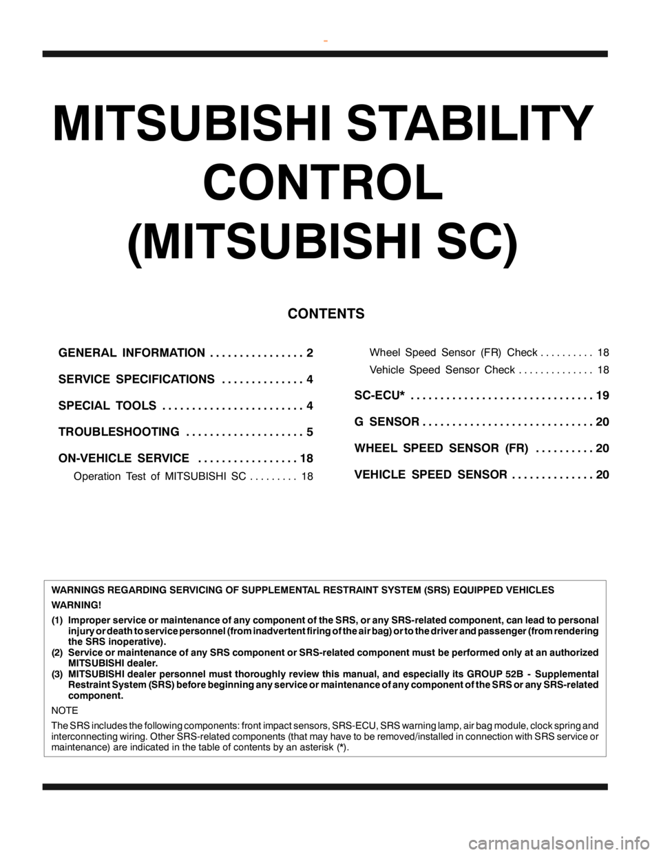
MITSUBISHI STABILITY
CONTROL
(MITSUBISHI SC)
CONTENTS
GENERAL INFORMATION 2................
SERVICE SPECIFICATIONS 4..............
SPECIAL TOOLS 4........................
TROUBLESHOOTING 5....................
ON-VEHICLE SERVICE 18.................
Operation Test of MITSUBISHI SC 18.........Wheel Speed Sensor (FR) Check 18..........
Vehicle Speed Sensor Check 18..............
SC-ECU* 19...............................
G SENSOR 20.............................
WHEEL SPEED SENSOR (FR) 20..........
VEHICLE SPEED SENSOR 20..............
WARNINGS REGARDING SERVICING OF SUPPLEMENTAL RESTRAINT SYSTEM (SRS) EQUIPPED VEHICLES
WARNING!
(1) Improper service or maintenance of any component of the SRS, or any SRS-related component, can lead to personal
injury or death to service personnel (from inadvertent firing of the air bag) or to the driver and passenger (from rendering
the SRS inoperative).
(2) Service or maintenance of any SRS component or SRS-related component must be performed only at an authorized
MITSUBISHI dealer.
(3) MITSUBISHI dealer personnel must thoroughly review this manual, and especially its GROUP 52B - Supplemental
Restraint System (SRS) before beginning any service or maintenance of any component of the SRS or any SRS-related
component.
NOTE
The SRS includes the following components: front impact sensors, SRS-ECU, SRS warning lamp, air bag module, clock spring and
interconnecting wiring. Other SRS-related components (that may have to be removed/installed in connection with SRS service or
maintenance) are indicated in the table of contents by an asterisk (*).
www.WorkshopManuals.co.uk
Purchased from www.WorkshopManuals.co.uk
Page 593 of 1839

F
unctio ns S
C -E C U R
ece iv e s sig nals fr o m va rio us se nso rs , a nd tr a nsm it s an engin e outp utco ntr o ls ig nal
t o th e engin e-E C U or engin e-A /T -E C U,base d on th e in fo rm atio n. E
ngin e-E C U
< M /T , 4 M 4-A /T > T
ra nsm it s th e engin e in fo rm atio n (s u ch as APS sig nala nd engin e sp eed), w hic h is
r e quir e d fo r co ntr o lth e M it s u bis h iS C ,to th e SC -E C U. C
om pensa te fo r th e engin e outp ut acco rd in g to th e cu rre nt engin e co ndit io n on
r e quest fr o m th e SC -E C U. E
ngin e-A /T -E C U <6G 7-A /T > C
om pensa te fo r th e engin e outp ut acco rd in g to th e cu rre nt engin e co ndit io n on
r e quest fr o m th e SC -E C U. A
/T -E C U <4M 4-A /T > T
ra nsm it s th e tr a nsm is sio n in fo rm atio n (s u ch as sh if t posit io n), w hic h is re quir e d fo r
c o ntr o llin g th e M it s u bis h iS C ,to th e SC -E C U. A
BS-E C U T
ra nsm it s th e wheels p eed se nso r (F R )sig nalto th e SC -E C U. G
se nso r M
easu re s th e ve hic le la te ra lg ra vit y , and tr a nsm it th e in fo rm atio n to th e SC -E C U as
a vo lt a ge sig nal. V
ehic le sp eed se nso r T
ra nsm it s th e ve hic le sp eed (tr a nsm is sio n outp utg ear sp eed) sig nalto th e SC -E C U. S
C warn in g la m p I
llu m in ate s orfla sh es w hen th e SC -E C U tr a nsm it s a sig nalin dic a tin g th e syste m erro r. D
ia gnosis co nnecto r W
hen a dia gnosis co de is se t, th e MUT-II co m munic a te s wit h th e syste m via th is
c o nnecto r. S
ta ndard va lu e G
se nso r outp utvo lt a geV W
hen th e ve hic le is sta tio nary 2
.3 5 -2.6 5 W
hen an arro w on th e G se nso r la belis fa cin g dow n 3
.3 -3.7 N
o. N
am e A
pplic a tio n M
B991502 M
UT-II su b as-
s e m bly C
heckin g th e M IT S U BIS H IS C
( D ia gnosis dis p la y usin g th e M UT-II ) M
B991348 T
e st harn ess se t C
heckin g th e G se nso r
Page 595 of 1839
MITSUBISHI SC-Troubleshooting13E-6
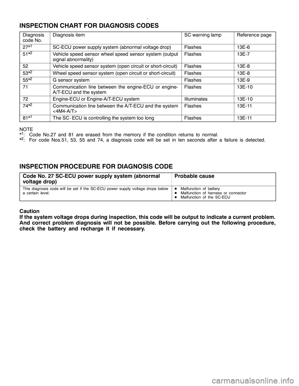
INSPECTION CHART FOR DIAGNOSIS CODES
Diagnosis
code No.Diagnosis itemSC warning lampReference page
27*1SC-ECU power supply system (abnormal voltage drop)Flashes13E-6
51*2Vehicle speed sensor wheel speed sensor system (output
signal abnormality)Flashes13E-7
52Vehicle speed sensor system (open circuit or short-circuit)Flashes13E-8
53*2Wheel speed sensor system (open circuit or short-circuit)Flashes13E-8
55*2G sensor systemFlashes13E-9
71Communication line between the engine-ECU or engine-
A/T-ECU and the systemFlashes13E-10
72Engine-ECU or Engine-A/T-ECU systemIlluminates13E-10
74*2Communication line between the A/T-ECU and the system
<4M4-A/T>Flashes13E-11
81*1The SC - ECU is controlling the system too longFlashes13E-11
NOTE
*1: Code No.27 and 81 are erased from the memory if the condition returns to normal.
*2: For code Nos.51, 53, 55 and 74, a diagnosis code will be set in ten seconds after a failure is detected.
INSPECTION PROCEDURE FOR DIAGNOSIS CODE
Code No. 27 SC-ECU power supply system (abnormal
voltage drop)Probable cause
This diagnosis code will be set if the SC-ECU power supply voltage drops below
a certain level.DMalfunction of battery
DMalfunction of harness or connector
DMalfunction of the SC-ECU
Caution
If the system voltage drops during inspection, this code will be output to indicate a current problem.
And correct problem diagnosis will not be possible. Before carrying out the following procedure,
check the battery and recharge it if necessary.
www.WorkshopManuals.co.uk
Purchased from www.WorkshopManuals.co.uk
Page 596 of 1839
MITSUBISHI SC-Troubleshooting MITSUBISHI SC-Troubleshooting13E-7
OK
NG
Repair
OK
Check the trouble symptoms.
NG
OKNG
Repair
OK
(1)NGCheck the following connectors:
B-25X, D-128, E-122,
E-121
NG
Check the harness wire between the engine control relay and
the SC-ECU, and repair if necessary. (2)NG
OK
Check the trouble symptoms.
NG
Replace
NG
Check the harness wire between the battery and the SC-ECU,
and repair if necessary.
Check the following connectors:
D-27, D-223
D-31
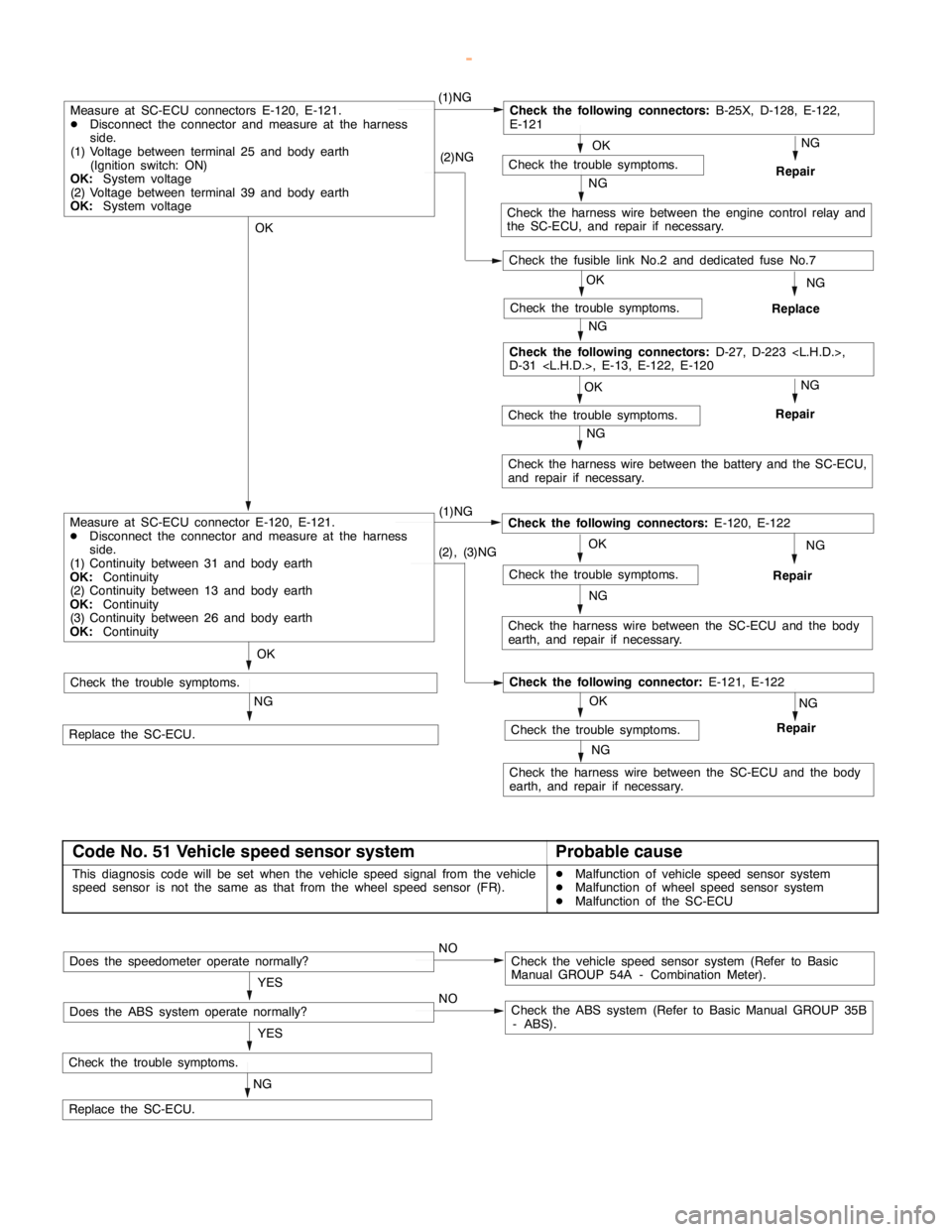
Measure at SC-ECU connectors E-120, E-121.
DDisconnect the connector and measure at the harness
side.
(1) Voltage between terminal 25 and body earth
(Ignition switch: ON)
OK:
System voltage
(2) Voltage between terminal 39 and body earth
OK:
System voltage
NG (1)NG
Check the harness wire between the SC-ECU and the body
earth, and repair if necessary.
Repair
NG
Replace the SC-ECU.
Check the trouble symptoms.
Check the following connectors:
E-120, E-122
NG
(2), (3)NG
Check the harness wire between the SC-ECU and the body
earth, and repair if necessary.
OK
NG
Repair
NGCheck the trouble symptoms.
Check the following connector:
E-121, E-122
OK
Check the trouble symptoms.
Measure at SC-ECU connector E-120, E-121.
DDisconnect the connector and measure at the harness
side.
(1) Continuity between 31 and body earth
OK:
Continuity
(2) Continuity between 13 and body earth
OK:
Continuity
(3) Continuity between 26 and body earth
OK:
Continuity
Check the trouble symptoms.
Check the fusible link No.2 and dedicated fuse No.7
Code No. 51 Vehicle speed sensor systemProbable cause
This diagnosis code will be set when the vehicle speed signal from the vehicle
speed sensor is not the same as that from the wheel speed sensor (FR).DMalfunction of vehicle speed sensor system
DMalfunction of wheel speed sensor system
DMalfunction of the SC-ECU
NG
Check the trouble symptoms.
Replace the SC-ECU.YES
NOCheck the vehicle speed sensor system (Refer to Basic
Manual GROUP 54A - Combination Meter).Does the speedometer operate normally?
YES
NOCheck the ABS system (Refer to Basic Manual GROUP 35B
- ABS).Does the ABS system operate normally?
www.WorkshopManuals.co.uk
Purchased from www.WorkshopManuals.co.uk
Page 597 of 1839
MITSUBISHI SC-Troubleshooting13E-8
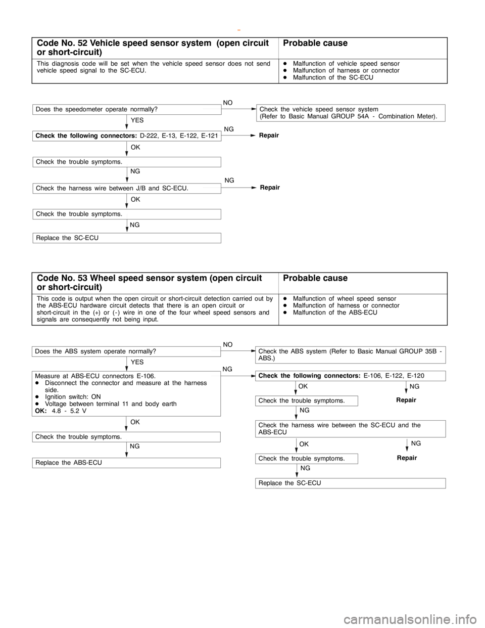
Code No. 52 Vehicle speed sensor system (open circuit
or short-circuit)Probable cause
This diagnosis code will be set when the vehicle speed sensor does not send
vehicle speed signal to the SC-ECU.DMalfunction of vehicle speed sensor
DMalfunction of harness or connector
DMalfunction of the SC-ECU
NG
OK
Repair
NG
Check the trouble symptoms.
Replace the SC-ECUNG
OK
Repair YES
NOCheck the vehicle speed sensor system
(Refer to Basic Manual GROUP 54A - Combination Meter).
NG
Check the following connectors:
D-222, E-13, E-122, E-121
Does the speedometer operate normally?
Check the trouble symptoms.
Check the harness wire between J/B and SC-ECU.
Code No. 53 Wheel speed sensor system (open circuit
or short-circuit)Probable cause
This code is output when the open circuit or short-circuit detection carried out by
the ABS-ECU hardware circuit detects that there is an open circuit or
short-circuit in the (+) or ( - ) wire in one of the four wheel speed sensors and
signals are consequently not being input.DMalfunction of wheel speed sensor
DMalfunction of harness or connector
DMalfunction of the ABS-ECU
OK
NG
Check the trouble symptoms.
Replace the ABS-ECU
OK
NG
Check the harness wire between the SC-ECU and the
ABS-ECU
Check the trouble symptoms.
NG NG
YES
NOCheck the ABS system (Refer to Basic Manual GROUP 35B -
ABS.)
Check the following connectors:
E-106, E-122, E-120
Does the ABS system operate normally?
Measure at ABS-ECU connectors E-106.
DDisconnect the connector and measure at the harness
side.
DIgnition switch: ON
DVoltage between terminal 11 and body earth
OK:
4.8 - 5.2 V
RepairNG
OK
NG
Replace the SC-ECU
Check the trouble symptoms.RepairNG
www.WorkshopManuals.co.uk
Purchased from www.WorkshopManuals.co.uk
Page 604 of 1839
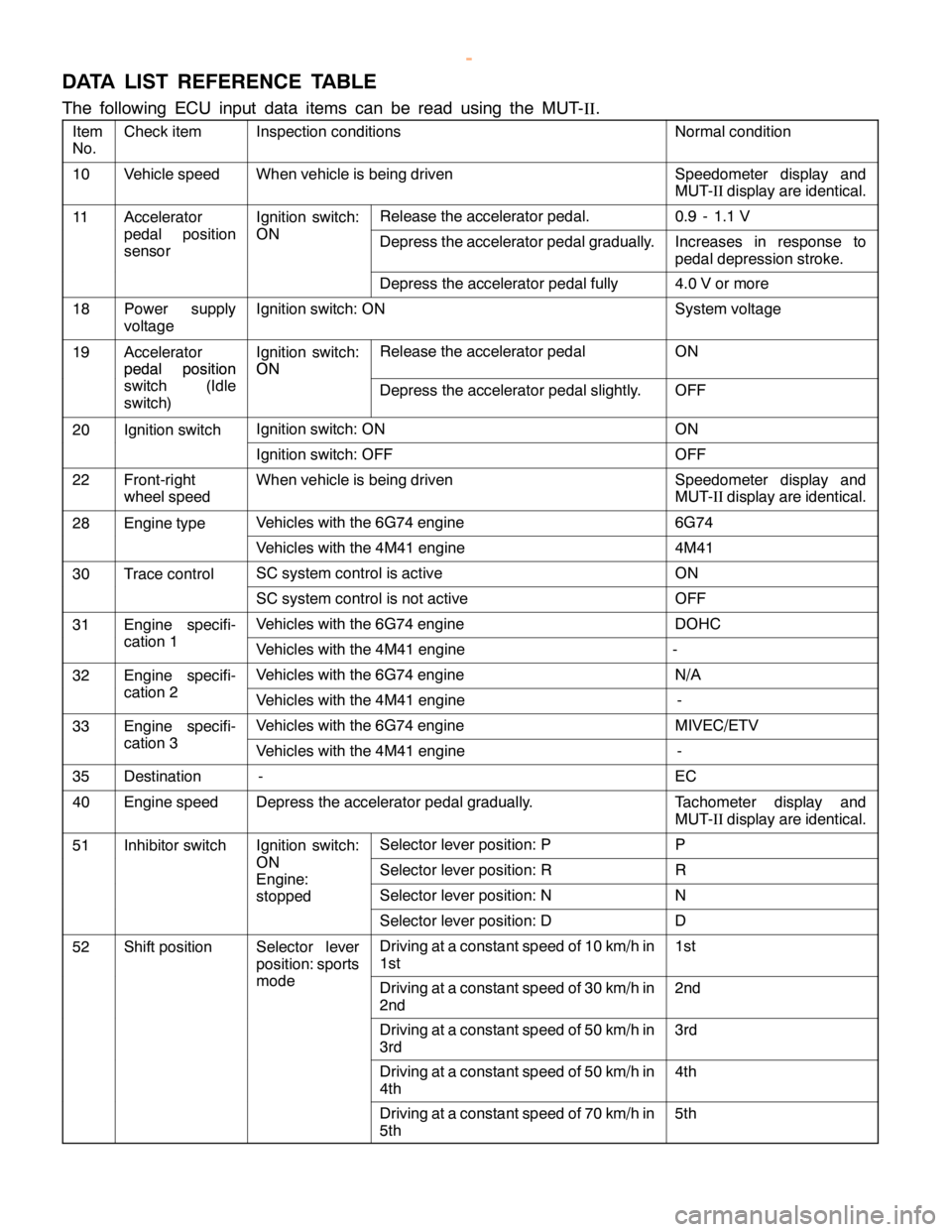
MITSUBISHI SC-Troubleshooting13E-15
DATA LIST REFERENCE TABLE
The following ECU input data items can be read using the MUT-
II.
Item
No.Check itemInspection conditionsNormal condition
10Vehicle speedWhen vehicle is being drivenSpeedometer display and
MUT-IIdisplay are identical.
11AcceleratorIgnition switch:Release the accelerator pedal.0.9 - 1.1 V
pedal position
sensorONDepress the accelerator pedal gradually.Increases in response to
pedal depression stroke.
Depress the accelerator pedal fully4.0 V or more
18Power supply
voltageIgnition switch: ONSystem voltage
19Accelerator
pedal positionIgnition switch:
ONRelease the accelerator pedalON
pedal position
switch (Idle
switch)ON
Depress the accelerator pedal slightly.OFF
20Ignition switchIgnition switch: ONON
Ignition switch: OFFOFF
22Front-right
wheel speedWhen vehicle is being drivenSpeedometer display and
MUT-IIdisplay are identical.
28Engine typeVehicles with the 6G74 engine6G74
Vehicles with the 4M41 engine4M41
30Trace controlSC system control is activeON
SC system control is not activeOFF
31Engine specifi-Vehicles with the 6G74 engineDOHC
cation 1Vehicles with the 4M41 engine-
32Engine specifi-Vehicles with the 6G74 engineN/A
cation 2Vehicles with the 4M41 engine-
33Engine specifi-Vehicles with the 6G74 engineMIVEC/ETV
cation 3Vehicles with the 4M41 engine-
35Destination-EC
40Engine speedDepress the accelerator pedal gradually.Tachometer display and
MUT-IIdisplay are identical.
51Inhibitor switchIgnition switch:Selector lever position: PP
ONSelector lever position: RREngine:
stopped
Selector lever position: NN
Selector lever position: DD
52Shift positionSelector lever
position: sportsDriving at a constant speed of 10 km/h in
1st1st
modeDriving at a constant speed of 30 km/h in
2nd2nd
Driving at a constant speed of 50 km/h in
3rd3rd
Driving at a constant speed of 50 km/h in
4th4th
Driving at a constant speed of 70 km/h in
5th5th
www.WorkshopManuals.co.uk
Purchased from www.WorkshopManuals.co.uk
Page 607 of 1839
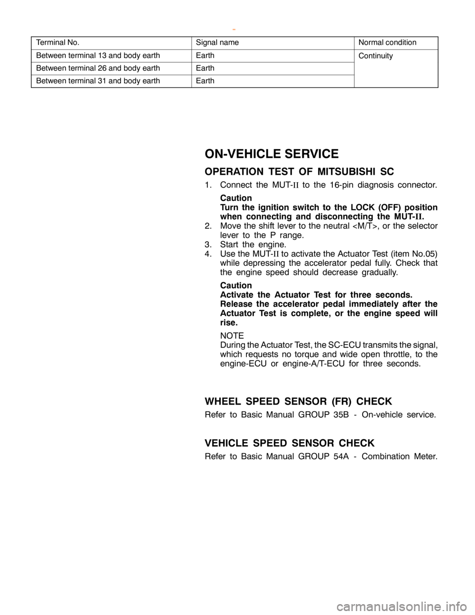
MITSUBISHI SC-Troubleshooting/On-vehicle Service13E-18
Terminal No.Signal nameNormal condition
Between terminal 13 and body earthEarthContinuity
Between terminal 26 and body earthEarth
Between terminal 31 and body earthEarth
ON-VEHICLE SERVICE
OPERATION TEST OF MITSUBISHI SC
1. Connect the MUT-
IIto the 16-pin diagnosis connector.
Caution
Turn the ignition switch to the LOCK (OFF) position
when connecting and disconnecting the MUT-
II.
2. Move the shift lever to the neutral
lever to the P range.
3. Start the engine.
4. Use the MUT-
IIto activate the Actuator Test (item No.05)
while depressing the accelerator pedal fully. Check that
the engine speed should decrease gradually.
Caution
Activate the Actuator Test for three seconds.
Release the accelerator pedal immediately after the
Actuator Test is complete, or the engine speed will
rise.
NOTE
During the Actuator Test, the SC-ECU transmits the signal,
which requests no torque and wide open throttle, to the
engine-ECU or engine-A/T-ECU for three seconds.
WHEEL SPEED SENSOR (FR) CHECK
Refer to Basic Manual GROUP 35B - On-vehicle service.
VEHICLE SPEED SENSOR CHECK
Refer to Basic Manual GROUP 54A - Combination Meter.
www.WorkshopManuals.co.uk
Purchased from www.WorkshopManuals.co.uk
Page 719 of 1839
INTAKE AND EXHAUST -Intake and Exhaust Manifold,
Turbocharger <4D5>15-13
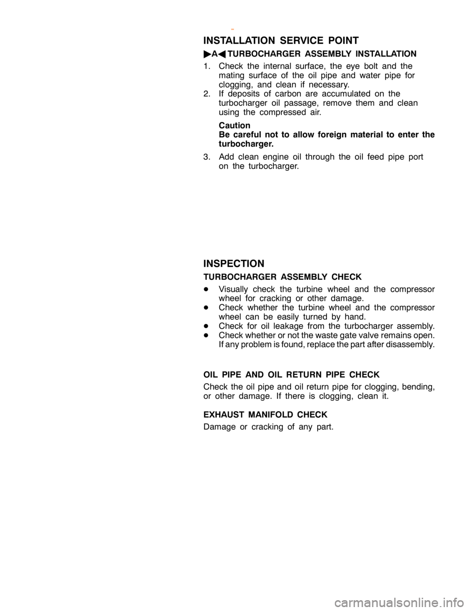
INSTALLATION SERVICE POINT
"
AA
TURBOCHARGER ASSEMBLY INSTALLATION
1. Check the internal surface, the eye bolt and the
mating surface of the oil pipe and water pipe for
clogging, and clean if necessary.
2. If deposits of carbon are accumulated on the
turbocharger oil passage, remove them and clean
using the compressed air.
Caution
Be careful not to allow foreign material to enter the
turbocharger.
3. Add clean engine oil through the oil feed pipe port
on the turbocharger.
INSPECTION
TURBOCHARGER ASSEMBLY CHECK
DVisually check the turbine wheel and the compressor
wheel for cracking or other damage.
DCheck whether the turbine wheel and the compressor
wheel can be easily turned by hand.
DCheck for oil leakage from the turbocharger assembly.
DCheck whether or not the waste gate valve remains open.
If any problem is found, replace the part after disassembly.
OIL PIPE AND OIL RETURN PIPE CHECK
Check the oil pipe and oil return pipe for clogging, bending,
or other damage. If there is clogging, clean it.
EXHAUST MANIFOLD CHECK
Damage or cracking of any part.
www.WorkshopManuals.co.uk
Purchased from www.WorkshopManuals.co.uk