Page 523 of 1839

DIESEL FUEL <4M4> -Troubleshooting13C-32
DATA LIST REFERENCE TABLE
Item
No.Check itemInspection conditionsValue to be
determined
as normalCode No.
or inspec-
tion proce-
dure No.Reference
page
01Boost air
temperatureIgnition switch: ON or
the engine runningWhen the intake air
temperature is - 20_C-20_CCode No.
1613C-11
sensorWhen the intake air
temperature is 0_C0_C
When the intake air
temperature is 20_C20_C
When the intake air
temperature is 40_C40_C
When the intake air
temperature is 80_C80_C
02Engine cool-
ant temper-
ature sensorIgnition switch: ON or
the engine runningWhen the engine cool-
ant temperature is
-20_C-20_CCode No.
1513C-11
When the engine cool-
ant temperature is
0_C0_C
When the engine cool-
ant temperature is
20_C20_C
When the engine cool-
ant temperature is
40_C40_C
When the engine cool-
ant temperature is
80_C80_C
03BarometricIgnition switch: ONAltitude 0 m101 kPaCode No.13C-10
pressureAltitude 600 m95 kPa13
sensorAltitude 1,200 m88 kPa
Altitude 1,800 m81 kPa
04Boost pres-DEngine coolantAltitude 0 m101 kPaCode No.13C-9
sure sensortemperature:Altitude 600 m95 kPa12
80 - 95_C
DLamps, electricalAltitude 1,200 m88 kPa
cooling fan, andAltitude 1,800 m81 kPaaccessories: OFF
DTransmission: PIdling81 - 109 kPaDTransmission: P
range
DIgnition switch: ON
When sudden racing is
doneIncreased
05Fuel tem-
peratureIgnition switch: ON or
the engine runningWhen the fuel temper-
ature is - 20_C-20_CCode No.
1413C-10
sensorWhen the fuel temper-
ature is 0_C0_C
When the fuel temper-
ature is 20_C20_C
When the fuel temper-
ature is 40_C40_C
When the fuel temper-
ature is 80_C80_C
www.WorkshopManuals.co.uk
Purchased from www.WorkshopManuals.co.uk
Page 650 of 1839

DIESEL FUEL <4D5-stepIII>-Troubleshooting13E-40
DATA LIST REFERENCE TABLE
Item
No.Check itemInspection conditionsValue to be
determined
as normalCode No.
or inspec-
tion proce-
dure No.Reference
page
01Boost air
temperatureIgnition switch: ON or
the engine runningWhen the intake air
temperature is - 20_C-20_CCode No.
1613E-12
p
sensor
gg
When the intake air
temperature is 0_C0_C
When the intake air
temperature is 20_C20_C
When the intake air
temperature is 40_C40_C
When the intake air
temperature is 80_C80_C
02Engine
coolant
temperatureIgnition switch: ON or
the engine runningWhen the engine
coolant temperature is
-20_C-20_CCode No.
1513E-12
p
sensorWhen the engine
coolant temperature is
0_C0_C
When the engine
coolant temperature is
20_C20_C
When the engine
coolant temperature is
40_C40_C
When the engine
coolant temperature is
80_C80_C
03BarometricIgnition switch: ONAltitude 0 m101 kPaCode No.
13
13E-11
pressure
sensor
g
Altitude 600 m95 kPa13
sensorAltitude 1,200 m88 kPa
Altitude 1,800 m81 kPa
04BoostDEngine coolant
tt
Altitude 0 m101 kPaCode No.
12
13E-10
pressure
sensor
g
temperature:
80-95_CAltitude 600 m95 kPa12
sensor80-95_C
DLamps, electricalAltitude 1,200 m88 kPaLamps,electrical
cooling fan, and
accessories:OFFAltitude 1,800 m81 kPaaccessories:OFF
DTransmission:Idling81 - 109 kPaDTransmission:
Neutral
DIgnition switch: ONWhen sudden racing is
doneIncreased
05Fuel
temperatureIgnition switch: ON or
the engine runningWhen the fuel
temperature is - 20_C-20_CCode No.
1413E-11
p
sensor
gg
When the fuel
temperature is 0_C0_C
When the fuel
temperature is 20_C20_C
When the fuel
temperature is 40_C40_C
When the fuel
temperature is 80_C80_C
www.WorkshopManuals.co.uk
Purchased from www.WorkshopManuals.co.uk
Page 880 of 1839
MANUAL
TRANSMISSION
Click on the applicable bookmark to selected the required model year.
www.WorkshopManuals.co.uk
Purchased from www.WorkshopManuals.co.uk
Page 881 of 1839
22-1
MANUAL
TRANSMISSION
CONTENTS
GENERAL INFORMATION 2..................
LUBRICANTS 2..............................
SEALANTS 2................................
SPECIAL TOOL 2............................
TROUBLESHOOTING 3.............
ON-VEHICLE SERVICE 6.....................
Transmission Oil Check 6.......................
Oil Replacement 6.............................4WD Detection Switch Continuity Check
7...................................
High/Low Detection Switch Continuity Check
7...................................
TRANSMISSION CONTROL 8.......
TRANSMISSION CONTROL 9.......
TRANSMISSION ASSEMBLY 10..............
4WD INDICATOR-ECU/TRANSFER-ECU 17....
www.WorkshopManuals.co.uk
Purchased from www.WorkshopManuals.co.uk
Page 883 of 1839

MANUAL TRANSMISSION -Troubleshooting 22-3
TROUBLESHOOTING
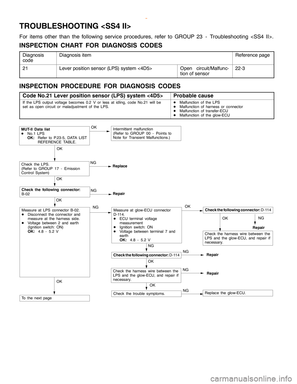
For items other than the following service procedures, refer to GROUP 23 - Troubleshooting .
INSPECTION CHART FOR DIAGNOSIS CODES
Diagnosis
codeDiagnosis itemReference page
21Lever position sensor (LPS) system <4D5>Open circuit/Malfunc-
tion of sensor22-3
INSPECTION PROCEDURE FOR DIAGNOSIS CODES
Code No.21 Lever position sensor (LPS) system <4D5>Probable cause
If the LPS output voltage becomes 0.2 V or less at idling, code No.21 will be
set as opencircuit or maladjustment of the LPS.DMalfunction of the LPS
DMalfunction of harness or connector
DMalfunction of transfer-ECU
DMalfunction of the glow-ECU
NGOK
NG
Repair
MUT-II Data list
DNo.1 LPS
OK:Refer to P.23-5, DATA LIST
REFERENCE TABLE.
NG
ReplaceCheck the LPS.
(Refer to GROUP 17 - Emission
Control System)
OK
NG
Repair
OK
Check the following connector:
B-02
OK
OK
Check the following connector:D-114
Repair
NG
Repair
NG
Repair
OK
OK
Check the following connector:D-114
Measure at glow-ECU connector
D-114.
DECU terminal voltage
measurement
DIgnition switch: ON
DVoltage between terminal 7 and
earth
OK:4.8 - 5.2 V
NGNG
NGCheck the trouble symptoms.
OK
Measure at LPS connector B-02.
DDisconnect the connector and
measure at the harness side.
DVoltage between 2 and earth
(Ignition switch: ON)
OK:4.8 - 5.2 V
To the nextpage
Intermittent malfunction
(Refer to GROUP 00 - Points to
Note for Transient Malfunctions.)
OK
Check the harness wire between the
LPS and the glow-ECU, and repair if
necessary.
Check the harness wire between the
LPS and the glow-ECU, and repair if
necessary.
Replace the glow-ECU.
www.WorkshopManuals.co.uk
Purchased from www.WorkshopManuals.co.uk
Page 884 of 1839

MANUAL TRANSMISSION -Troubleshooting 22-4
OKOKOK
NG
NG
NG(1),(2) NG
Check the following connector:D-114
Repair OK
OK
OK
Measure at transfer-ECU connector
E-105.
DECU terminal voltage
measurement
DIgnition switch: ON
DVoltage between terminal 5 and
earth
OK:Acceleratorpedalfully
closed
800 - 1,000 mV
Acceleratorpedalfully de-
pressed
3,700 - 4,900 mV
Check the following connector:E-105
Check the trouble symptoms.OK
Check the following connectors:
E-105, E-113 NG
Replace the transfer-ECU. OK
NGRepairAdjust
Check the harness wire between the
LPS and the transfer-ECU, and
repair if necessary.
Check the harness wire between the
LPS and the transfer-ECU, and
repair if necessary.
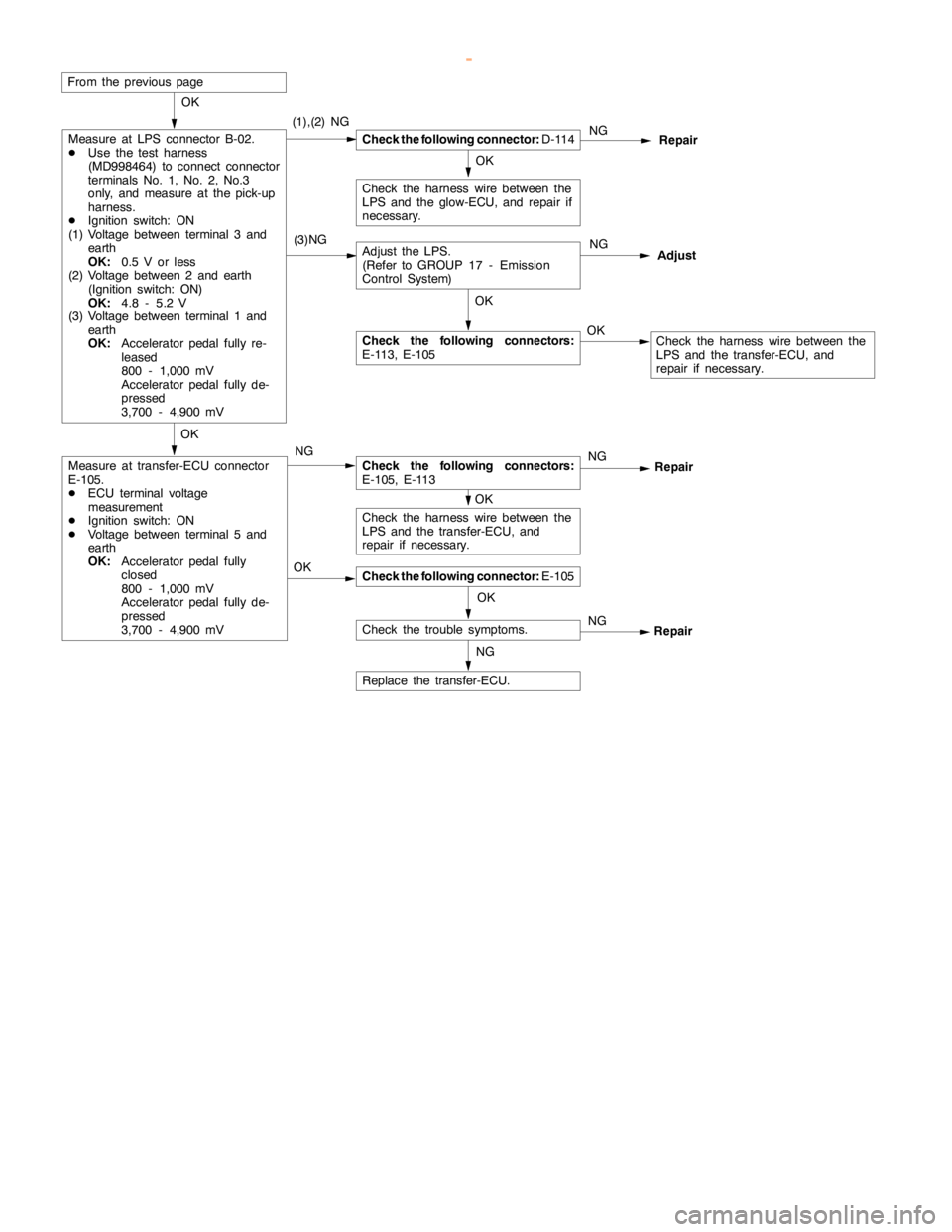
From the previouspage
(3)NG
Measure at LPS connector B-02.
DUse the test harness
(MD998464) to connect connector
terminals No. 1, No. 2, No.3
only, and measure at the pick-up
harness.
DIgnition switch: ON
(1) Voltage between terminal 3 and
earth
OK:0.5 V or less
(2) Voltage between 2 and earth
(Ignition switch: ON)
OK:4.8 - 5.2 V
(3) Voltage between terminal 1 and
earth
OK:Acceleratorpedalfully re-
leased
800 - 1,000 mV
Acceleratorpedalfully de-
pressed
3,700 - 4,900 mV
NGAdjust the LPS.
(Refer to GROUP 17 - Emission
Control System)
Check the following connectors:
E-113, E-105
Repair
Check the harness wire between the
LPS and the glow-ECU, and repair if
necessary.
www.WorkshopManuals.co.uk
Purchased from www.WorkshopManuals.co.uk
Page 885 of 1839
MANUAL TRANSMISSION -Troubleshooting 22-5
DATA LIST REFERENCE TABLE
Data
list No.Check itemCheck conditionsNormal condition
1Lever positionEngine: StoppedAccelerator pedal: Fully closed800 - 1,000 mV
sensor (LPS)
<4D5>Selector lever position:
PAccelerator pedal: DepressedGradually increases from
the above value.
Accelerator pedal: Fully open3,700 - 4,900 mV
CHECK AT TRANSFER-ECU TERMINAL
Ter-
minal
No.Check itemCheck conditionsStandard value
5Lever position sensorAccelerator pedal: Fully closed (engine stopped)0.8 - 1.0 V
(LPS) <4D5>Accelerator pedal: Fully open (engine stopped)3.7 - 4.9 V
www.WorkshopManuals.co.uk
Purchased from www.WorkshopManuals.co.uk
Page 893 of 1839
MANUAL TRANSMISSION -Transmission Assembly22-13
9. Dynamic damper
10. Tension wire bracket
DSupport the transmission with a
transmission jack
11. Transmission mount center member
assembly
12. Transmission mount insulator assem-
blyA
A"13. Transmission harness connector con-
nection
A
B"DClutch release bearing disconnection
"
AA14. Transmission assembly
15. Tension wire
www.WorkshopManuals.co.uk
Purchased from www.WorkshopManuals.co.uk