Page 1213 of 1839

BASIC BRAKE SYSTEM -Service Specifications35A-5
SERVICE SPECIFICATIONS
ItemsStandard valueLimit
Brake pedal heightL.H. drive vehicles192 - 195-
mm
R.H. drive vehicles187 - 190-
Brake pedal play mm3-8-
Brake pedal to floorboard clearance when the brake pedal is depressed mm90 or more-
Hydraulic brake
booster (HBB)Pump motor
operation timeWhen power supply system brake fluid
pressure is not applied20 - 80-
second
When power supply system brake fluid
pressure is applied2-11-
Hydraulic pressurePedal depressionFront0.6 or more-
during no vacuum
operation testforce: 100 N
Rear0-
MPa
Pedal depressionFront4.5 or more-
force: 500 N
Rear0-
Hydraulic pressurePedal depressionFront3.0 - 4.0-
during vacuum op-
eration test
MPa
force: 100 N
Rear3.3 - 4.3-
Pedal depressionFront8.0 - 10.0-
force: 200 N
Rear8.0 - 10.0-
Pedal depressionFront14.0 - 18.0-
force: 400 N
Rear14.0 - 18.0-
Pedal depressionFront15.0 - 19.0-
force: 500 N
Rear15.0 - 19.0-
Clearance between brake booster push rod and primary piston6G70.5 - 0.9-
mm
4D5, 4M40.8 - 1.2-
Load sensing propor-When load sensing spring length is 133Short wheelbase4.9 - 5.9 (9.8)-
tioning valve output
fluid pressure (Inputmm (when unladen)
Long wheelbase5.9 - 6.9 (9.8)-
fluid pressure) MPa
ABS>mm (when laden)
9.0 - 11.0
(16.7)-
Long wheelbase9.3 - 10.3 (9.8)-
11.4 - 13.4
(16.7)-
Load sensing spring length mm
135 - 139-
www.WorkshopManuals.co.uk
Purchased from www.WorkshopManuals.co.uk
Page 1220 of 1839

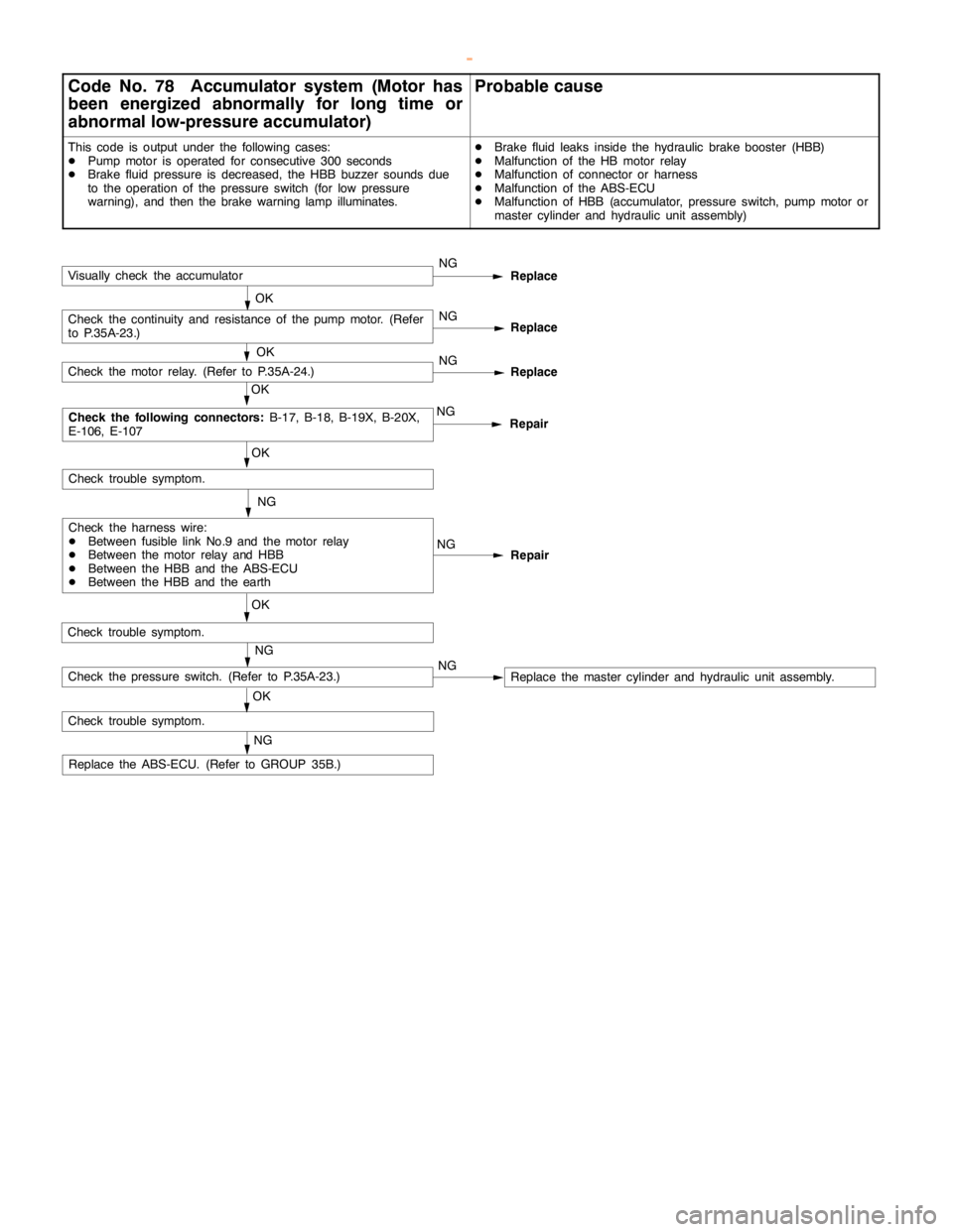
BASIC BRAKE SYSTEM -Troubleshooting35A-12
Code No. 78 Accumulator system (Motor has
been energized abnormally for long time or
abnormal low-pressure accumulator)Probable cause
This code is output under the following cases:
DPump motor is operated for consecutive 300 seconds
DBrake fluid pressure is decreased, the HBB buzzer sounds due
to the operation of the pressure switch (for low pressure
warning), and then the brake warninglamp illuminates.DBrake fluid leaks inside the hydraulic brake booster (HBB)
DMalfunction of the HB motor relay
DMalfunction of connector or harness
DMalfunction of the ABS-ECU
DMalfunction of HBB (accumulator, pressure switch,pump motor or
master cylinder and hydraulic unit assembly)
NG
Repair
NG
OK
Check trouble symptom.
Repair NGNG
OK
Check trouble symptom.
Replace
OK
Check the following connectors:
B-17, B-18, B-19X, B-20X,
E-106, E-107
Check the harness wire:
DBetween fusible link No.9 and the motor relay
DBetween the motor relay and HBB
DBetween the HBB and the ABS-ECU
DBetween the HBB and the earthNG
Check the motor relay. (Refer to P.35A-24.)
NG
Replace the ABS-ECU. (Refer to GROUP 35B.)
Check trouble symptom.
NG
OKCheck the pressure switch. (Refer to P.35A-23.)NG
Replace
OKCheck the continuity and resistance of thepump motor.(Refer
to P.35A-23.)NG
Replace
OKVisually check the accumulator
Replace the master cylinder and hydraulic unit assembly.
www.WorkshopManuals.co.uk
Purchased from www.WorkshopManuals.co.uk
Page 1235 of 1839

BASIC BRAKE SYSTEM -On-vehicle ServiceBASIC BRAKE SYSTEM -On-vehicle Service35A-27
BLEEDING
Caution
Specified brake fluid: DOT3 or DOT4
1. Always use the specified brake fluid. Avoid using
a mixture of the specified brake fluid and other fluid.
2. Maintain the fluid reservoir level between the MIN
and MAX marks during the air bleeding.
3. Do not depress the brake pedal hard during the air
bleeding (normal air bleeding) to prevent the pump
motor from operating frequently.
4. After the air bleeding, check that the brake dragging
does not become stronger.
5. If the pedal is depressed with the reservoir cap
removed, the brake fluid may overflow. Do not depress
the brake pedal while the fluid is being added.
NORMAL AIR BLEEDING
After the front brake or the rear brake is removed and installed,
some fluid may remain in the hydraulic brake booster (HBB)
reservoir. In this case, bleed air from the brake caliper.
HBB SYSTEM AIR BLEEDING
If all the brake fluid inside the reservoir is drained due to
the removal and installation of the HBB, bleed air as follows:
Air bleeding from front brake system
1. Turn the ignition switch to the LOCK (OFF) position. Bleed
air from the front brake calipers (right and left) by pumping
the brake pedal.
Pump motor operation
2. Turn the ignition switch ON, and operate the pump motor.
If the pump motor is running free, supply the brake fluid
into the pump motor by depressing the brake pedal three
or four times.
Air bleeding from accumulator system
3. After the pump motor stopped, depress the brake pedal
three or four times with the ignition switch ON. Then
observe the brake fluid in the reservoir. If the brake fluid
looks whitish, wait for a few minutes until it becomes
clear.
4. Repeat step 3 until the brake fluid becomes clear.
www.WorkshopManuals.co.uk
Purchased from www.WorkshopManuals.co.uk
Page 1264 of 1839

35B-1
ANTI-SKID
BRAKING SYSTEM
(ABS) <4WD>
CONTENTS
GENERAL INFORMATION 2..................
SERVICE SPECIFICATIONS 4.................
LUBRICANT Refer to GROUP 35A...........
SEALANTS Refer to GROUP 35A............
SPECIAL TOOLS 4..........................
TROUBLESHOOTING 4.......................
ON-VEHICLE SERVICE 27...................
Wheel Speed Sensor Output Voltage
Measurement 27...............................
ABS Valve Relay Continuity Check 28...........
Hydraulic Brake Booster (HBB) - Hydraulic Unit
Check 29......................................
Solenoid Valve Check 30.......................
When the Battery is Flat 31....................
Brake Pedal Check and Adjustment
Refer to GROUP 35A ..........................
Hydraulic Brake Booster (HBB) Operation Check
Refer to GROUP 35A ..........................
Hydraulic Brake Booster (HBB) Check
Refer to GROUP 35A ..........................Motor Relay Continuity Check
Refer to GROUP 35A ..........................
Bleeding Refer to GROUP 35A..................
Brake Fluid Level Sensor Check
Refer to GROUP 35A ..........................
Disc Brake Pad Check and Replacement
Refer to GROUP 35A ..........................
Brake Disc Thickness Check
Refer to GROUP 35A ..........................
Brake Disc Runout Check and Correction
Refer to GROUP 35A ..........................BRAKE PEDAL Refer to GROUP 35A........
HYDRAULIC BRAKE BOOSTER (HBB)
Refer to GROUP 35A ........................
HBB BUZZER Refer to GROUP 35A..........
FRONT DISC BRAKE Refer to GROUP 35A..
REAR DISC BRAKE Refer to GROUP 35A....
ABS-ECU 32................................
WHEEL SPEED SENSOR 33.................
G-SENSOR 36..............................
www.WorkshopManuals.co.uk
Purchased from www.WorkshopManuals.co.uk