2000 MITSUBISHI MONTERO brake
[x] Cancel search: brakePage 531 of 1839

DIESEL FUEL <4M4> -Troubleshooting13C-40
Terminal
No.Normal condition: Inspection conditions (engine status) Check item
36Selector switch be-
tween A/T and M/TIgnition switch: ON0-1V
37Inhibitor switchIgnition switch: ON
(Engine stops)Set the selector lever to P
or N0-1V
Set the selector lever to D,
2, L, or RSystem voltage
39Stop lamp switchDepress the brake pedalSystem voltage
40Brake switchDepress the brake pedal0-1V
46Control relayIgnition switch: ON0-1V
Ignition switch: ON®OFF (in about 8 seconds)System voltage
51Engine speed sensor
(backup)Engine: Idling1.5 - 2.5 V
55Accelerator pedal posi-
tion sensor (sub)Ignition switch: ONAccelerator pedal: Idling
position0.9 - 1.1 V
Accelerator pedal: Fully
opened position4.1 V or higher
71Ignition switch-STEngine: Cranking8 V or higher
74Control sleeve positionIgnition switch: ON (Engine stops)2.2 - 2.7 V
73sensor2.0 - 4.0 V
752.0 - 4.0 V
76Timer piston positionIgnition switch: ON (Engine stops)2.2 - 2.7 V
77sensor2.0 - 4.0 V
782.0 - 4.0 V
80Back-up power supplyIgnition switch: OFFSystem voltage
82Ignition switch-IGIgnition switch: ONSystem voltage
83Engine coolant tem-
perature sensorIgnition switch: ONEngine coolant tempera-
ture: 0_C3.4 - 4.5 V
Engine coolant tempera-
ture: 20_C2.6 - 3.6 V
Engine coolant tempera-
ture: 40_C1.8 - 2.5 V
Engine coolant tempera-
ture: 80_C0.7 - 1.1 V
84Accelerator pedal posi-
tion sensor (main)Ignition switch: ONAccelerator pedal: Idling
position0.9 - 1.1 V
Accelerator pedal: Fully
opened position4.1 V or higher
85Boost pressure sensorIgnition switch: ON (760 mmHg)1.2 - 1.6 V
86Vehicle speed sensorDIgnition switch: ON
DMove the vehicle forward slowly0V«5 V (repeat the
change)
www.WorkshopManuals.co.uk
Purchased from www.WorkshopManuals.co.uk
Page 658 of 1839

DIESEL FUEL <4D5-stepIII>-Troubleshooting13E-48
Terminal
No.Normal condition: Inspection conditions (engine status) Check item
88Boost air temperature
sensorIgnition switch: ONIntake air temperature:
0_C3.2 - 3.8 V
Intake air temperature:
20_C2.3 - 2.9 V
Intake air temperature:
40_C1.4 - 2.0 V
Intake air temperature:
80_C0.4 - 1.0 V
89Crank angle sensorEngine: Idling (Use a digital voltage meter to check.)0V↔5V
(repeat the change)
90EGR valve position
sensor
Engine: After warm-
inguptheengine
Idling under no load2.3 - 3.3 V
sensoring up the engineEngine is suddenly racedMomentarily drops from
voltage during idling
91Parking switchIgnition switch: ON
(Enginestops)
Parking brake: ON0-1V
(Engine stops)Parking brake: OFFSystem voltage
CHECK CHART FOR RESISTANCE AND CONTINUITY
BETWEEN TERMINALS
1. Turn the ignition switch to LOCK (OFF) position.
2. Disconnect the engine-ECU connector.
3. Measure the resistance and check for continuity between
the terminals of the engine-ECU harness-side connector
while referring to the check chart.
NOTE
(1) When measuring resistance and checking continuity,
a harness for checking contact pin pressure should
be used instead of inserting a test probe.
(2) Checking need not be carried out in the order given
in the chart.
Caution
If the terminals that should be checked are mistaken,
or if connector terminals are not correctly shorted
to earth, damage may be caused to the vehicle wiring,
sensors, engine-ECU and/or ohmmeter.
Be careful to prevent this!
4. If the ohmmeter shows any deviation from the standard
value, check the corresponding sensor, actuator and
related electrical wiring, and then repair or replace.
5. After repair or replacement, recheck with the ohmmeter
to confirm that the repair or replacement has corrected
the problem.
www.WorkshopManuals.co.uk
Purchased from www.WorkshopManuals.co.uk
Page 813 of 1839
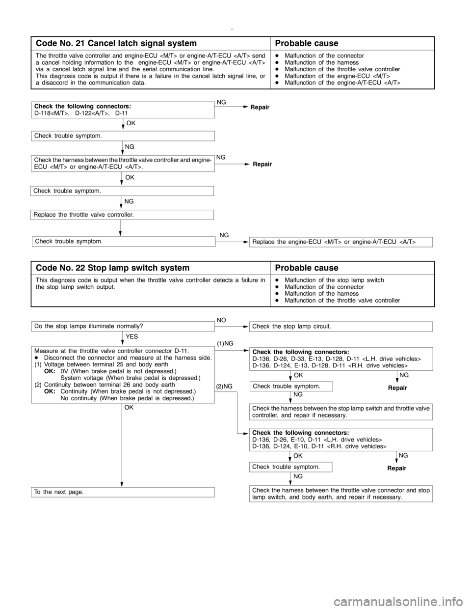
ENGINE AND EMISSION CONTROL -Auto-cruise Control System17-11
Code No. 21 Cancel latch signal systemProbable cause
The throttle valve controller and engine-ECU
a cancelholding information to the engine-ECU
via a cancel latch signal line and the serial communication line.
This diagnosis code is output if there is a failure in the cancel latch signal line, or
a disaccord in the communication data.DMalfunction of the connector
DMalfunction of the harness
DMalfunction of the throttle valve controller
DMalfunction of the engine-ECU
DMalfunction of the engine-A/T-ECU
Repair NG
RepairCheck the following connectors:
D-118
OK
Replace the throttle valve controller.
NG
NG
Check the harness between the throttle valve controller and engine-
ECU
Replace the engine-ECU
Check trouble symptom.
OK
Check trouble symptom.
Check trouble symptom.NG
Code No. 22 Stop lamp switch systemProbable cause
This diagnosis code is output when the throttle valve controller detects a failure in
the stoplampswitch output.DMalfunction of the stoplampswitch
DMalfunction of the connector
DMalfunction of the harness
DMalfunction of the throttle valve controller
(2)NG
NG
Check the harness between the throttle valve connector and stop
lampswitch, and body earth, and repair if necessary.
NG
Repair
OK
Check trouble symptom.
Measure at the throttle valve controller connector D-11.
DDisconnect the connector and measure at the harness side.
(1) Voltage between terminal 25 and body earth
OK:0V (When brakepedal is not depressed.)
System voltage (When brakepedal is depressed.)
(2) Continuity between terminal 26 and body earth
OK:Continuity (When brakepedal is not depressed.)
No continuity (When brakepedal is depressed.)NO
Do the stop lamps illuminate normally?
OK
To the next page.
Check the following connectors:
D-136, D-26, D-33, E-13, D-128, D-11
D-136, D-124, E-13, D-128, D-11
OK
Check trouble symptom.
NG
Check the harness between the stoplampswitch and throttle valve
controller, and repair if necessary.NG
Repair
Check the stoplampcircuit.
YES
(1)NG
Check the following connectors:
D-136, D-26, E-10, D-11
D-136, D-124, E-10, D-11
www.WorkshopManuals.co.uk
Purchased from www.WorkshopManuals.co.uk
Page 814 of 1839
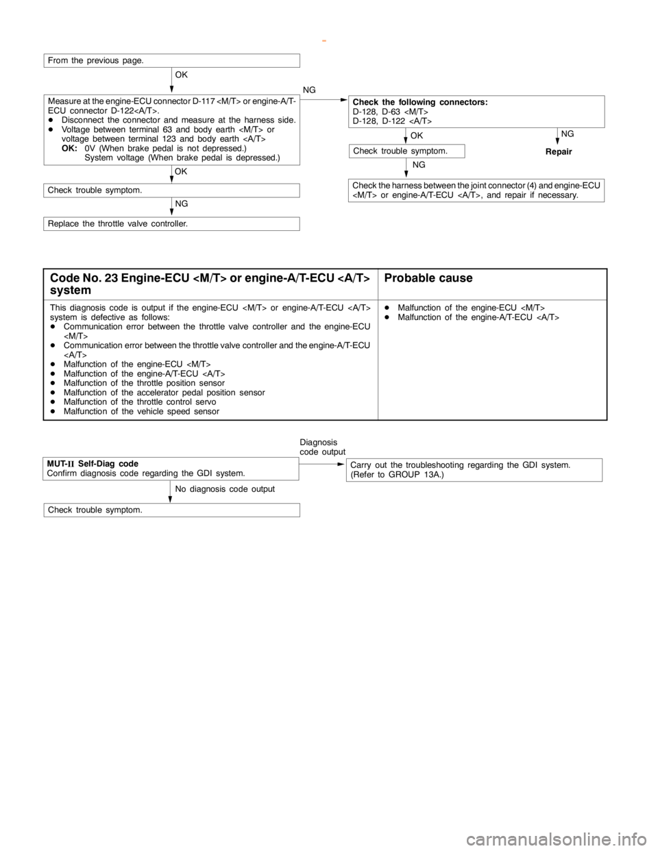
ENGINE AND EMISSION CONTROL -Auto-cruise Control System17-12
NG
Check the harness between the joint connector (4) and engine-ECU
NG
Repair
OK
Check trouble symptom.
From the previous page.
OK
Check the following connectors:
D-128, D-63
D-128, D-122
OK
Check trouble symptom.
NG
Replace the throttle valve controller.NG
Measure at the engine-ECU connector D-117
ECU connector D-122.
DDisconnect the connector and measure at the harness side.
DVoltage between terminal 63 and body earth
voltage between terminal 123 and body earth
OK:0V (When brakepedal is not depressed.)
System voltage (When brakepedal is depressed.)
Code No. 23 Engine-ECU
systemProbable cause
This diagnosis code is output if the engine-ECU
system is defective as follows:
DCommunication error between the throttle valve controller and the engine-ECU
DCommunication error between the throttle valve controller and the engine-A/T-ECU
DMalfunction of the engine-ECU
DMalfunction of the engine-A/T-ECU
DMalfunction of the throttle position sensor
DMalfunction of the accelerator pedal positionsensor
DMalfunction of the throttle control servo
DMalfunction of the vehicle speed sensorDMalfunction of the engine-ECU
DMalfunction of the engine-A/T-ECU
MUT-
IISelf-Diag code
Confirm diagnosis code regarding the GDI system.Diagnosis
code outputCarry out the troubleshooting regarding the GDI system.
(Refer to GROUP 13A.)
No diagnosis code output
Check trouble symptom.
www.WorkshopManuals.co.uk
Purchased from www.WorkshopManuals.co.uk
Page 816 of 1839
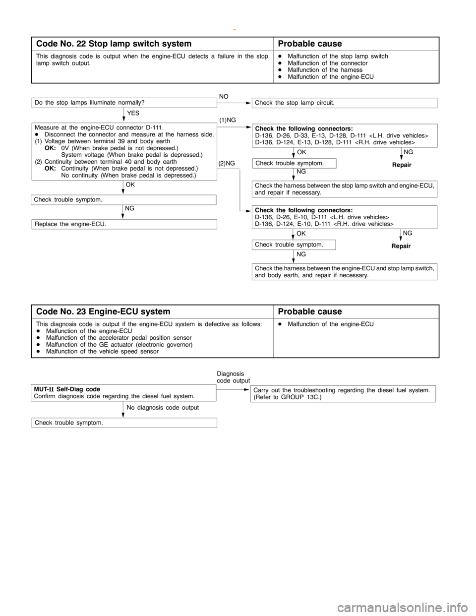
ENGINE AND EMISSION CONTROL -Auto-cruise Control System17-14
Code No. 22 Stop lamp switch systemProbable cause
This diagnosis code is output when the engine-ECU detects a failure in the stop
lampswitch output.DMalfunction of the stoplampswitch
DMalfunction of the connector
DMalfunction of the harness
DMalfunction of the engine-ECU
(2)NG
NG
Check the harness between the engine-ECU and stoplampswitch,
and body earth, and repair if necessary.
NG
Repair
OK
Check trouble symptom.
Measure at the engine-ECU connector D-111.
DDisconnect the connector and measure at the harness side.
(1) Voltage between terminal 39 and body earth
OK:0V (When brakepedal is not depressed.)
System voltage (When brakepedal is depressed.)
(2) Continuity between terminal 40 and body earth
OK:Continuity (When brakepedal is not depressed.)
No continuity (When brakepedal is depressed.)NO
Do the stop lamps illuminate normally?
OK
Check trouble symptom.
Check the following connectors:
D-136, D-26, D-33, E-13, D-128, D-111
D-136, D-124, E-13, D-128, D-111
OK
Check trouble symptom.
NG
Check the harness between the stoplampswitch and engine-ECU,
and repair if necessary.NG
Repair
Check the stoplampcircuit.
YES
(1)NG
Check the following connectors:
D-136, D-26, E-10, D-111
D-136, D-124, E-10, D-111
Replace the engine-ECU.
Code No. 23 Engine-ECU systemProbable cause
This diagnosis code is output if the engine-ECU system is defective as follows:
DMalfunction of the engine-ECU
DMalfunction of the accelerator pedal positionsensor
DMalfunction of the GE actuator (electronic governor)
DMalfunction of the vehicle speed sensorDMalfunction of the engine-ECU
MUT-
IISelf-Diag code
Confirm diagnosis code regarding the diesel fuel system.Diagnosis
code outputCarry out the troubleshooting regarding the diesel fuel system.
(Refer to GROUP 13C.)
No diagnosis code output
Check trouble symptom.
www.WorkshopManuals.co.uk
Purchased from www.WorkshopManuals.co.uk
Page 817 of 1839
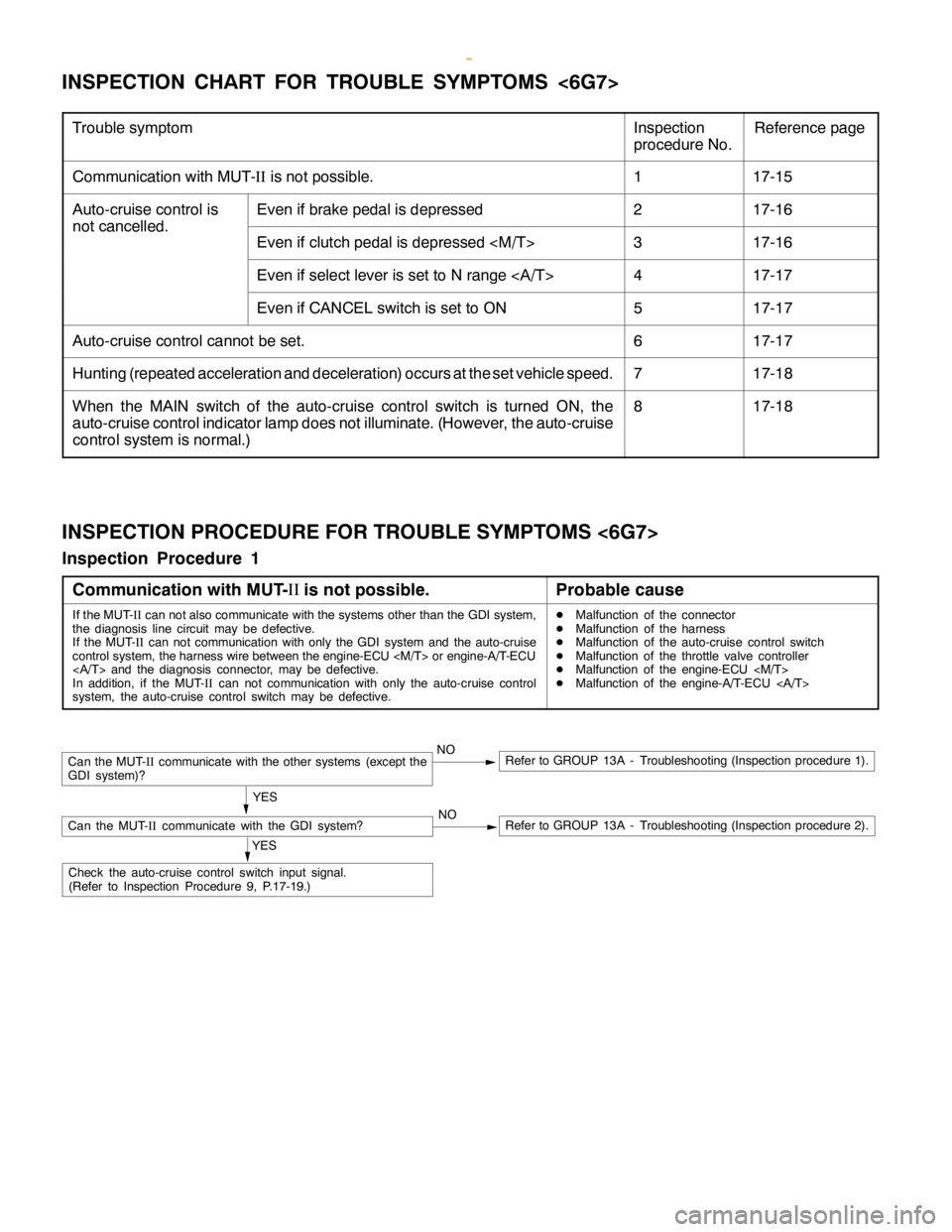
ENGINE AND EMISSION CONTROL -Auto-cruise Control SystemENGINE AND EMISSION CONTROL -Auto-cruise Control System17-15
INSPECTION CHART FOR TROUBLE SYMPTOMS <6G7>
Trouble symptomInspection
procedure No.Reference page
Communication with MUT-IIis not possible.117-15
Auto-cruise control isEven if brake pedal is depressed217-16
not cancelled.
Even if clutch pedal is depressed
Even if select lever is set to N range417-17
Even if CANCEL switch is set to ON517-17
Auto-cruise control cannot be set.617-17
Hunting (repeated acceleration and deceleration) occurs at the set vehicle speed.717-18
When the MAIN switch of the auto-cruise control switch is turned ON, the
auto-cruise control indicator lamp does not illuminate. (However, the auto-cruise
control system is normal.)817-18
INSPECTION PROCEDURE FOR TROUBLE SYMPTOMS <6G7>
Inspection Procedure 1
Communication with MUT-II
is not possible.
Probable cause
If the MUT-
IIcan not also communicate with the systems other than the GDI system,
the diagnosis line circuit may be defective.
If the MUT-
IIcan not communication with only the GDI system and the auto-cruise
control system, the harness wire between the engine-ECU
and the diagnosis connector, may be defective.
In addition, if the MUT-
IIcan not communication with only the auto-cruise control
system, the auto-cruise control switch may be defective.DMalfunction of the connector
DMalfunction of the harness
DMalfunction of the auto-cruise control switch
DMalfunction of the throttle valve controller
DMalfunction of the engine-ECU
DMalfunction of the engine-A/T-ECU
NORefer to GROUP 13A - Troubleshooting (Inspection procedure 2).
Can the MUT-
IIcommunicate with the other systems (except the
GDI system)?NORefer to GROUP 13A - Troubleshooting (Inspection procedure 1).
YES
Can the MUT-
IIcommunicate with the GDI system?
YES
Check the auto-cruise control switch input signal.
(Refer to Inspection Procedure 9, P.17-19.)
www.WorkshopManuals.co.uk
Purchased from www.WorkshopManuals.co.uk
Page 818 of 1839
ENGINE AND EMISSION CONTROL -Auto-cruise Control System17-16
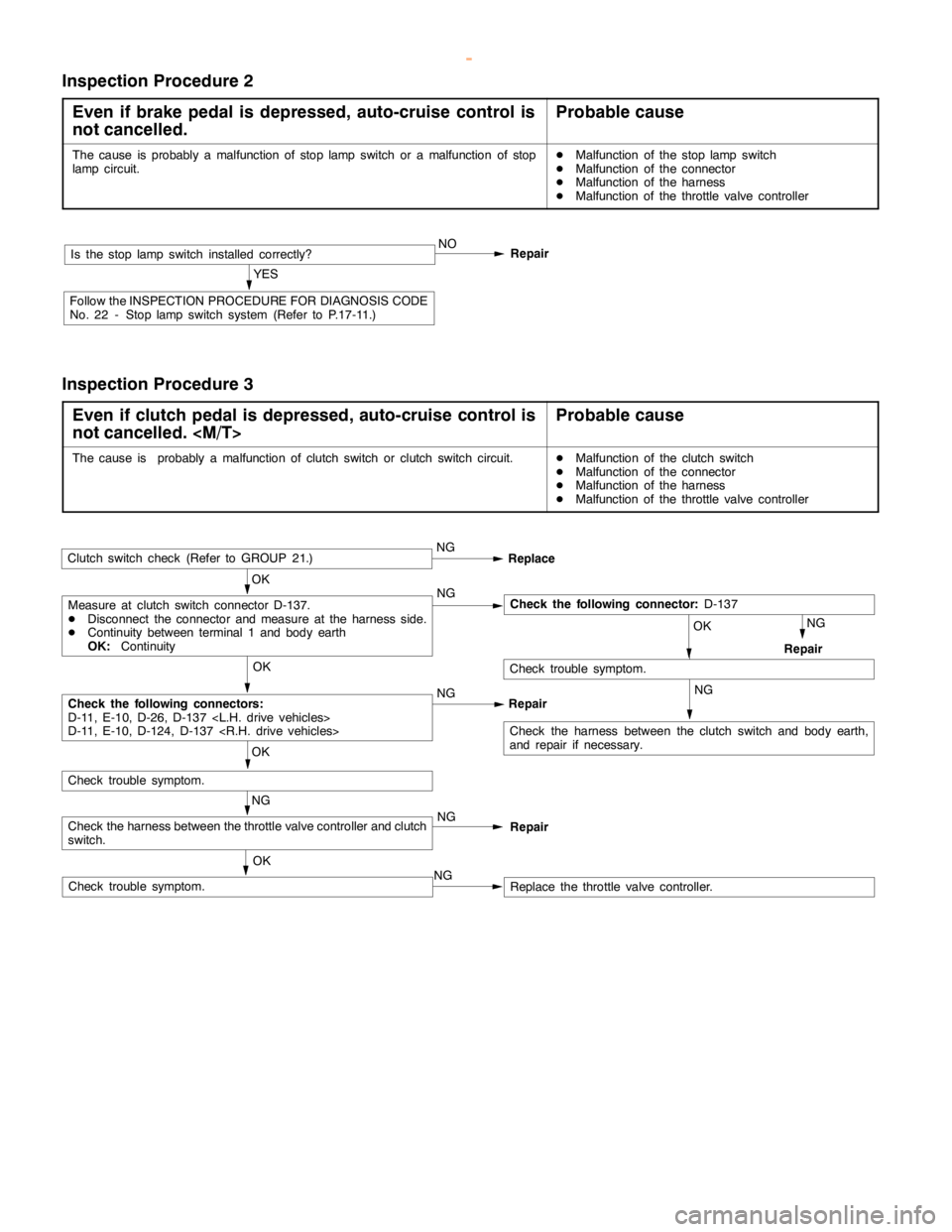
Inspection Procedure 2
Even if brake pedal is depressed, auto-cruise control is
not cancelled.
Probable cause
The cause is probably a malfunction of stoplampswitch or a malfunction of stop
lampcircuit.DMalfunction of the stoplampswitch
DMalfunction of the connector
DMalfunction of the harness
DMalfunction of the throttle valve controller
RepairIs the stoplampswitch installed correctly?NO
YES
Follow the INSPECTIONPROCEDURE FOR DIAGNOSIS CODE
No. 22 - Stoplampswitch system (Refer to P.17-11.)
Inspection Procedure 3
Even if clutch pedal is depressed, auto-cruise control is
not cancelled.
Probable cause
The cause is probably a malfunction of clutch switch or clutch switch circuit.DMalfunction of the clutch switch
DMalfunction of the connector
DMalfunction of the harness
DMalfunction of the throttle valve controller
Clutch switch check (Refer to GROUP 21.)NG
Replace
OK
Measure at clutch switch connector D-137.
DDisconnect the connector and measure at the harness side.
DContinuity between terminal 1 and body earth
OK:ContinuityNGCheck the following connector:D-137
NG
Repair OK
Check trouble symptom.
OK
Check trouble symptom.
OK
Check the following connectors:
D-11, E-10, D-26, D-137
D-11, E-10, D-124, D-137
RepairNG
Check the harness between the clutch switch and body earth,
and repair if necessary.
NG
Check the harness between the throttle valve controller and clutch
switch.
NG
Replace the throttle valve controller. OKCheck trouble symptom.NG
Repair
www.WorkshopManuals.co.uk
Purchased from www.WorkshopManuals.co.uk
Page 822 of 1839
ENGINE AND EMISSION CONTROL -Auto-cruise Control SystemENGINE AND EMISSION CONTROL -Auto-cruise Control System17-20
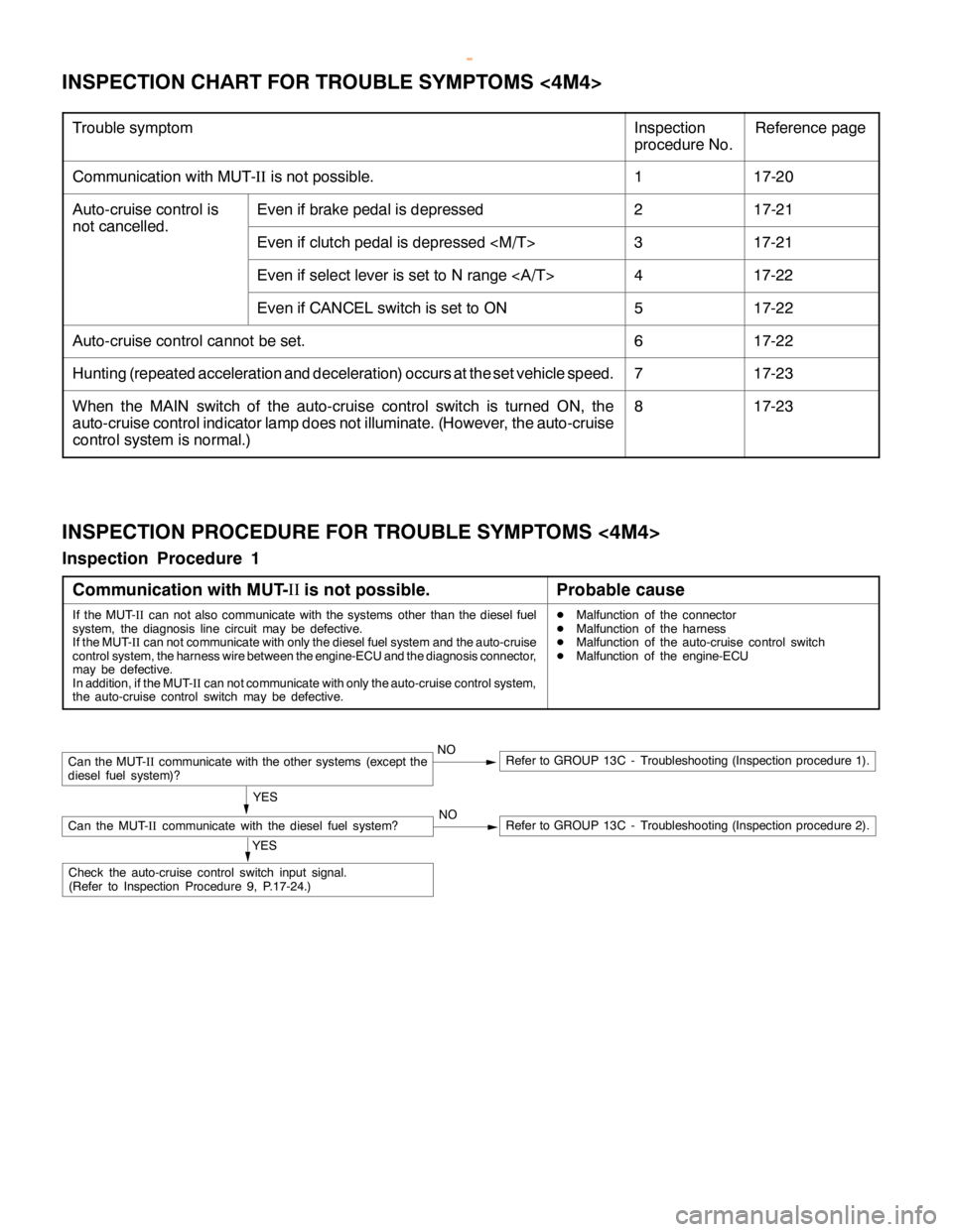
INSPECTION CHART FOR TROUBLE SYMPTOMS <4M4>
Trouble symptomInspection
procedure No.Reference page
Communication with MUT-IIis not possible.117-20
Auto-cruise control isEven if brake pedal is depressed217-21
not cancelled.
Even if clutch pedal is depressed
Even if select lever is set to N range417-22
Even if CANCEL switch is set to ON517-22
Auto-cruise control cannot be set.617-22
Hunting (repeated acceleration and deceleration) occurs at the set vehicle speed.717-23
When the MAIN switch of the auto-cruise control switch is turned ON, the
auto-cruise control indicator lamp does not illuminate. (However, the auto-cruise
control system is normal.)817-23
INSPECTION PROCEDURE FOR TROUBLE SYMPTOMS <4M4>
Inspection Procedure 1
Communication with MUT-II
is not possible.
Probable cause
If the MUT-
IIcan not also communicate with the systems other than the diesel fuel
system, the diagnosis line circuit may be defective.
If the MUT-
IIcan not communicate with only the diesel fuel system and the auto-cruise
control system, the harness wire between the engine-ECU and the diagnosis connector,
may be defective.
In addition, if the MUT-
IIcan not communicate with only the auto-cruise control system,
the auto-cruise control switch may be defective.DMalfunction of the connector
DMalfunction of the harness
DMalfunction of the auto-cruise control switch
DMalfunction of the engine-ECU
NORefer to GROUP 13C - Troubleshooting (Inspection procedure 2).
Can the MUT-
IIcommunicate with the other systems (except the
diesel fuel system)?NORefer to GROUP 13C - Troubleshooting (Inspection procedure 1).
YES
Can the MUT-
IIcommunicate with the diesel fuel system?
YES
Check the auto-cruise control switch input signal.
(Refer to Inspection Procedure 9, P.17-24.)
www.WorkshopManuals.co.uk
Purchased from www.WorkshopManuals.co.uk