2000 MITSUBISHI MONTERO automatic transmission
[x] Cancel search: automatic transmissionPage 981 of 1839
AUTOMATIC TRANSMISSION -Troublehshooting
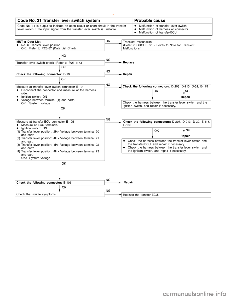
Code No. 31 Transfer lever switch systemProbable cause
Code No. 31 is output to indicate anopencircuit or short-circuit in the transfer
lever switch if the input signal from the transfer lever switch is unstable.DMalfunction of transfer lever switch
DMalfunction of harness or connector
DMalfunction of transfer-ECU
NG
NG
MUT-
IIData List
DNo. 6 Transfer lever position
OK:Refer to P.23-87 (Data List Chart).Transient malfunction
(Refer to GROUP 00 - Points to Note for Transient
Malfunctions.) OK
OK OKOKNG
DCheck the harness between the transfer lever switch and
the transfer-ECU, and repair if necessary.
DCheck the harness between the transfer lever switch and
the ignition switch, and repair if necessary.Repair
Check the harness between the transfer lever switch and the
ignition switch, and repair if necessary.
OK OK
NG
OK
OK
NG
NG
Check the trouble symptoms.Replace the transfer-ECU.
Measure at transfer-ECU connector E-105
DMeasure at ECU terminals.
DIgnition switch: ON
(1) Transfer lever position: 2H> Voltage between terminal 20
and earth
(2) Transfer lever position: 4H> Voltage between terminal 21
and earth
(3) Transfer lever position: 4H> Voltage between terminal 22
and earth
(4) Transfer lever position: 4H> Voltage between terminal 23
and earth
OK:System voltage
Measure at transfer lever switch connector E-19.
DDisconnect the connector and measure at the harness
side.
DIgnition switch: ON
DVoltage between terminal (1) and earth
OK:System voltageNG
Replace
NG
Repair
Transfer lever switch check (Refer to P.23-117.)
Check the following connector:E-19
Repair NG
Check the following connector:E-105Repair
Check the following connectors:D-208, D-213, D-32, E-115,
E-105
Check the following connectors:D-208, D-213, D-32, E-115
www.WorkshopManuals.co.uk
Purchased from www.WorkshopManuals.co.uk
Page 982 of 1839
AUTOMATIC TRANSMISSION -Troublehshooting
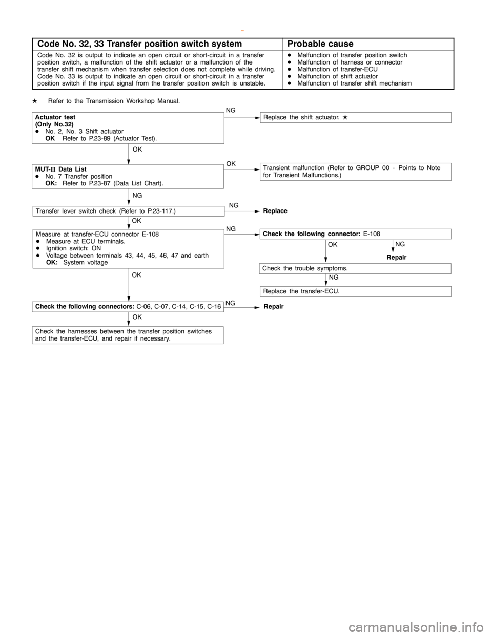
Code No. 32, 33 Transfer position switch systemProbable cause
Code No. 32 is output to indicate anopencircuit or short-circuit in a transfer
position switch, a malfunction of the shift actuator or a malfunction of the
transfer shift mechanism when transfer selection does not complete while driving.
Code No. 33 is output to indicate anopencircuit or short-circuit in a transfer
position switch if the input signal from the transfer position switch is unstable.DMalfunction of transfer position switch
DMalfunction of harness or connector
DMalfunction of transfer-ECU
DMalfunction of shift actuator
DMalfunction of transfer shift mechanism
LRefer to the Transmission Workshop Manual.
OK
Transient malfunction (Refer to GROUP 00 - Points to Note
for Transient Malfunctions.)
OKNG
Check the harnesses between the transfer position switches
and the transfer-ECU, and repair if necessary.OKNG
OK
OK
NG
Replace the transfer-ECU. NG
ReplaceTransfer lever switch check (Refer to P.23-117.)
Repair NG
Repair
Check the trouble symptoms.
NG OK
Replace the shift actuator.
L
MUT-
IIData List
DNo. 7 Transfer position
OK:Refer to P.23-87 (Data List Chart).
NG
Actuator test
(Only No.32)
DNo. 2, No. 3 Shift actuator
OKRefer to P.23-89 (Actuator Test).
Measure at transfer-ECU connector E-108
DMeasure at ECU terminals.
DIgnition switch: ON
DVoltage between terminals 43, 44, 45, 46, 47 and earth
OK:System voltage
Check the following connectors:C-06, C-07, C-14, C-15, C-16
Check the following connector:E-108
www.WorkshopManuals.co.uk
Purchased from www.WorkshopManuals.co.uk
Page 983 of 1839
AUTOMATIC TRANSMISSION -Troublehshooting
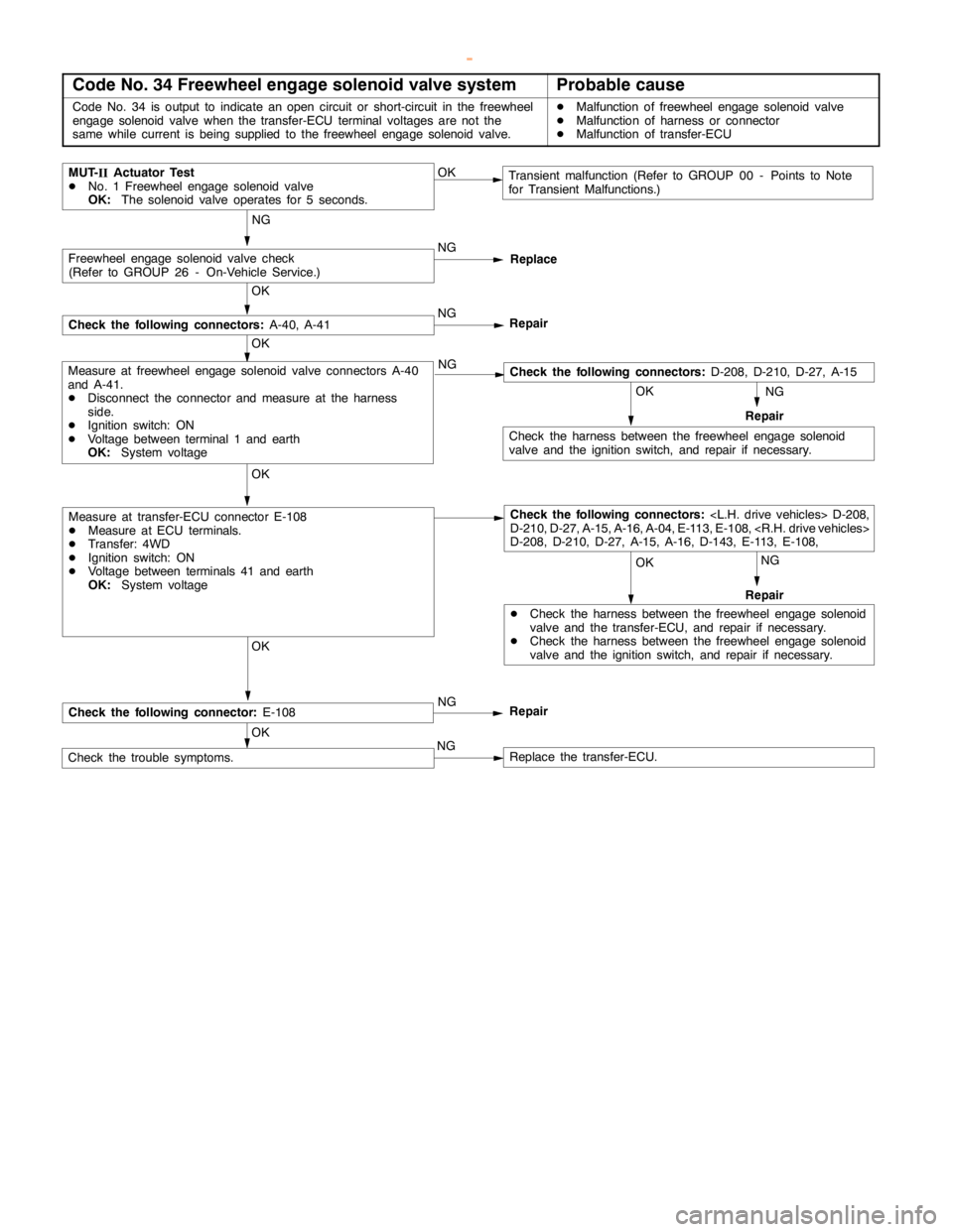
Code No. 34 Freewheel engage solenoid valve systemProbable cause
Code No. 34 is output to indicate anopencircuit or short-circuit in the freewheel
engage solenoidvalve when the transfer-ECU terminal voltages are not the
same while current isbeing supplied to the freewheel engage solenoidvalve.DMalfunction of freewheel engage solenoidvalve
DMalfunction of harness or connector
DMalfunction of transfer-ECU
NG
NG
MUT-
IIActuator Test
DNo. 1 Freewheel engage solenoidvalve
OK:The solenoid valve operates for 5 seconds.Transient malfunction (Refer to GROUP 00 - Points to Note
for Transient Malfunctions.) OK
OK OK OKNG
DCheck the harness between the freewheelengage solenoid
valve and the transfer-ECU, and repair if necessary.
DCheck the harness between the freewheelengage solenoid
valve and the ignition switch, and repair if necessary.Repair
Check the harness between the freewheelengage solenoid
valve and the ignition switch, and repair if necessary.
OK OK
OK
NG
Check the trouble symptoms.Replace the transfer-ECU.
Measure at transfer-ECU connector E-108
DMeasure at ECU terminals.
DTransfer: 4WD
DIgnition switch: ON
DVoltage between terminals 41 and earth
OK:System voltage
Measure at freewheel engage solenoidvalve connectors A-40
and A-41.
DDisconnect the connector and measure at the harness
side.
DIgnition switch: ON
DVoltage between terminal 1 and earth
OK:System voltageNG
Replace
NG
Repair
Freewheel engage solenoidvalve check
(Refer to GROUP 26 - On-Vehicle Service.)
Check the following connectors:A-40, A-41
Repair NG
Check the following connector:E-108
NG
Repair
OK
Check the following connectors:
D-210, D-27, A-15, A-16, A-04, E-113, E-108,
D-208, D-210, D-27, A-15, A-16, D-143, E-113, E-108,
Check the following connectors:D-208, D-210, D-27, A-15
www.WorkshopManuals.co.uk
Purchased from www.WorkshopManuals.co.uk
Page 984 of 1839
AUTOMATIC TRANSMISSION -Troublehshooting
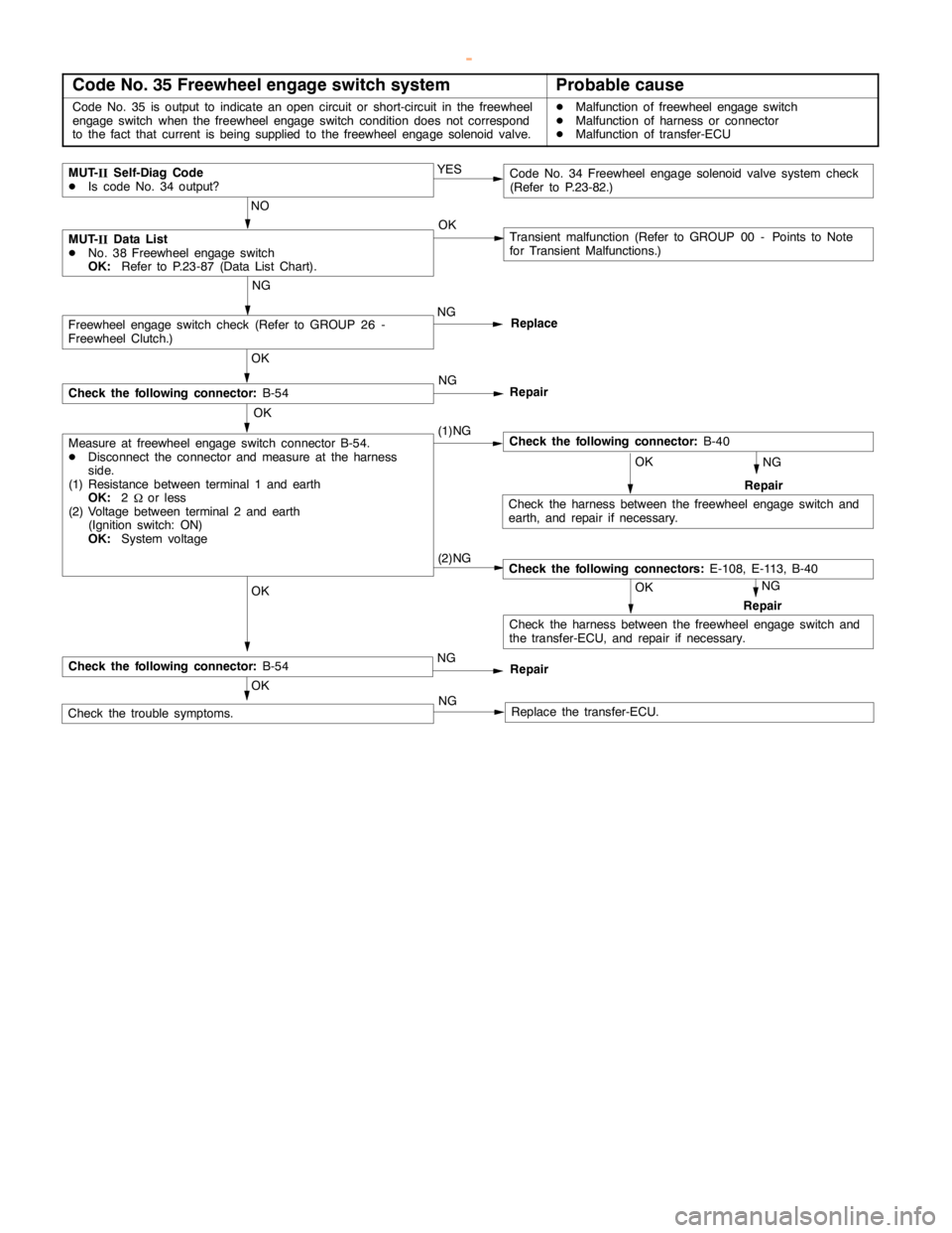
Code No. 35 Freewheel engage switch systemProbable cause
Code No. 35 is output to indicate anopencircuit or short-circuit in the freewheel
engageswitch when the freewheelengageswitch condition does not correspond
to the fact that current isbeing supplied to the freewheel engage solenoidvalve.DMalfunction of freewheel engageswitch
DMalfunction of harness or connector
DMalfunction of transfer-ECU
NG
(1)NG
MUT-
IIData List
DNo. 38 Freewheel engageswitch
OK:Refer to P.23-87 (Data List Chart).Transient malfunction (Refer to GROUP 00 - Points to Note
for Transient Malfunctions.) OK
OK OK OKNG
Repair
Check the following connector:B-40
Check the harness between the freewheelengageswitch and
earth, and repair if necessary.
OK
OK
Check the trouble symptoms.Replace the transfer-ECU.
Measure at freewheel engageswitch connector B-54.
DDisconnect the connector and measure at the harness
side.
(1) Resistance between terminal 1 and earth
OK:2
Wor less
(2) Voltage between terminal 2 and earth
(Ignition switch: ON)
OK:System voltageNG
Replace
NG
Repair
Freewheel engageswitch check (Refer to GROUP 26 -
Freewheel Clutch.)
Check the following connector:B-54
MUT-
IISelf-Diag Code
DIs code No. 34 output?Code No. 34 Freewheelengage solenoidvalve system check
(Refer to P.23-82.) YES
NO
NG
(2)NG
NG
OK
Repair
Check the following connectors:E-108, E-113, B-40
Check the harness between the freewheelengageswitch and
the transfer-ECU, and repair if necessary.
Check the following connector:B-54Repair
NG
www.WorkshopManuals.co.uk
Purchased from www.WorkshopManuals.co.uk
Page 985 of 1839
AUTOMATIC TRANSMISSION -Troublehshooting
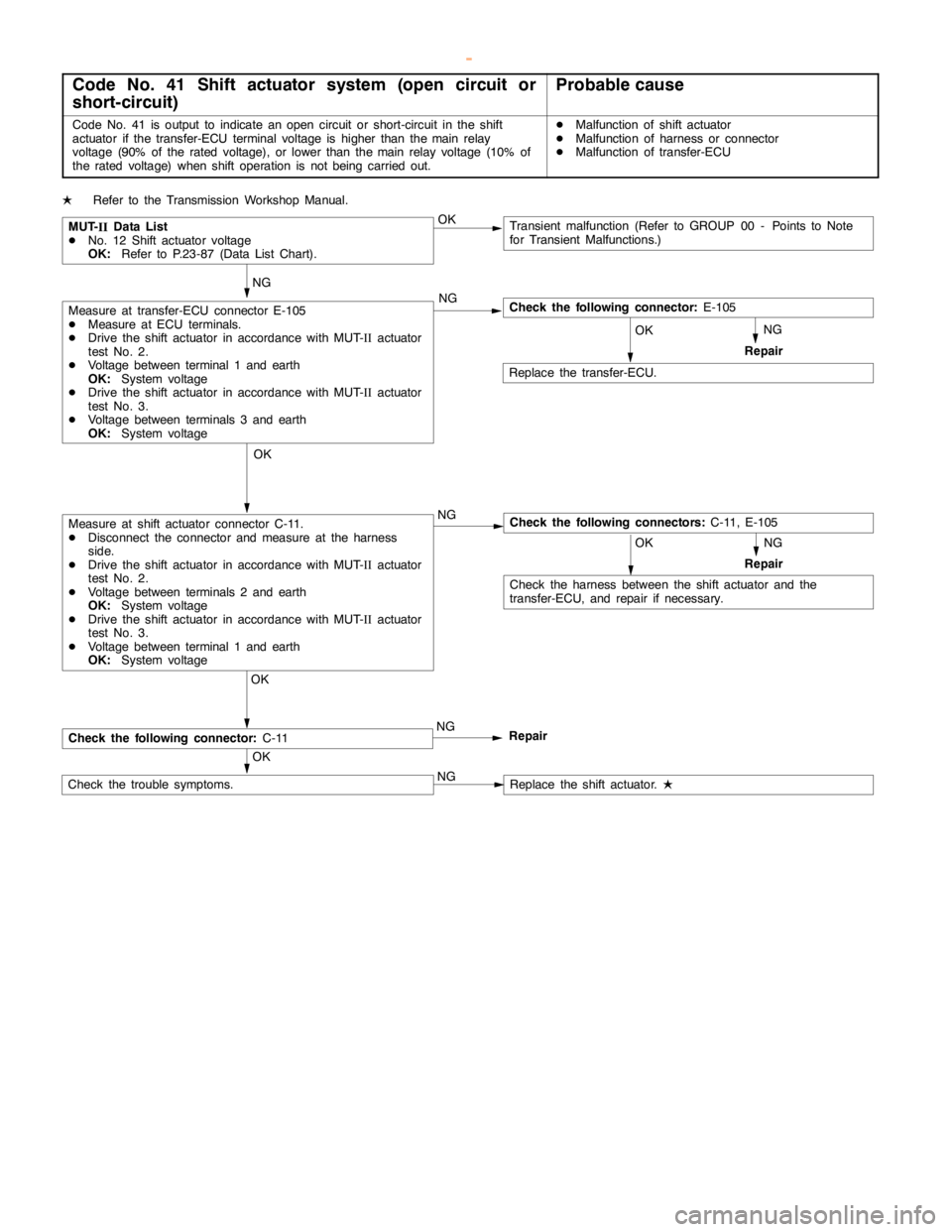
Code No. 41 Shift actuator system (open circuit or
short-circuit)Probable cause
Code No. 41 is output to indicate anopencircuit or short-circuit in the shift
actuator if the transfer-ECU terminal voltage is higher than themainrelay
voltage (90% of the rated voltage), or lower than themainrelay voltage (10% of
the rated voltage) when shift operation is notbeingcarried out.DMalfunction of shift actuator
DMalfunction of harness or connector
DMalfunction of transfer-ECU
LRefer to the Transmission Workshop Manual.
NG
NG
NG
MUT-
IIData List
DNo. 12 Shift actuator voltage
OK:Refer to P.23-87 (Data List Chart).Transient malfunction (Refer to GROUP 00 - Points to Note
for Transient Malfunctions.) OK
OK NG
Check the harness between the shift actuator and the
transfer-ECU, and repair if necessary.Repair
OKOK
OK
OK
NG
NG
Replace the transfer-ECU.
Check the following connectors:C-11, E-105Measure at shift actuator connector C-11.
DDisconnect the connector and measure at the harness
side.
DDrive the shift actuator in accordance with MUT-
IIactuator
test No. 2.
DVoltage between terminals 2 and earth
OK:System voltage
DDrive the shift actuator in accordance with MUT-
IIactuator
test No. 3.
DVoltage between terminal 1 and earth
OK:System voltage
Measure at transfer-ECU connector E-105
DMeasure at ECU terminals.
DDrive the shift actuator in accordance with MUT-
IIactuator
test No. 2.
DVoltage between terminal 1 and earth
OK:System voltage
DDrive the shift actuator in accordance with MUT-
IIactuator
test No. 3.
DVoltage between terminals 3 and earth
OK:System voltage
Repair NG
Check the following connector:C-11Repair
Replace the shift actuator.
L
Check the following connector:E-105
Check the trouble symptoms.
www.WorkshopManuals.co.uk
Purchased from www.WorkshopManuals.co.uk
Page 986 of 1839
AUTOMATIC TRANSMISSION -Troublehshooting
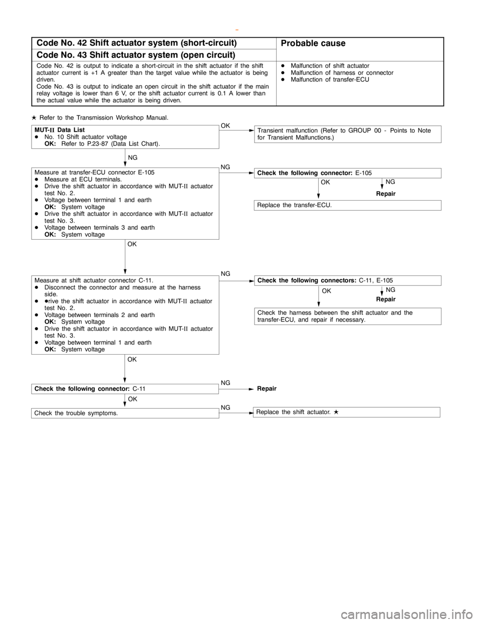
Code No. 42 Shift actuator system (short-circuit)Probable cause
Code No. 43 Shift actuator system (open circuit)
Code No. 42 is output to indicate a short-circuit in the shift actuator if the shift
actuator current is +1 A greater than the target value while the actuator isbeing
driven.
Code No. 43 is output to indicate anopencircuit in the shift actuator if themain
relay voltage is lower than 6 V, or the shift actuator current is 0.1 A lower than
the actual value while the actuator isbeing driven.DMalfunction of shift actuator
DMalfunction of harness or connector
DMalfunction of transfer-ECU
LRefer to the Transmission Workshop Manual.
NG
NG
MUT-
IIData List
DNo. 10 Shift actuator voltage
OK:Refer to P.23-87 (Data List Chart).Transient malfunction (Refer to GROUP 00 - Points to Note
for Transient Malfunctions.) OK
OK NG
Check the harness between the shift actuator and the
transfer-ECU, and repair if necessary.Repair
Check the following connector:E-105
OK OK
NG
OK
OK
NG
NG
Check the trouble symptoms.
Replace the transfer-ECU.
Check the following connectors:C-11, E-105Measure at shift actuator connector C-11.
DDisconnect the connector and measure at the harness
side.
DDrive the shift actuator in accordance with MUT-
IIactuator
test No. 2.
DVoltage between terminals 2 and earth
OK:System voltage
DDrive the shift actuator in accordance with MUT-
IIactuator
test No. 3.
DVoltage between terminal 1 and earth
OK:System voltage
Measure at transfer-ECU connector E-105
DMeasure at ECU terminals.
DDrive the shift actuator in accordance with MUT-
IIactuator
test No. 2.
DVoltage between terminal 1 and earth
OK:System voltage
DDrive the shift actuator in accordance with MUT-
IIactuator
test No. 3.
DVoltage between terminals 3 and earth
OK:System voltage
Repair NG
Check the following connector:C-11Repair
Replace the shift actuator.
L
www.WorkshopManuals.co.uk
Purchased from www.WorkshopManuals.co.uk
Page 987 of 1839
AUTOMATIC TRANSMISSION -Troublehshooting
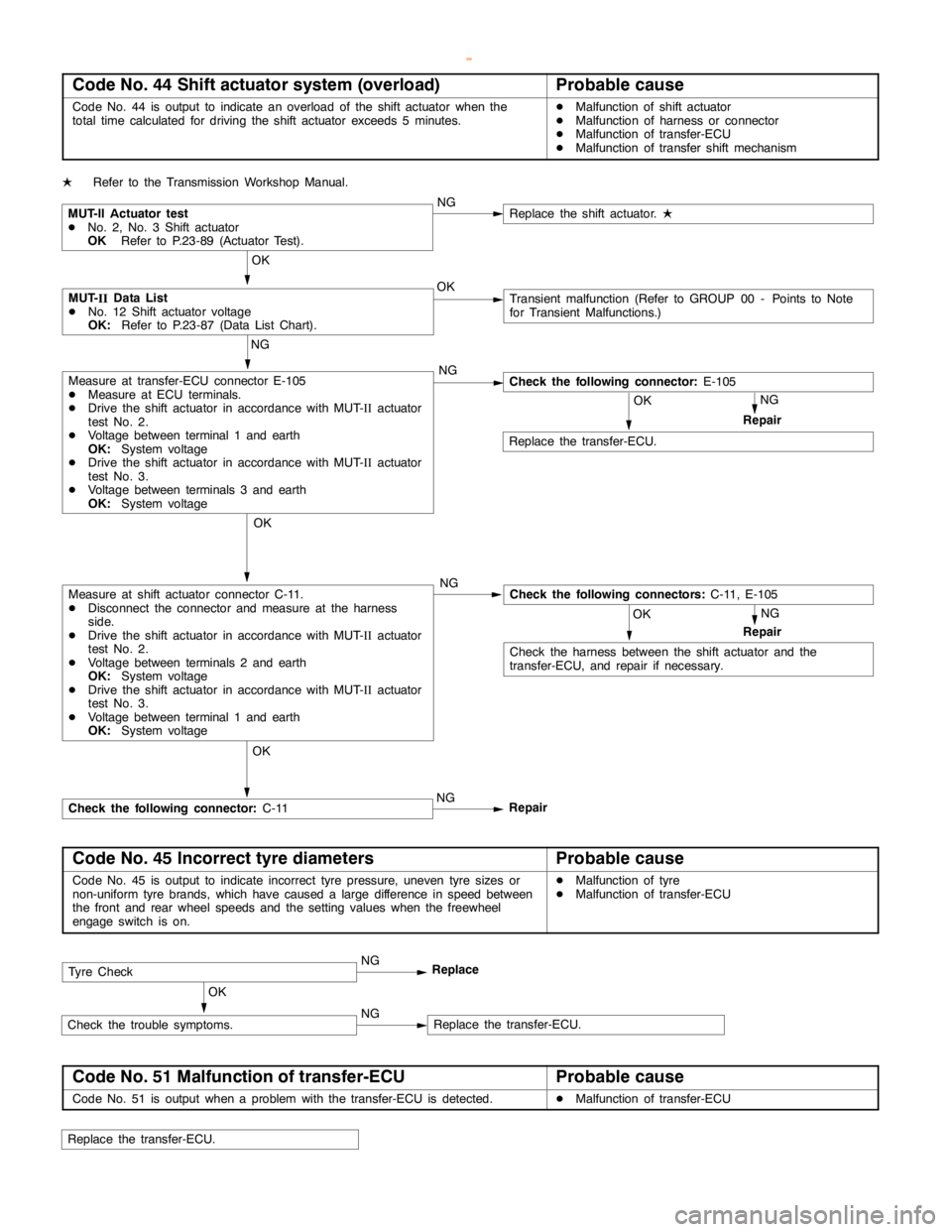
Code No. 44 Shift actuator system (overload)Probable cause
Code No. 44 is output to indicate an overload of the shift actuator when the
total time calculated for driving the shift actuator exceeds 5 minutes.DMalfunction of shift actuator
DMalfunction of harness or connector
DMalfunction of transfer-ECU
DMalfunction of transfer shift mechanism
LRefer to the Transmission Workshop Manual.
NG
NG
MUT-
IIData List
DNo. 12 Shift actuator voltage
OK:Refer to P.23-87 (Data List Chart).Transient malfunction (Refer to GROUP 00 - Points to Note
for Transient Malfunctions.) OK
OK NG
Check the harness between the shift actuator and the
transfer-ECU, and repair if necessary.Repair
Check the following connector:E-105
OK
NG
OK
OK
NG
Replace the transfer-ECU.
Check the following connectors:C-11, E-105Measure at shift actuator connector C-11.
DDisconnect the connector and measure at the harness
side.
DDrive the shift actuator in accordance with MUT-
IIactuator
test No. 2.
DVoltage between terminals 2 and earth
OK:System voltage
DDrive the shift actuator in accordance with MUT-
IIactuator
test No. 3.
DVoltage between terminal 1 and earth
OK:System voltage
Measure at transfer-ECU connector E-105
DMeasure at ECU terminals.
DDrive the shift actuator in accordance with MUT-
IIactuator
test No. 2.
DVoltage between terminal 1 and earth
OK:System voltage
DDrive the shift actuator in accordance with MUT-
IIactuator
test No. 3.
DVoltage between terminals 3 and earth
OK:System voltage
Repair NG
Check the following connector:C-11Repair
MUT-II Actuator test
DNo. 2, No. 3 Shift actuator
OKRefer to P.23-89 (Actuator Test).
OKNGReplace the shift actuator.
L
Code No. 45 Incorrect tyre diametersProbable cause
Code No. 45 is output to indicate incorrect tyre pressure, uneven tyre sizes or
non-uniform tyre brands, which have caused a large difference in speed between
the front and rear wheel speeds and the setting values when the freewheel
engageswitch is on.DMalfunction of tyre
DMalfunction of transfer-ECU
NG
Replace
Replace the transfer-ECU. NGCheck the trouble symptoms.
OK
Tyre Check
Code No. 51 Malfunction of transfer-ECUProbable cause
Code No. 51 is output when a problem with the transfer-ECU is detected.DMalfunction of transfer-ECU
Replace the transfer-ECU.
www.WorkshopManuals.co.uk
Purchased from www.WorkshopManuals.co.uk
Page 988 of 1839

AUTOMATIC TRANSMISSION -Troubleshooting
DATA LIST REFERENCE TABLE
Item
No.Check itemInspection conditionsNormal condition
1Accelerator pedalEngine: StoppedAccelerator pedal: Fully closed985 - 1,085 mV
position sensor
(APS)Selector lever position:
PAccelerator pedal: DepressedGradually increases from
the above value.
Accelerator pedal: Fully open4000 mV or higher
2Front propeller shaft
speed sensorTransfer position: 4WDDriving at a constant speed of
30 km/h30 km/h
3Rear propeller shaftTransfer position: 4WDDriving at a constant speed of30 km/h3Rear propeller shaft
speed sensorTransfer position: 4WDDriving at a constant speed of
30 km/h30 km/h
4Difference between
front and rear pro-
peller shaft speedsTransfer position: 4WDDriving at a constant speed of
30 km/hWithin 5 km/h
5Vehicle speedIdling in 1st (Vehicle stopped)0 km/h
Driving at a constant speed of 50 km/h in 3rd50 km/h
6Transfer lever posi-Ignition switch: ONTransfer shift lever position: 2H2H
tionEngine: StoppedTransfer shift lever position: 4H4H
Transfer shift lever position:
4HLc4HLc
Transfer shift lever position:
4LLc4LLc
7Transfer positionDriving at a constant
speed of 10 km/hTransfer shift lever position:
2H®4H2H - 4H®4H
Transfer shift lever position:
4H®4HLc4H - 4HL®4HL
Engine: Stopped
Selector lever position:Transfer shift lever position:
4HLc®4LLc4HL - 4LL®4LL
NTransfer shift lever position:
4LLc®4HLc4HL - 4LL®4HL
Driving at a constant
speed of 10 km/hTransfer shift lever position:
4HLc®4H4H - 4HL®4H
Transfer shift lever position:
4H®2H2H - 4H®2H
8Main relay voltageIgnition switch: ONSystem voltage (V)
9Ignition voltageIgnition switch: ONSystem voltage (V)
10Shift actuator cur-
rentDuring transfer selection (while motor is running)0A®0.2 A®0A
11Target currentDuring transfer selection (while motor is running)0A®1.5 A®0A
12Shift actuator volt-
ageIgnition switch: ON
Selector lever position: N
Transfer shift lever position: 2H®4H (or 4H®4HLc,
4HLc®4LLc)System voltage (V)
Ignition switch: ON
Selector lever position: N
Transfer shift lever position: 4LLc®4HLc (or 4HLc®4H,
4H®2H)System voltage (V)
www.WorkshopManuals.co.uk
Purchased from www.WorkshopManuals.co.uk