Page 926 of 1111
SR0E3±03
F02565
± STEERINGPOWER STEERING GEAR
SR±45
2215 Author�: Date�:
2000 LEXUS GS300/GS400 (RM718U)
REMOVAL
NOTICE:
Remove the steering wheel assembly before the steering
gear removal, because there is possibility of breaking of
the spiral cable.
1. PLACE FRONT WHEELS FACING STRAIGHT AHEAD
2. REMOVE STEERING WHEEL PAD
(See page SR±11)
3. REMOVE STEERING WHEEL
(See page SR±11)
4. DISCONNECT RH AND LH TIE ROD ENDS
(See page SA±9)
5. DISCONNECT INTERMEDIATE SHAFT ASSEMBLY
(See page SR±11)
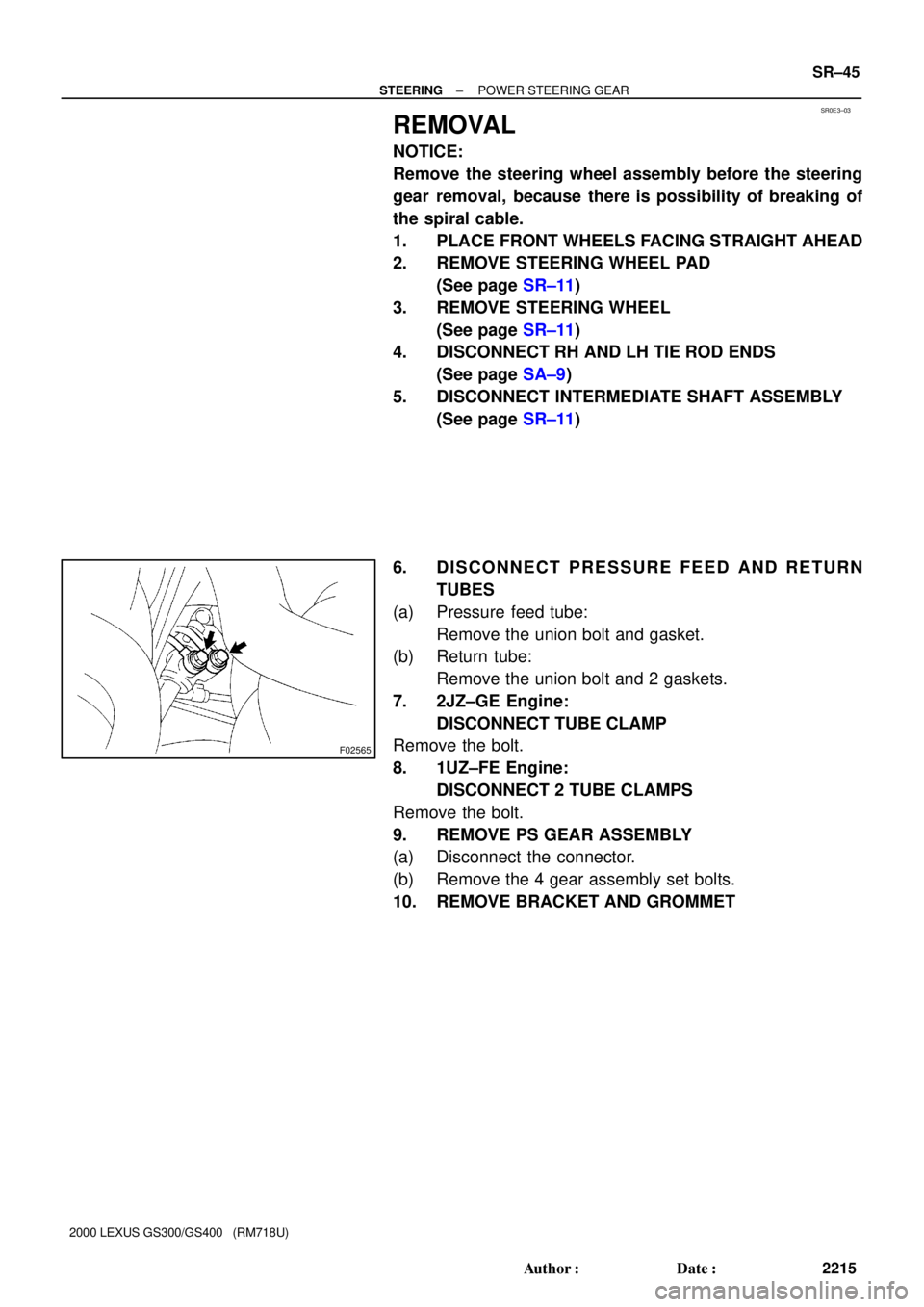
6. DISCONNECT PRESSURE FEED AND RETURN
TUBES
(a) Pressure feed tube:
Remove the union bolt and gasket.
(b) Return tube:
Remove the union bolt and 2 gaskets.
7. 2JZ±GE Engine:
DISCONNECT TUBE CLAMP
Remove the bolt.
8. 1UZ±FE Engine:
DISCONNECT 2 TUBE CLAMPS
Remove the bolt.
9. REMOVE PS GEAR ASSEMBLY
(a) Disconnect the connector.
(b) Remove the 4 gear assembly set bolts.
10. REMOVE BRACKET AND GROMMET
Page 938 of 1111

INSTALLATION
1. INSTALL GROMMET AND BRACKET
2. INSTALL PS GEAR ASSEMBLY
(a) Torque the 4 g")
SR0E7±01
F02565
± STEERINGPOWER STEERING GEAR
SR±57
2227 Author�: Date�:
2000 LEXUS GS300/GS400 (RM718U)
INSTALLATION
1. INSTALL GROMMET AND BRACKET
2. INSTALL PS GEAR ASSEMBLY
(a) Torque the 4 gear assembly set bolts.
Torque: 65 N´m (660 kgf´cm, 48 ft´lbf)
(b) Connect the connector.
3. 2JZ±GE Engine:
CONNECT TUBE CLAMP
Torque the bolt.
Torque: 5 N´m (55 kgf´cm, 48 in.´lbf)
4. 1UZ±FE Engine:
CONNECT 2 TUBE CLAMPS
Torque the bolt.
Torque: 5 N´m (55 kgf´cm, 48 in.´lbf)
5. CONNECT INTERMEDIATE SHAFT ASSEMBLY
(See page SR±17)
6. CONNECT PRESSURE FEED AND RETURN TUBES
(a) Pressure feed tube:
Torque the union bolt over a new gaskets.
Torque: 42 N´m (430 kgf´cm, 31 ft´lbf)
(b) Return tube:
Torque the union bolt with a new gasket on each side of
the tube.
Torque: 42 N´m (430 kgf´cm, 31 ft´lbf)
7. CONNECT RH AND LH TIE ROD ENDS
(See page SA±9)
8. POSITION FRONT WHEELS FACING STRAIGHT
AHEAD
HINT:
Do it with the front of the vehicle jacked up.
9. CENTER SPIRAL CABLE
(See page SR±17)
10. INSTALL STEERING WHEEL
(a) Align the matchmarks on the wheel and steering column
main shaft.
(b) Temporarily tighten the wheel set nut.
(c) Connect the connector.
11. BLEED POWER STEERING SYSTEM
(See page SR±3)
12. CHECK STEERING WHEEL CENTER POINT
13. TORQUE STEERING WHEEL SET NUT
Torque: 35 N´m (360 kgf´cm, 26 ft´lbf)
14. INSTALL STEERING WHEEL PAD
(See page SR±17)
15. CHECK FRONT WHEEL ALIGNMENT
(See page SA±4)
Page 940 of 1111
F04512
2JZ±GE:
1UZ±FE:
Vacuum Hose
Vacuum Hose
SR0DI±01
± STEERINGAIR CONTROL VALVE
SR±7
2177 Author�: Date�:
2000 LEXUS GS300/GS400 (RM718U)
AIR CONTROL VALVE
INSPECTION
1. TURN AIR CONDITIONING SWITCH OFF
2. CHECK IDLE±UP
(a) Start the engine and run it at idle.
(b) Fully turn the steering wheel.
(c) Check that the engine rpm decreases when the vacuum
hose of the air control valve is pinched.
(d) Check that the engine rpm increases when the hose is re-
leased.
Page 941 of 1111

STEERING WHEEL
INSP")
F02558
SR0DJ±01
F02559
F03673
PPS Solenoid
Connector
2JZ±GE:
1UZ±FE:PPS Solenoid
Connector
SR±8
± STEERINGSTEERING WHEEL
2178 Author�: Date�:
2000 LEXUS GS300/GS400 (RM718U)
STEERING WHEEL
INSPECTION
1. CHECK STEERING WHEEL FREEPLAY
With the vehicle stopped and tires pointed straight ahead, rock
the steering wheel gently back and forth with light finger pres-
sure.
Freeplay should not exceed the maximum.
Maximum freeplay: 30 mm (1.18 in.)
2. CHECK STEERING EFFORT
(a) Center the steering wheel.
(b) Remove the steering wheel pad. (See page SR±11)
(c) Start the engine and run it at idle.
(d) Measure the steering effort in both directions.
Reference: 7 N´m (70 kgf´cm, 61 in.´lbf)
HINT:
Be sure to consider the tire type, pressure and contact surface
before making your diagnosis.
(e) Disconnect the PPS solenoid connector.
(f) Measure the steering effort in both directions and check
that the steering effort exceeds the reference value in (d),
and that the power assist is operating. If steering effort is
not heavier than (d), check the solenoid.
HINT:
Take the tire type, pressure and contact surface into consider-
ation before making your diagnosis.
(g) Connect the connector.
(h) Torque the steering wheel set nut.
Torque: 35 N´m (360 kgf´cm, 26 ft´lbf)
(i) Install the steering wheel pad.
(See page SR±17)
Page 1000 of 1111
RS07U±01
H02618
2JZ±GE Engine:
Air Cleaner Assembly
1UZ±FE Engine:
Air Cleaner AssemblyAir Cleaner Inlet No.1
ECU Box Upper Cover
ECU Box Front Airbag
Sensor RH
Front Airbag Sensor LH
7.8 (80, 69 in.´lbf)
7.8 (80, 69 in.´lbf)
: Specified torqueN´m (kgf´cm, ft´lbf)
� Non±reusable part�
�
± SUPPLEMENTAL RESTRAINT SYSTEMFRONT AIRBAG SENSOR
RS±57
2288 Author�: Date�:
2000 LEXUS GS300/GS400 (RM718U)
FRONT AIRBAG SENSOR
COMPONENTS
Page 1002 of 1111
H02698
H02702
H02699
H02697
± SUPPLEMENTAL RESTRAINT SYSTEMFRONT AIRBAG SENSOR
RS±59
2290 Author�: Date�:
2000 LEXUS GS300/GS400 (RM718U)
2. REMOVE RH FRONT AIRBAG SENSOR
(a) Remove the bolt and No.1 air cleaner inlet.
(b) 2JZ±GE Engine:
Disconnect the connector and inlet hose, then remove the
3 bolts and air cleaner.
(c) 1UZ±FE Engine:
Disconnect the connector and inlet hose, then remove the
3 bolts and air cleaner.
(d) Disconnect the connector, then remove the bolt, nut and
sensor.
Page 1041 of 1111
SA0RM±01
F02337
HID Type Headlight:
Height Control Sensor LinkPS Gear
Assembly
Pressure Feed
and Return Tubes
Shock Absorber
Bracket
No.2 Lower Suspension Arm
Strut Bar Bracket
Brake Caliper
Stabilizer Bar Link No.1 Lower Suspension
Arm
Engine Under CoverDisc Clip
� Gasket
5.4 (55, 48 in.´lbf)
59 (600, 44)
118 (1,200, 87)
: Specified torque
� Non±reusable partN´m (kgf´cm, ft´lbf)
87 (890, 64)
172 (1,755, 127)
� Cotter Pin55 (560, 43)
164 (1,690, 122)
162 (1,650, 119)
58 (590, 43)
152 (1,550, 112)
113 (1,150, 83)
35 (360, 26)
65 (660, 48)
Engine Under Cover
Rear RH
Engine Under Cover
Rear LH
157 (1,600, 116)
± SUSPENSION AND AXLEFRONT LOWER SUSPENSION ARM
SA±29
2029 Author�: Date�:
2000 LEXUS GS300/GS400 (RM718U)
FRONT LOWER SUSPENSION ARM
COMPONENTS
Page 1042 of 1111

REMOVAL
1. REMOVE FRONT WHEEL
Torque: 103 N´m")
SA0RN±01
F02311
F02312
SST
F02317
F02318
SA±30
± SUSPENSION AND AXLEFRONT LOWER SUSPENSION ARM
2030 Author�: Date�:
2000 LEXUS GS300/GS400 (RM718U)
REMOVAL
1. REMOVE FRONT WHEEL
Torque: 103 N´m (1,050 kgf´cm, 76 ft´lbf)
2. REMOVE ENGINE UNDER COVERS
3. REMOVE BRAKE CALIPER
(a) Remove the 2 bolts and caliper.
Torque: 118 N´m (1,200 kgf´cm, 87 ft´lbf)
(b) Support the brake caliper securely.
(c) Remove the disc.
4. DISCONNECT TIE ROD END
(a) Remove the clip and nut.
Torque: 87 N´m (890 kgf´cm, 64 ft´lbf)
(b) Using SST, disconnect the tie rod end from the steering
knuckle.
SST 09610±20012
5. HID TYPE HEADLIGHT:
DISCONNECT HEIGHT CONTROL SENSOR LINK
FROM SHOCK ABSORBER BRACKET
Remove the nut and disconnect the height control sensor link
from the shock absorber bracket.
Torque: 5.4 N´m (55 kgf´cm, 48 in.´lbf)
6. REMOVE STABILIZER BAR LINK
(a) Remove the bolt and nut, disconnect the stabilizer bar link
from the stabilizer bar.
Torque: 55 N´m (560 kgf´cm, 43 ft´lbf)
(b) Remove the nut and stabilizer bar link.
Torque: 113 N´m (1,150 kgf´cm, 83 ft´lbf)