Page 941 of 1111

STEERING WHEEL
INSP")
F02558
SR0DJ±01
F02559
F03673
PPS Solenoid
Connector
2JZ±GE:
1UZ±FE:PPS Solenoid
Connector
SR±8
± STEERINGSTEERING WHEEL
2178 Author�: Date�:
2000 LEXUS GS300/GS400 (RM718U)
STEERING WHEEL
INSPECTION
1. CHECK STEERING WHEEL FREEPLAY
With the vehicle stopped and tires pointed straight ahead, rock
the steering wheel gently back and forth with light finger pres-
sure.
Freeplay should not exceed the maximum.
Maximum freeplay: 30 mm (1.18 in.)
2. CHECK STEERING EFFORT
(a) Center the steering wheel.
(b) Remove the steering wheel pad. (See page SR±11)
(c) Start the engine and run it at idle.
(d) Measure the steering effort in both directions.
Reference: 7 N´m (70 kgf´cm, 61 in.´lbf)
HINT:
Be sure to consider the tire type, pressure and contact surface
before making your diagnosis.
(e) Disconnect the PPS solenoid connector.
(f) Measure the steering effort in both directions and check
that the steering effort exceeds the reference value in (d),
and that the power assist is operating. If steering effort is
not heavier than (d), check the solenoid.
HINT:
Take the tire type, pressure and contact surface into consider-
ation before making your diagnosis.
(g) Connect the connector.
(h) Torque the steering wheel set nut.
Torque: 35 N´m (360 kgf´cm, 26 ft´lbf)
(i) Install the steering wheel pad.
(See page SR±17)
Page 942 of 1111
SR0DK±03
F03671
Column Upper CoverCombination Switch
(w/ Spiral Cable)Steering Wheel Lower
No.2 CoverTorx Screw
Steering Wheel Pad
Steering Wheel
Steering Wheel Lower No.3
Cover
Finish Plate Steering Column
Assembly
Column Lower Cover
8.8 (90, 78 in.´lbf)
Torx Screw
8.8 (90, 78 in.´lbf)
35 (360, 26)
25 (260, 19)
End Pad
No.1 Safety
Pad Brake Pedal
Return Spring
Dust Cover
Intermediate Shaft
Assembly
Heater to Register Dust No.7
OBD II
No.1 Under CoverHood Lock Release
Lever
N´m (kgf´cm, ft´lbf) : Specified torque
35 (360, 26)
± STEERINGPOWER TILT AND POWER TELESCOPIC STEERING
COLUMNSR±9
2179 Author�: Date�:
2000 LEXUS GS300/GS400 (RM718U)
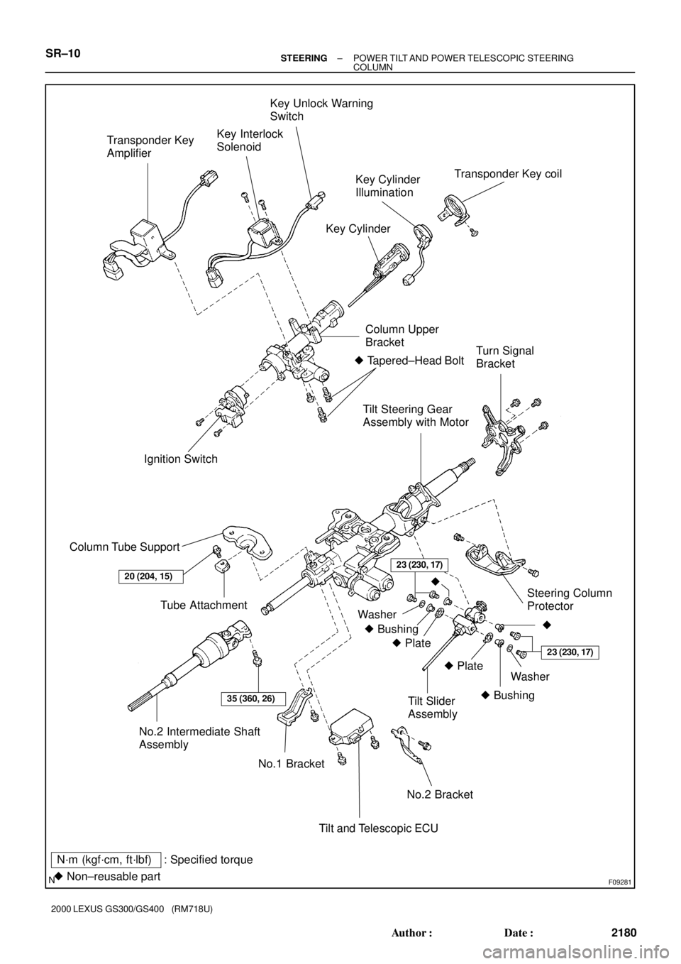
POWER TILT AND POWER TELESCOPIC STEERING
COLUMN
COMPONENTS
Page 943 of 1111
F09281
No.2 Intermediate Shaft
Assembly
Tilt and Telescopic ECUNo.2 BracketSteering Column
Protector
No.1 Bracket Column Tube SupportIgnition Switch� Tapered±Head Bolt
Tilt Steering Gear
Assembly with MotorTurn Signal
Bracket Key Interlock
SolenoidKey Unlock Warning
Switch
Key Cylinder
Illumination
Key Cylinder
35 (360, 26)
N´m (kgf´cm, ft´lbf) : Specified torque
� Non±reusable part
20 (204, 15)
Tube Attachment
Column Upper
BracketTransponder Key coil
Transponder Key
Amplifier
� Plate
Tilt Slider
Assembly23 (230, 17)
�
� Bushing�
23 (230, 17)
� Plate
� Bushing
Washer
Washer
SR±10± STEERINGPOWER TILT AND POWER TELESCOPIC STEERING
COLUMN
2180 Author�: Date�:
2000 LEXUS GS300/GS400 (RM718U)
Page 945 of 1111
RS087±02
H03719
Column Upper Cover
Spiral Cable
Column Lower CoverSteering Wheel
Steering Wheel Pad
35 (360, 26)
8.8 (90, 78 in.´lbf)
: Specified torqueN´m (kgf´cm, ft´lbf)
± SUPPLEMENTAL RESTRAINT SYSTEMSTEERING WHEEL PAD AND SPIRAL CABLE
RS±13
2244 Author�: Date�:
2000 LEXUS GS300/GS400 (RM718U)
STEERING WHEEL PAD AND SPIRAL CABLE
COMPONENTS
Page 970 of 1111
RS07D±01
H02588
Instrument Panel
Front Passenger
Airbag Assembly
5.6 (57, 49 in.´lbf)
: Specified torqueN´m (kgf´cm, ft´lbf)
± SUPPLEMENTAL RESTRAINT SYSTEMFRONT PASSENGER AIRBAG ASSEMBLY
RS±27
2258 Author�: Date�:
2000 LEXUS GS300/GS400 (RM718U)
FRONT PASSENGER AIRBAG ASSEMBLY
COMPONENTS
Page 981 of 1111

INSTALLATION
NOTICE:
Never use airbag parts")
RS07I±01
H02591
H02590
H04226
RS±38
± SUPPLEMENTAL RESTRAINT SYSTEMFRONT PASSENGER AIRBAG ASSEMBLY
2269 Author�: Date�:
2000 LEXUS GS300/GS400 (RM718U)
INSTALLATION
NOTICE:
Never use airbag parts from another vehicle. When replac-
ing parts, replace with new parts.
1. INSTALL FRONT PASSENGER AIRBAG ASSEMBLY
(a) Install the front passenger airbag assembly with 2 nuts.
Torque: 5.6 N´m ( 57 kgf´cm, 49 in.´lbf)
NOTICE:
�Pass the straps of the front passenger airbag door
through the brackets on the right and left sides se-
curely.
�Install the straps so that they are not pinched be-
tween the airbag and instrument panel.
(b) Install the 2 straps and 2 bolts.
NOTICE:
�When installing the front passenger airbag assembly,
make sure that the straps are not distorted and
installed to the brackets securely.
�Make sure that the front passenger airbag assembly
is installed to the specified torque.
�If the front passenger airbag assembly has been
dropped, or there are cracks, dents or other defects
in the case or connector, replace the front passenger
airbag assembly with a new one.
�When installing the front passenger airbag assembly,
take care that the wiring does not interfere with other
parts and is not pinched between other parts.
2. INSTALL INSTRUMENT PANEL
(See page BO±97)
Install the 2 bolts to the instrument panel reinforcement.
Torque: 20 N´m (205 kgf´cm, 15 ft´lbf)
3. CONNECT AIRBAG CONNECTOR
(a) Connect the airbag connector.
(b) Install the airbag connector to glove compartment door
finish plate.
(c) Install the glove compartment door finish plate.
Page 982 of 1111
RS07J±02
H11866
Seatback CoverFront Seatback Board
Seat Cushion Assembly
Seat Adjuster
Front Seat Inner
Cushion Cover
Seat Track CoverSeat Track Cover
Reclining Adjuster
Inside Cover LH
Front Seat Cushion ShieldFront Seat Outer Belt
Seat Belt Anchor
Cover Cap Power Seat
Switch KnobSide Airbag Assembly
: Specified torque
N´m (kgf´cm, ft´lbf)
� Non±reusable part� Hog Ring
61 (622, 45)
61 (622, 45)
19 (194, 14)
37 (375, 27)
37 (375, 27)
42 (430, 31)
37 (375, 27)37 (375, 27)
19 (194, 14)
19 (194, 14)
Headrest Support Headrest
± SUPPLEMENTAL RESTRAINT SYSTEMSIDE AIRBAG ASSEMBLY
RS±39
2270 Author�: Date�:
2000 LEXUS GS300/GS400 (RM718U)
SIDE AIRBAG ASSEMBLY
COMPONENTS
Page 993 of 1111

INSTALLATION
NOTICE:
Never use airbag parts from another vehi")
RS0JE±01
H02863
H02864
RS±50
± SUPPLEMENTAL RESTRAINT SYSTEMSIDE AIRBAG ASSEMBLY
2281 Author�: Date�:
2000 LEXUS GS300/GS400 (RM718U)
INSTALLATION
NOTICE:
Never use airbag parts from another vehicle. When replac-
ing parts, replace them with new parts.
1. INSTALL SEATBACK ASSEMBLY
(a) Install the wire harness to the seat cushion inside covers
as shown in the illustration.
NOTICE:
Be careful not to damage the wire harness.
(b) Install the seat cushion inside cover with the 2 screws.
HINT:
Do the same for LH and RH.
(c) Install the seatback assembly with the 4 bolts.
Torque: 61 N´m (622 kgf´cm, 45 ft´lbf)
(d) Install new hog rings.
HINT:
When installing hog rings, take care to prevent wrinkles as least
as possible.
(e) Install the seatback board with the 2 screws to the seat-
back assembly.
2. INSTALL SEAT CUSHION ASSEMBLY
(a) Install the seat cushion assembly with the 4 bolts to the
seat adjuster.
(b) Install the wire harness to the seat cushion, as shown in
the illustration.
Torque: 19 N´m (194 kgf´cm, 14 ft´lbf)
3. INSTALL FRONT SEAT INNER CUSHION COVER
4. INSTALL FRONT SEAT CUSHION SHIELD
5. INSTALL NO.1 FRONT SEAT CUSHION SHIELD
6. INSTALL POWER SEAT SWITCH KNOBS
7. INSTALL HEADREST
8. INSTALL FRONT SEAT
(a) Mount the front seat to the vehicle.
(b) Connect the connectors.
(c) Slide the front seat to the rearmost position.
(d) Tighten the bolts on the rear side temporarily,from the bolt
on the outer side tighten them completely.
Torque: 37 N´m (375 kgf´cm, 27 ft´lbf)
(e) Slide the front seat to the most front position.
(f) Tighten the bolts on the rear side temporarily, from the bolt
on the outer side tighten them completely.
Torque: 37 N´m (375 kgf´cm, 27 ft´lbf)
(g) Install the 4 seat track covers.
Steering Wheel Lower
No.2 CoverTorx Screw
Steering Wheel Pad
Steering Wheel
Steering Wheel Lower No.3
Cover
Finish Plate Steering")

8.8 (90, 78 in.´lbf)
: Specified torqueN´m (kgf´cm, ft´lbf)
± SUPPLEMENTAL RESTRA")

: Specified torqueN´m (kgf´cm, ft´lbf)
± SUPPLEMENTAL RESTRAINT SYSTEMFRONT PASSENGER AIRBAG ASSEMBLY
RS±27")
