Page 880 of 1111
SF0N3±02
B01873
Rear Seat Cushion
Floor Service Hole Cover
Fuel Pump & Sender Gauge
Connector
Fuel Tank Vent Tube
Set PlateFuel Tank Main Tube
Tube Joint Clip
Fuel Pump and Sender Gauge
Assembly
Fuel Sub Suction Hose
� Non±reusable part
� Gasket
x 8
N´m (kgf´cm, ft´lbf): Specified torque
3.5 (36, 31 in.´lbf)
± SFI (2JZ±GE)FUEL PUMP
SF±9
1475 Author�: Date�:
2000 LEXUS GS300/GS400 (RM718U)
COMPONENTS
Page 885 of 1111
 =Ram diameter (cm)
100 kgf
2x 3.14 (p)
2
(psi) =Ram diameter (in.)
221 lbf
2x 3.14 (p)
2
(kPa) = (kgf/cm2) x 98.1
(kPa) = (psi) x 6.9
B01975")
B01974
40 mm
Contact
Plate
20 mm37 mmWooden
Block
(kgf/cm2) =Ram diameter (cm)
100 kgf
2x 3.14 (p)
2
(psi) =Ram diameter (in.)
221 lbf
2x 3.14 (p)
2
(kPa) = (kgf/cm2) x 98.1
(kPa) = (psi) x 6.9
B01975
SST
ST±12
± STARTING (2JZ±GE)STARTER
1630 Author�: Date�:
2000 LEXUS GS300/GS400 (RM718U)
(f) Temporarily tighten the terminal nuts.
(g) Tighten the terminal nut
(1) Put a wooden block on the contact plate and press
it down with a hand press.
Dimensions of wooden block:
20 x 37 x 40 mm (0.79 x 1.46 x 1.57 in.)
Press force:
981 N (100 kgf, 221 lbf)
NOTICE:
�Check the diameter of the hand press ram. Then
calculate the gauge pressure of the press when
981 N (100 kgf, 221 lbf) of force is applied.
Gauge pressure:
�If the contact plate is not pressed down with the spe-
cified pressure, the contact plate may tilt due to coil
deformation or the tightening of the nut.
(2) Using SST, tighten the nuts to the specified torque.
SST 09810±38140
Torque: 17 N´m (173 kgf´cm, 13 ft´lbf)
NOTICE:
If the nut is over tightened, it may cause cracks on the in-
side of the insulator.
Page 886 of 1111
B01972
± STARTING (2JZ±GE)STARTER
ST±13
1631 Author�: Date�:
2000 LEXUS GS300/GS400 (RM718U)
(h) Clean the contact surfaces of the remaining contact plate
and plunger with a dry shop rag.
(i) Reinstall the plunger, new gasket, end cover and lead
clamp with the 3 bolts.
Torque: 2.5 N´m (26 kgf´cm, 22 in.´lbf)
Page 892 of 1111
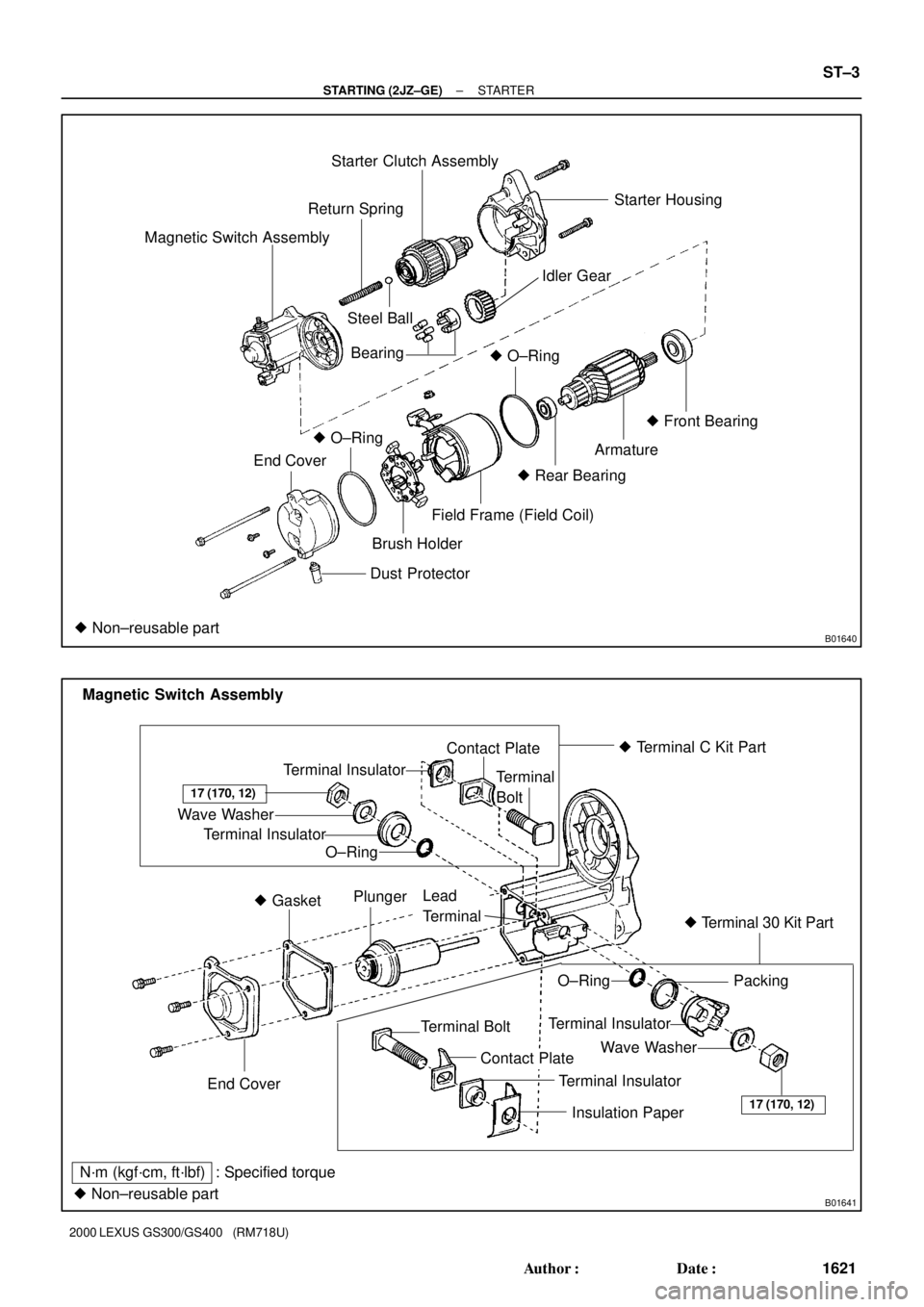
B01640
Starter Clutch Assembly
Magnetic Switch AssemblyReturn SpringStarter Housing
Idler Gear
Steel Ball
� O±Ring
Armature� Front Bearing
� Rear Bearing
Field Frame (Field Coil)
Dust Protector
� Non±reusable part
Brush Holder
� O±Ring
End CoverBearing
B01641
� Terminal C Kit Part
� Terminal 30 Kit Part
� Non±reusable partTerminal Insulator
Wave Washer
Terminal Insulator
O±RingContact Plate
Terminal
Bolt
17 (170, 12)
End Cover� GasketPlunger
Lead
Terminal
O±RingPacking
Terminal Insulator
Wave Washer
17 (170, 12)
Terminal Bolt
Contact Plate
Terminal Insulator
Insulation Paper
N´m (kgf´cm, ft´lbf) : Specified torqueMagnetic Switch Assembly
± STARTING (2JZ±GE)STARTER
ST±3
1621 Author�: Date�:
2000 LEXUS GS300/GS400 (RM718U)
Page 893 of 1111
ST04Z±01
B01960
B01981
Clamp
Bracket
ST±4
± STARTING (2JZ±GE)STARTER
1622 Author�: Date�:
2000 LEXUS GS300/GS400 (RM718U)
REMOVAL
REMOVE STARTER
(a) Remove the rubber cap and nut, and disconnect the start-
er wire.
(b) Disconnect the starter connector.
(c) Remove the 2 bolts and starter.
Torque: 37 N´m (380 kgf´cm, 27 ft´lbf)
HINT:
At time of the installation, place refer to the following item.
When installing the upper bolt, tighten it together with the clamp
bracket.
Page 894 of 1111

(2)(3)(4)
(5)
ST0948
Magnetic Finger
± STARTING (2JZ±GE)STARTER
ST±5
1623 Author�: Date�:
2000 LEXUS GS300/GS400 (RM718U)
DISASSEMBLY
DISASSEMBLY
1. REMO")
ST050±01
B02814
B01647
B01959
B01970
(1)
(2)(3)(4)
(5)
ST0948
Magnetic Finger
± STARTING (2JZ±GE)STARTER
ST±5
1623 Author�: Date�:
2000 LEXUS GS300/GS400 (RM718U)
DISASSEMBLY
DISASSEMBLY
1. REMOVE DUST PROTECTOR
2. REMOVE FIELD FRAME AND ARMATURE
(a) Remove the nut, and disconnect the lead wire from the
magnetic switch terminal.
Torque: 5.9 N´m (60 kgf´cm, 52 in.´lbf)
(b) Remove the 2 through bolts.
Torque: 5.9 N´m (60 kgf´cm, 52 in.´lbf)
(c) Pull out the field frame together with the armature.
HINT:
Align the protrusion of the field frame with the groove of the
magnetic switch.
(d) Remove the O±ring from the field frame.
HINT:
At the time of installation, please refer to the following items.
Use a new O±ring.
3. REMOVE STARTER HOUSING, CLUTCH ASSEMBLY
AND GEAR
(a) Remove the 2 bolts.
Torque: 5.9 N´m (60 kgf´cm, 52 in.´lbf)
(b) Remove these parts from the magnetic switch:
(1) Starter housing
(2) Return spring
(3) Idler gear
(4) Bearing
(5) Clutch assembly
4. REMOVE STEEL BALL
Using a magnetic finger, remove the steel ball from the clutch
shaft hole.
Page 895 of 1111
B01645
P10568
ST±6
± STARTING (2JZ±GE)STARTER
1624 Author�: Date�:
2000 LEXUS GS300/GS400 (RM718U)
5. REMOVE BRUSH HOLDER
(a) Remove the 2 screws and end cover from the field frame.
Torque: 1.5 N´m (15 kgf´cm, 13 in.´lbf)
(b) Remove the O±ring from the field frame.
HINT:
At the time of installation, please refer to the following items.
Use a new O±ring.
(c) Using a screwdriver, hold the spring back and disconnect
the brush from the brush holder. Disconnect the 4
brushes, and remove the brush holder.
NOTICE:
Check that the positive (+) lead wires are not grounded.
6. REMOVE ARMATURE FROM FIELD FRAME
Page 904 of 1111

REASSEMBLY
NOTICE:
When using a vise, do not overtighten it.
1")
SR0X1±01
F09385
± STEERINGPOWER TILT AND POWER TELESCOPIC STEERING
COLUMNSR±15
2185 Author�: Date�:
2000 LEXUS GS300/GS400 (RM718U)
REASSEMBLY
NOTICE:
When using a vise, do not overtighten it.
1. INSTALL TILT AND TELESCOPIC ECU
Install the tilt and telescopic ECU with the 2 screws.
2. INSTALL NO.2 BRACKET
Install the No.2 bracket with the bolt.
3. INSTALL NO.1 BRACKET
Install the No.1 bracket with the bolt.
4. INSTALL TILT SLIDER ASSEMBLY
(a) Install 2 new plates and 4 new bushings to the tilt slider
assembly in the direction shown in the illustration.
HINT:
Install the bushings with their cuts facing downward.
(b) Using a hexagon wrench, install the tilt slider assembly
with the 2 washers and 4 bolts.
Torque: 23 N´m (230 kgf´cm, 17 ft´lbf)
HINT:
�When replacing a tilt slider assembly with new one, apply
grease on the removed tilt slider assembly to the shaft of
the new tilt slider assembly.
�Install the tilt slider assembly with the bolt portion of the
tilt slider faced downward.
�Do not let the grease be stuck on the thread part of the bolt
in order to prevent the bolt from slipping.
5. INSTALL STEERING COLUMN PROTECTOR
Install the steering column protector.
6. INSTALL TURN SIGNAL BRACKET
Install the turn signal bracket with the 3 bolts.
7. INSTALL COLUMN TUBE SUPPORT
NOTICE:
If the attachment or support is deformed, replace it with a
new one.
(a) Install the tube attachment to the tube support.
(b) Install the column tube support with the bolt.
Torque: 20 N´m (204 kgf´cm, 15 ft´lbf)
NOTICE:
Make sure to install the support facing the correct direction
(See page SR±9).
�Tighten the bolt while holding the support to prevent
it turning too.
�Be sure to tighten the bolt with the specified torque.