2000 HONDA CR-V Filter air
[x] Cancel search: Filter airPage 215 of 1395
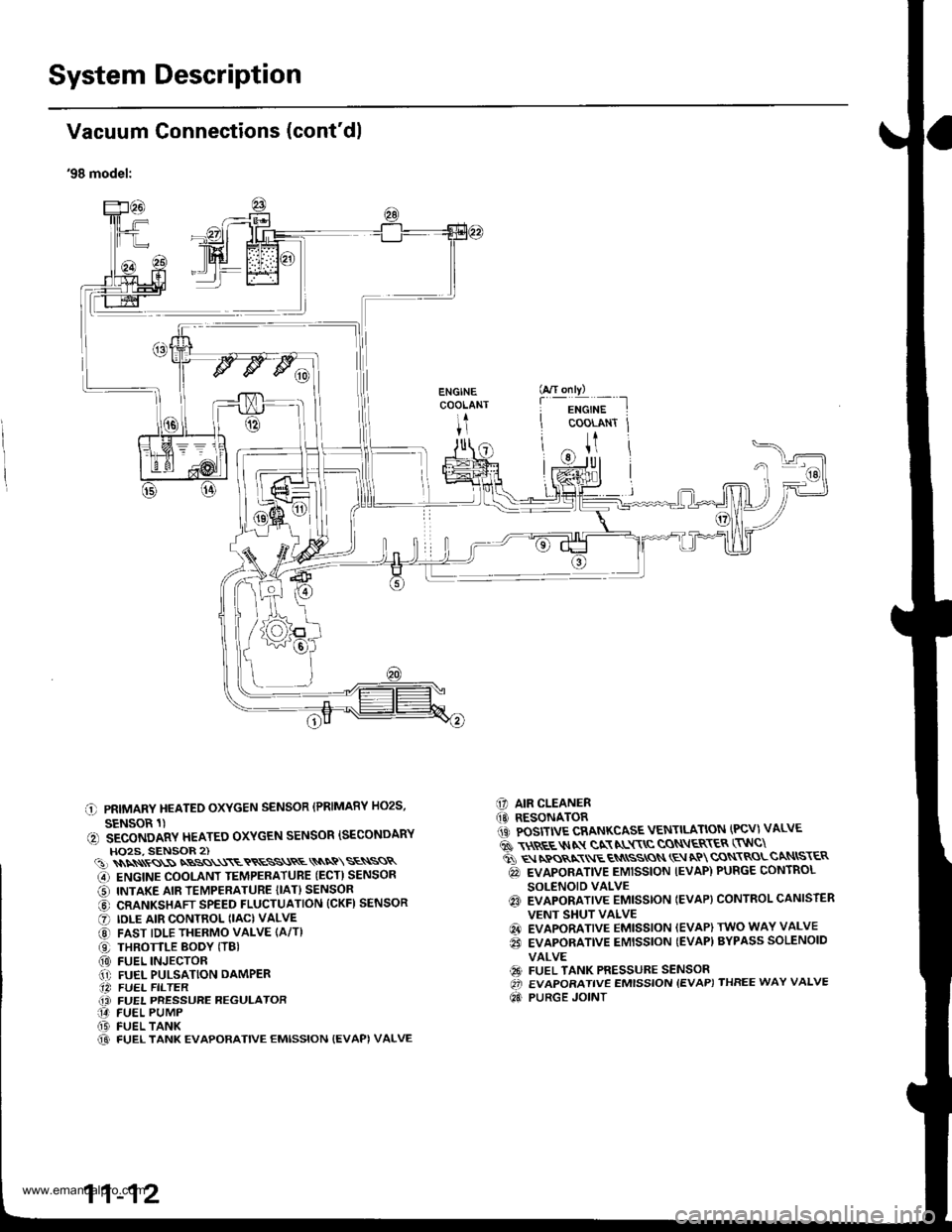
System Description
I
I
I
Vacuum Connections (cont'dl
'98 model:
C PRIMARY HEATEO OXYGEN SENSOR (PRIMARY HO2S,
SENSOR 1)(, SECONDARY HEATEO OXYGEN SENSOR ISECONDARYHO2S, SENSOR 2)(!)\\\\ss\SNBSS\\\ETRESS\RE\\NQ\SE\SSR
G) ENGINE COOLANT TEMPERATUBE (ECT) SENSOR
O INTAKE AIR TEMPERATURE {IAT} SENSOR
@ CRANKSHAFT SPEED FLUCTUATION (CKFI SENSOR
O IDLE AIR CONTROL (IAC) VALVE
@ FAST IDLE THERMO VALVE (A/T)
O THROTTLE BODY (TBI(0) FUEL INJECTOR.1' FUEL PULSATION DAMPER.14 FUEL FILTER(i FUEL PRESSURE REGULATOR14 FUEL PUMP(D FUEL TANK@ FUEL TANK EVAPORATIVE EMISSION {EVAPI VALVE
C] AIR CLEANER(O RESONATOR1iC POSITIVE CRANKCASE VENTILATION (PCV) VALVE
6 \$REE$IN gN NL$\C CON\ER\ER (TNC\
ti q rpos,xr E qN
ssros \E aP cqN\RoLcaNtsr€R
@ EVAPORATIVE EMISSION IEVAP) PURGE CONTROL
SOLENOID VALVEq3 EVAPORATIVE EMISSTON IEVAP} CONTROL CANISTER
VENT SHUT VALVE
@ EVAPORATIVE EMISSION (EVAP) TWO WAY VALVE
€i EVAPORATIVE EMISSION {EVAP) BYPASS SOLENOID
VALVE
€9 FUEL TANK PRESSURE SENSOROi EVAPORATIVE EMISSION {EVAP) THREE WAY VALVE
Qd PURGE JOINT
G/T only)
f
-i*'";-t
COOLANT Jt
U
11-12
www.emanualpro.com
Page 217 of 1395
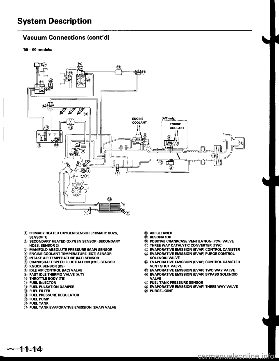
System Description
Vacuum Connections (cont'dl
'99 - q) models:
ENGINECOOLANT
t
o
o
o@
o@@@@@@@@@(t
PRIMARY HEATED OXYGEN SENSOR IPRIMARY HO2S,SENSOR 1lSECONDARY HEATED OXYGEN SENSOR {SECONDARYHO2S. SENSOR 2lMANIFOLD ABSOLUTE PRESSURE (MAPI SENSORENGINE COOLANT TEMPERATURE IECN SENSORINTAKE AIR TEMPERATURE IIATI SENSORCRANKSHAFT SPEED FLUCTUATION {CKF) SENSORKNOCK SENSOR (KS}
IDLE AIR CONTROL IIACI VALVEFAST IDLE THERMO VALVE {A/T}THROTTLE BODY (TB}
FUEL INJECTORFUEL PULSATION DAMPERFUEL FILTERFUEL PRESSURE REGULATORFUEL PUMPFUEL TANKFUEL TANK EVAPORATIVE EMISSION (EVAPI VALVE
AIR CLEANERRESONATORPOSITIVE CRANKCASE VENTILATION (PCV} VALVETHREE WAY CATALYTIC CONVERTER ITWCIEVAPORATIVE EMISSION {EVAPI CONTROL CANISTEREVAPORATIVE EMISSION IEVAPI PURGE CONTROLSOLENOID VALVEEVAPORATIVE EMISSION {EVAPI CONTROL CANISTEFVENT SHUT VALVEEVAPORATIVE EMISSION IEVAPI TWO WAY VALVEEVAPONANVE EMISSION {EVAPI AYPASS SOLENOIDVALVEFUEL TANK PRESSURE SENSOBEVAPORATIVE EMISSION IEVAPI THREE WAY VALVEPURGE JOINT
@@@@@@
@
@@
@@@
11-14
www.emanualpro.com
Page 326 of 1395
PGM-FI System
Fuel Supply System
[POliil The"""ntool indicates Diagnostic Troubte Code (DTC) p0'171:Thefuet system istoo lean.
[Fo17ZJ rh""""ntool indicates Diagnostic Troubte code {DTc) p0172:Thefuel svstem istoorich.
Description
By monitoring the Long Term Fuel rrim, long term malfunctions in the fuel system will be detected.lf a malfunction has been detected during two consecutive trips, the MIL will come on and DTc p0171 and/or pol72 will bestored.
NOTE: lf someof the DTCS listed below are stored atthesametimeas DTC P017'l and/or p0172, troubleshoot those DTcsfirst, then troubleshoot DTC P0171 and/or PO1i2.
P0107, P0108, P1128, P'1129: MAP Sensor
P0135: Primary HO2S (Sensor 1)Heater
P0137, P0138: Secondary HO2S {Sensor 2)P0141: Secondary H02S (Sensor 2) Heater
P0441*r: EVAP System lnsufficient Purge FtowP1456*,, P'l457 *?i EVAP System Insufficient purge Ftow
Possible Cause
DTC P0171
too lean
*1: '97 model*2: '98 - 00 models
Fuel Pump insufficient flow/pressure
Fuel Feed Line clogged. leaking
Fuel Pressure Regulator stuck openFuel Filter clogged
Fuel Injector clogged, air leakage
Gasoline doesn't meet Owner's Manual spec.Primary HO2S (Sensor 1) deteriorated
Valve Clearance
Exhaust leak
Fuel Pressure Regulator clogged, stuck closedFuel Return Pipe clogged
Fuel Injector leaking
Gasoline doesn't meet Owner's Manual spec.Primary H02S (Sensor 1) deteriorated
EVAP Purge Control Solenoid Valve leaking, stuck openedValve Clearance
DTC P0172
flch
11-124
www.emanualpro.com
Page 781 of 1395
17.Make sure the transmission is in E position.
Fill the transmission with ATF, and run the engine
for 30 seconds or until approximately 0.951 {1.0 US
qt., 0.8 lmp qt.) is discharged.
Remove the drain hose, and reconnect the cooler
return hose to the transmission (see page 14-266).
Refill the transmission with ATF to the proper level
(see page l4'161 ).
18.
19.
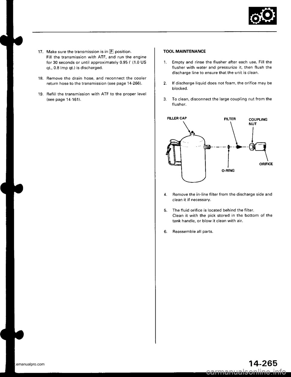
TOOL MAINTENANCE
1. €mpty and rinse the flusher after each use. Fill the
flusher with water and pressurize it, then flush the
discharge line to ensure that the unit is clean.
2. lf discharge liquid does not foam, the orifice may be
blocked.
3. To clean, disconnect the large coupling nut from the
flusher.
FILTER
\-0--D
I
IO.RING
Remove the in-line filter from the discharge side and
clean it if necessary.
The fluid orifice is located behind the filter.
Clean it with the pick stored in the bottom of the
tank handle, or blow it clean with air.
Reassemble all parts.
COUPLINGNUT
II
-@q
\ORIFICE
4.
5.
6.
FILLER CAP
14-265
www.emanualpro.com
Page 1091 of 1395
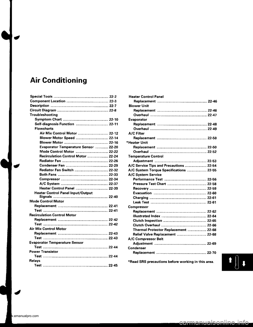
Air Conditioning
Heater Control Panel
Reofacement ,.,...,,.,..,.,.,,22-46
Blower Unit
Replacement .................. 22-46
Overhaul ...........,,,., .......-.22-17
Evaporalor
ReDlacement ...,.,.,..,......,22-4A
Overhaul ................ .........22-19
A/C Filter
Replacement ..................22-50*Heater Unit
ReDfacement ..................22-50
Overhaul ..,.,..,.,...,.. .........22-52
Temperature Control
Adiustment ....................22-53
A/C Service Tips and Precauiions............-....-.... 22-54
A/C System Torque Specifications .................... 22-55
A/C System Service
Performance Test ......,...22-56
Pressure Test Chart .-.....22-5a
Recovery ..............,. ...-.-...22-59
Evacuation -...........-........22-60
Charging ................ .......-.22-61
Leak Test ........................22-61
Compressor
Repfacement ..........-.......22-62
flfustrated Index .....,.......22-64
Cfutch fnspection .........,.22-65
Cfutch Overhaul ............- 22-66
Thermaf Protector Rep|acement ................... 22-68
Refief Valve Replacement .............................. 22-68
A/C Comoressor Belt
Adiustment .................... 22-69
Condenser
Repfacement .,.....,,.,..,.,..22-70
'Read SRS precautions betore working in this area.
www.emanualpro.com
Page 1139 of 1395
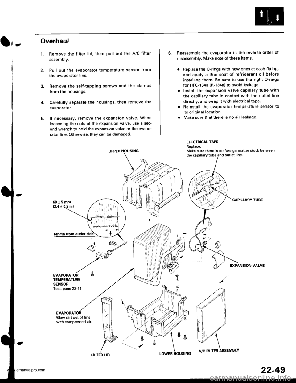
}-Overhaul
1. Remove the filter lid. then pull out the A/C filter
assembly.
Pull out the evaporator temperature sensor from
the evaporator fins.
Remove the self-tapping screws and the clamps
from the housings.
Carefully separate the housings, then remove the
evaporator.
lf necessary, remove the expansion valve When
loosening the nuts of the expansion valve, use a sec-
ond wrench to hold the expansion valve or the evapo-
rator line. Otherwise, they can be damaged.
6. Reassemble the evaporator in the reverse order of
disassembly. Make note of these items.
. Replace the O-rings with new ones at each fitting,
and apply a thin coat of refrigerant oil before
installing them. Be sure to use the right O-rings
for HFC-'134a (R-134a) to avoid leakage.
. Install the expansion valve capillary tube with
the capillary tube in contact with the outlet line
directly, and wrap it with electricaltape.
. Reinstall the evaporator temperature sensor to
its original location.
. Make sure that there is no air leakage.
ELECTRICAL TAPEReplace.Make sure there is no foreign matter stuck between
the capillary tube and outlet line.
CAPILLARY TUAE
EXPANSION VALVE
4.
TEMPERATURESENSORlest, page 22-41
,m
\!{
YFILTER LID
;
I-OWER HOUSINGA/C FILTER ASSEMBLY
22-49
www.emanualpro.com
Page 1140 of 1395
A/C FilterHeater Unit
Replacement
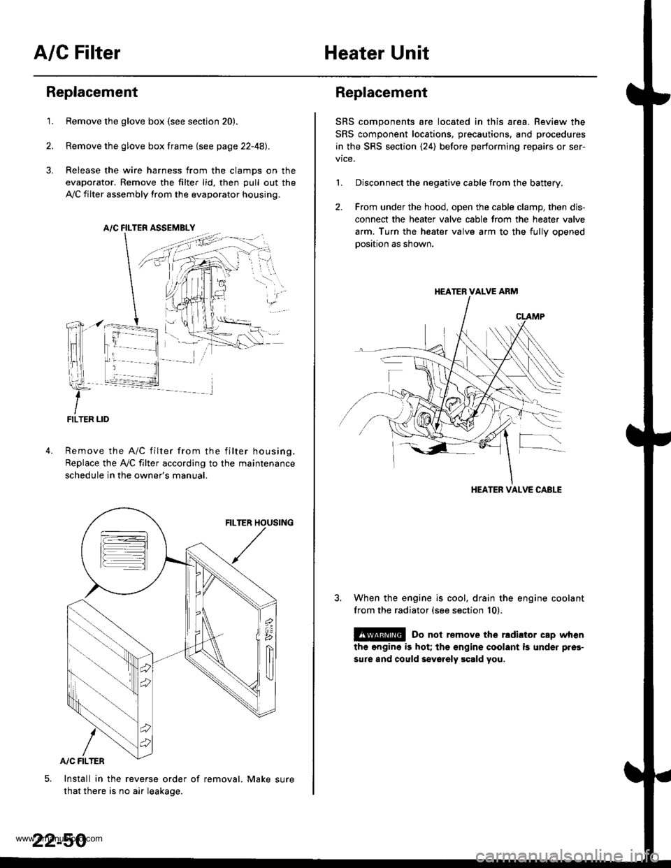
1.Remove the glove box (see section 20).
Remove the glove box frame {see page 22-4A).
Release the wire harness from the clamps on the
evaporator. Remove the filter lid, then pull out the
,VC filter assembly from the evaporator housing.
A/C FILTER ASSEMELY
Remove the A/C filter from the filter housing.
Replace the Ay'C filter according to the maintenance
schedule in the owner's manual.
Install in the reverse order of removal. Make sure
that there is no air leakage.
22-50
Replacement
SRS components are located in this area. Review the
SRS component locations, precautions, and procedures
in the SRS section {24) before performing repairs or ser-
1. Disconnect the negative cable from the battery.
2. From under the hood, open the cable clamp, then dis-
connect the heater valve cable from the heater valve
arm. Turn the heater valve arm to the fullv ooened
oosition as shown.
When the engine is cool, drain the engine coolant
from the radiator (see section 10).
@ Do not remove the rldiator cap when
the engine is hot; the engine coolant is under pres-
sure and could sevo.ely scald you.
HEATER VALVE ARM
HEATER VALVE CABLE
www.emanualpro.com