2000 HONDA CR-V Door seal
[x] Cancel search: Door sealPage 41 of 1395

Lubrication Points
For the details of lubrication points and type of lubricants to be applied. refer to the illustrated index and various work pro-
cedures (such as Assembly/Reassembly, Replacement, Overhaul, Installation, etc.) contained in each section.
Recomm6nded Engine OilEngine oil viscosity for ambient temperature ranges
100'F
-30 -20 .10 0 10 20 30 40'c
r1: Always use Genuine Honda Manual Transmission Fluid {MTF). Using motor oil can cause stiffer shifting because it
does not contain the orooer additives.*2: Always use Genuine Honda Premium Formula Automatic Transmission Fluid (ATF). Using a non-Honda ATF can affect
shift qualitv.+3r Always use Genuine Honda DOT 3 Brake Fluid. Using a non-Honda brake fluid can cause corrosion and decrease the
life of the system.*4: Always use Genuine Honda Power Steering Fluid. Using any other type of power steering fluid or automatic transmis-
sion fluid can caused increased wear and poor steering in cold weather.
API SERVICE LABEL
/,.*-G\
/.'z-\e\t/6AE\ll-;-1 5w-30 /---l
w
API CERTIFICATION SEAL
ffi-20 0 20
NO.LUBRICATION POINTSLUBRICANT
EngineAPI Service Grade: Use SJ "Energy Conserving" grade oil. The oilcontainer may also display the API Certitication seal shownbelow. Make sure it says "For Gasoline Engines." SAE vjscosity:See chart below.
2
TransmissionManualGenuine Honda MTF*1
AutomaticGenuine Honda Premium Formula Automatic Transmission Fluid(ATF)*'
3Rear differentialGenuine Honda CVT Fluid
4Brake line (includes ABS line)Genuine Honda DOT 3 Brake Fluid*3
5Clutch LineBrake fluid DOT 3 or DOT 4*3
6Shift lever pivots (Manual transmission)Grease with molybdenum disultide
1Release fork (Manual transmission)LJrea Grease UM264 P/N 4'1211 - PYs - 305
IPower steering gearboxSteering grease P/N 08733 - B070E
Throttle cable end {Dashboard lower panel holelSilicone grease
10l112
14
Throttle cable end (Throttle link)Brake master cylinder pushrodPedal linkageBattery terminalsFuelfill lidClutch master cylinder pushrod
Multi purpose grease
1617181920
Hood hinges and hood lockTailgate hingesHatch glass hingesDoor hinges, upper and lowerDoor opening detent
Honda White Lithium Grease
21
22
Caliper Piston seal, Dust seal,Caliper pin, PistonShilt cable and select cable {Manual transmission)Silicone grease
23Brake line ioints (Front and rear wheelhouse)Rust preventives
24Power steering systemGenuine Honda Power Steering Fluid-.
25Air conditioning compressorCompressor oil: SP 10 lP/N 38897 - P13 - A0lAH or38899-P13-A01)For Refrigerant: HFC 134a (R,134a)
3-2
www.emanualpro.com
Page 986 of 1395
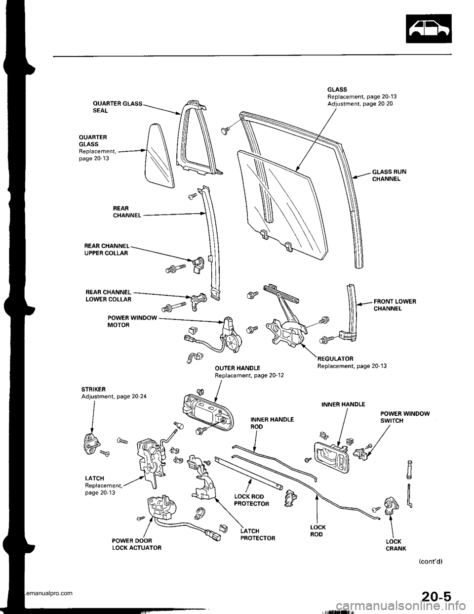
OUARTERSEAL
OUARTERGLASSReplacement,page 20-13
-flHiili^'i--_Fffi
POWER WINDOWMOTOR
REAR CHANNEL-\UPPERCOLLAR -.-----_----_-""
trw
page 20 2L
LATCHReplacement,page 20'13
POWEB DOORLOCK ACTUATOB
,6S
REGULATORReplacement, page 20'13
GLASS RUNCHANNEL
FRONT LOWERCHANNEL
STRIKERAdjustment,
l
I
W*
INN€R HANDLE
/ eowea wrruoow
I sYtfcH
s /* /
M-q/-\
LOCK RODPROTECTORCItr'6,1-
iI
\LOCKCRANK
LATCHPROTECTOB
(cont'd)
20-5
www.emanualpro.com
Page 1001 of 1395
Doors
Tailgate Door Weatherstrip
Replacement
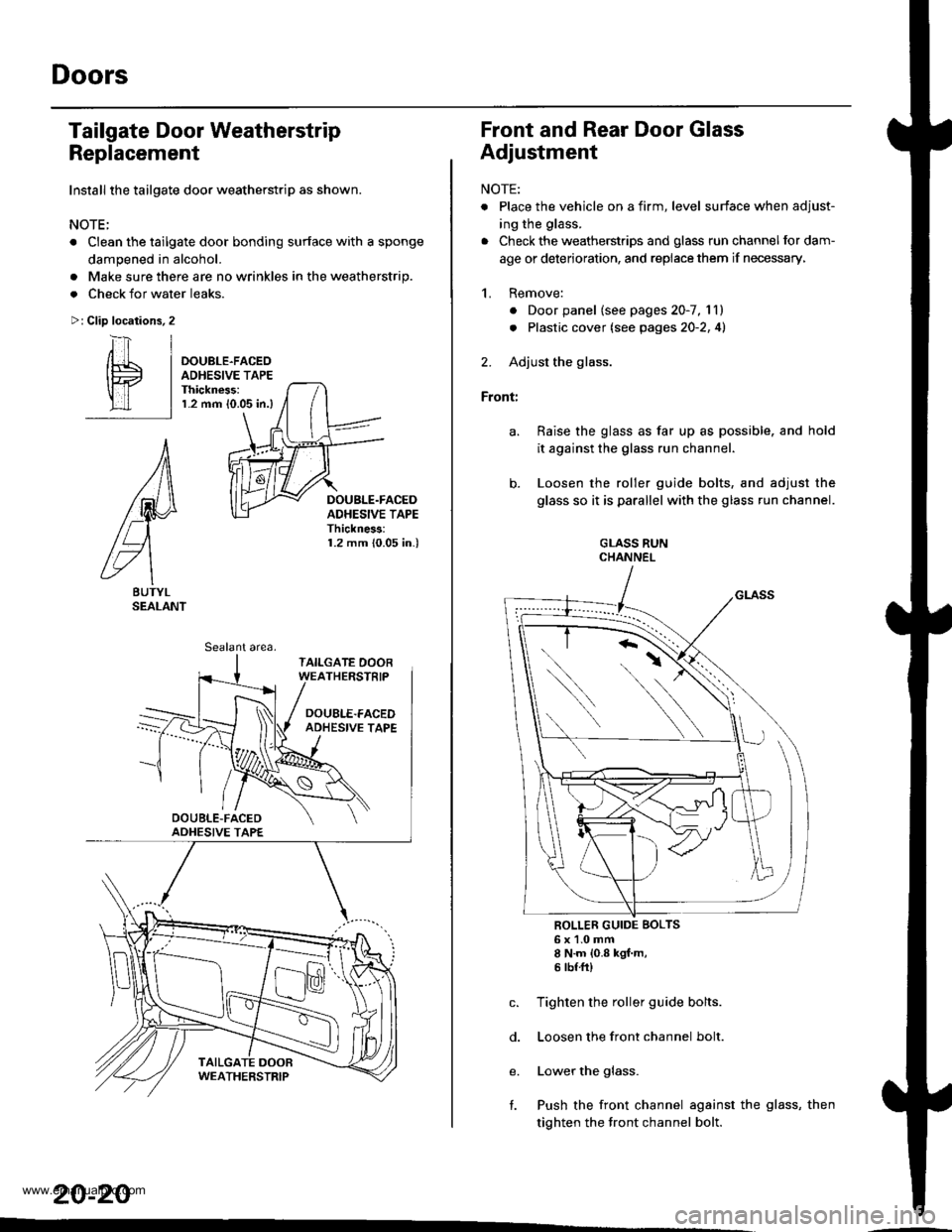
Install the tailgate door weatherstrip as shown.
NOTE;
. Clean the tailgate door bonding surface with a sponge
dampened in alcohol.
Make sure there are no wrinkles in the weatherstrip.
Check for water leaks.
Clip locations, 2
a
a
>:
i-t] |
/[L I oouere-rrceo
lE I aDHEsrvE rAPE
ll 1T I Thickness:
lll I r.2 mm lo.o5 in.)
A
lM
/L)
g\
BUTYLSEALANT
DOUBLE.FACEDADHESIVE TAPEThickne$:1.2 mm 10.05 in.)
Sealant area,
20-20
Front and Rear Door Glass
Adjustment
NOTE:
. Place the vehicle on a firm, level surface when adjust-
ing the glass.
. Check the weatherstrips and glass run channel for dam-
age or deterioration, and replace them if necessary,
1. Remove:
. Door panel (see pages20-7, lll
. Plastic cover (see pages2O-2,41
2. Adjust the glass.
Front:
Raise the glass as far up as possible. and hold
it against the glass run channel.
Loosen the roller guide bolts, and adjust the
glass so it is parallel with the glass run channel.
GLASS RUNCHANNEL
ROLLER GUIDE BOLTS6x1.0mm8 N.m {0.8 kgf.m,5 tbffi)
Tighten the roller guide bolts.
Loosen the front channel bolt.
Lower the glass.
Push the front channel against the glass, then
tighten the tront channel bolt.
e.
l.
www.emanualpro.com
Page 1003 of 1395
Doors
Front and Rear Door Glass
Adiustment (cont'dl
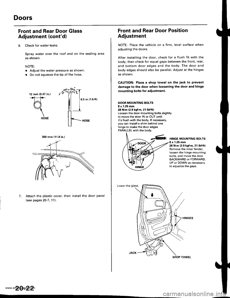
6. Check for water leaks.
Spray water over the roof and on the sealing area
as snown.
NOTE:
. Adjust the water pressure as shown.
. Do not soueeze the tio of the hose.
12 mm {0.47 in.l
#
(r\"1
HOSE
-"'*r"i
,'r)"f
tl
0.5 m (1.6 ftl
7. Attach the plastic cover, then install the door panel
(see pages 20-7, 'l 1),
20-22
..-
300 mm 111.8 in.)
Front and Rear Door Position
Adjustment
NOTE: Place the vehicle on a firm, level surface when
adiusting the doors.
After instailing the door, check for a flush fit with the
body, then check lor equal gaps between the front, rear.
and bottom door edges and the body. The door and
body edges should also be parallel. Adjust at the hinges
as shown.
CAUTION: Placa a shop towel on the iack to prevent
damage to the door when loosening the door and hinge
mounting bolts lor adiustment.
DOOR MOUNTING BOLTSI x 1.25 mm28 N.m 12.9 kgtr.m, 21 lbI.ftlLoosen the door mounting bolrs slighrlyto movethe door lN or OUT untilit's flush with the bodv. lf necessary,you can installa shim behind onehinge to make the door edgesPARALLEL with the bodv.
HINGE MOUNTING BOLTS8 x 1.25 mm28 N,m 12.9 kgt.m. 21 lbl.ftlRemove the inner fender,loosen the hinge mountingbolts, and move the doorBACKWARD or FORWARD,UP or DOWN as necessaryto equalize the gaps.
Lower the glass.
www.emanualpro.com
Page 1005 of 1395
Doors
(cont'd)
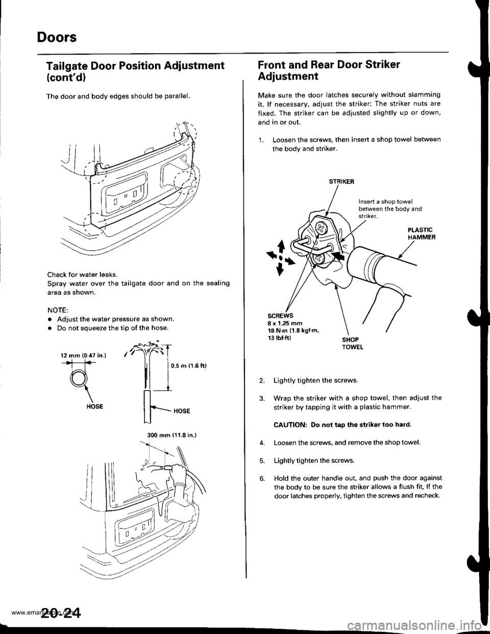
The door and body edges should be parallel.
Check for water leaks.
Spray water over the tailgate door and on the sealing
area as shown.
NOTE:
. Adjust the water pressure as shown.
. Do not squeeze the tip ofthe hose.
Tailgate Door Position Adiustment
-€*4
,'r)"C
II
0.5 m {1.6 ft}
20-24
l2 mm (0.47 in.).*1:]*
d3"1
HOSE
300 mm {11.8 in.l
Front and Rear Door Striker
Adjustment
Make sure the door latches securely without slamming
it, lf necessary, adjust the striker: The striker nuts are
fixed. The striker can be adjusted slightly up or down,
and in or out.
1. Loosen the screws, then insert a shop towel between
the body and striker.
Insert a shop towelbetween the body and
scREws8 x 1 .25 mm18 N.m (1.8 kgt.m,13 rbf.ft)
2.
J.
Lightly tighten the screws.
Wrap the striker with a shop towel, then adjust the
striker by tapping it with a plastic hammer.
CAUTION: Do not tap the striksr loo hard.
Loosen the screws. and remove the shop towel.
Lightly tighten the screws.
Hold the outer handle out, and push the door against
the body to be sure the striker allows a flush fit, lf the
door latches properly. tighten the screws and recheck.
4.
5.
6.
STRIKER
www.emanualpro.com
Page 1016 of 1395
22.
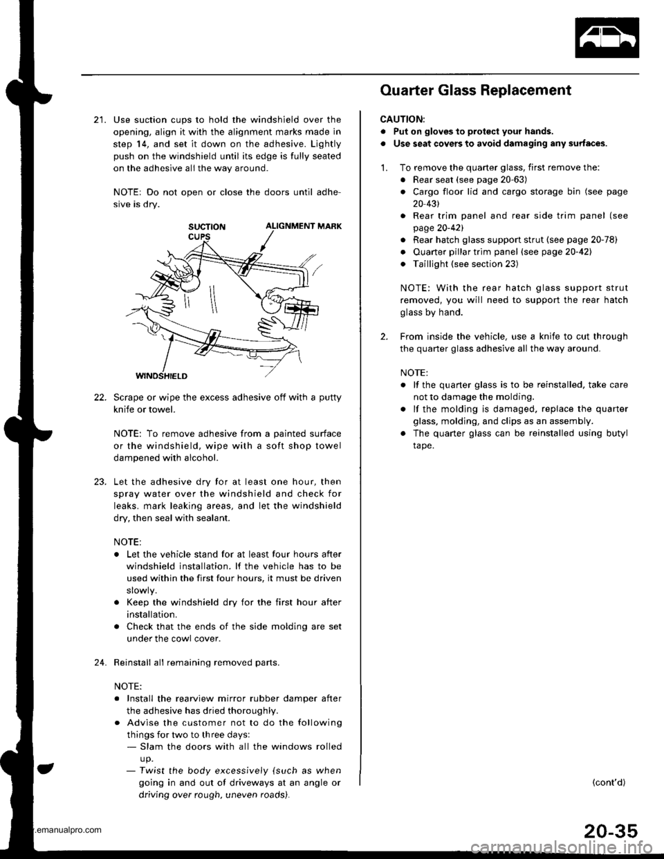
21. Use suction cups to hold the windshield over the
opening, align it with the alignment marks made in
step 14, and set it down on the adhesive. Ljghtly
push on the windshield until its edge is fully seated
on the adhesive all the way around.
NOTEr Do not open or close the doors until adhe-
sive is dry.
SUCTTON ALIGNMENT MARK
Scrape or wipe the excess adhesive off with a putty
knife or towel.
NOTE: To remove adhesive from a painted surface
or the windshield, wipe with a soft shop towel
dampened with alcohol.
Let the adhesive dry for at least one hour, then
spray water over the windshield and check for
leaks. mark leaking areas, and let the windshield
dry, then seal with sealant.
NOTE:
. Let the vehicle stand for at least four hours after
windshield installation. lf the vehicle has to be
used within the first four hours, it must be driven
. Keep the windshield dry for the first hour after
installation.
. Check that the ends of the side molding are set
under the cowl cover.
Reinstall all remaining removed parts.
NOTE:
. Install the rearview mirror rubber damper after
the adhesive has dried thoroughl,.
. Advise the customer not to do the following
things for two to three days:- Slam the doors with all the windows rolled
up.- Twist the body excess,vely {such as when
going in and out of driveways at an angle or
driving over rough. uneven roads).
24.
Ouarter Glass Replacement
CAUTION:
. Put on gloves to prot€ct your hands.
. Use seat covers to avoid damaging any surfaces.
1. To remove the quarter glass, first remove the:
. Rear seat (see page 20-63)
. Cargo floor lid and cargo storage bin (see page
20 431
. Rear trim panel and rear side trim panel (see
page 20-421
. Rear hatch glass support strut (see page 20-78)
. Ouarter pillar trim panel (see page20-421
. Taillight (see section 23)
NOTE: With the rear hatch glass support strut
removed, you will need to support the rear hatch
glass by hand.
2. From inside the vehicle, use a knife to cut through
the quarter glass adhesive all the way around.
NOTE:
. lf the quaner glass is to be reinstalled, take care
not to damage the molding.
. lf the molding is damaged. replace the quarter
glass, molding, and clips as an assembly.
. The quarter glass can be reinstalled using butyl
tape.
(cont'd)
20-35
www.emanualpro.com
Page 1020 of 1395
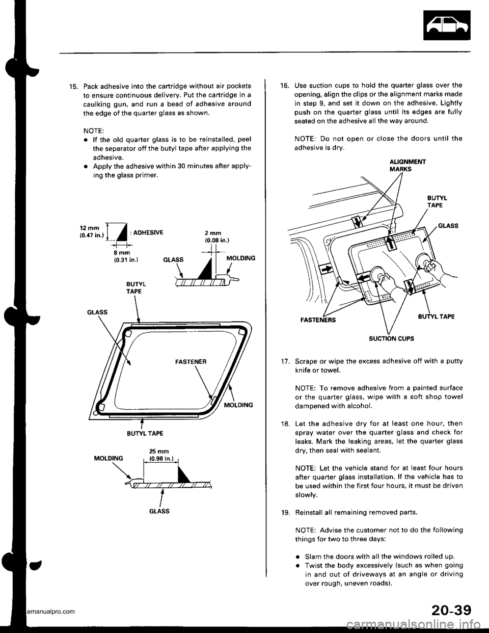
15. Pack adhesive into the cartridge without air pockets
to ensure continuous delivery, Put the canridge in a
caulking gun, and run a bead of adhesive around
the edge of the quarter glass as shown.
NOTE:
. lf the old quarter glass is to be reinstalled, peel
the separator off the butyl tape after applying the
adhesive.
. Apply the adhesive within 30 minutes after apply-
ing the glass primer.
i:.8T".,1,/:AoHEsrvE
I rnm(0.31 in.)
BUTYLTAPE
GLASS19.
20-39
16. Use suction cups to hold the quarter glass over the
opening, align the clips or the alignment marks made
in step 9, and set it down on the adhesive. Lightly
push on the quaner glass until its edges are fully
seated on the adhesive all the way around.
NOTE: Do not open or close the doors until the
adhesive is drv.
Scrape or wipe the excess adhesive off with a putty
knife or towel,
NOTE: To remove adhesive from a painted surface
or the quarter glass, wipe with a soft shop towel
dampened with alcohol.
Let the adhesive dry for at least one hour. then
spray water over the quarter glass and check for
leaks. Mark the leaking areas, let the quarter glass
dry, then seal with sealant.
NOTE: Let the vehicle stand for at least four hours
after quarter glass installation. lf the vehicle has to
be used within the first four hours, it must be driven
slowly.
Reinstall all remaining removed parts.
NOTE: Advise the customer not to do the following
things for two to three days:
. Slam the doors with all the windows rolled up.
. Twist the body excessively (such as when going
in and out of driveways at an angle or driving
over rough, uneven roads).
11.
18.
AUGNMENT
SUCTION CUPS
www.emanualpro.com
Page 1395 of 1395
Airbag/Seat Belt Tensioner
1.
Disposal (cont'dl
Connect a 12 volt battery to the tool'
. It the green light on the tool comes on, the air-
bag igniter circuit is defective and cannot deploy
the airbag. Go to Damaged Airbag Special
Procedure.
.lftheredlightonthetool comes on, the airbag is
ready to be deployed.
Push the tool's deployment switch. The airbag
should deploy (deployment is both highly audible
and visible; a loud noise and rapid inflation of the
bag, followed by slow deflation).
. lf the airbags deploy and the green light on the
tool comes on, continue with this procedure.
. lf an airbag doesn't deploy, yet the green light
comes ON, its igniter is defective. Go to Dam-
aged Airbag Special Procedure.
. During deployment, the airbag can become hot
enough to burn you, Wait thirty minutes after
deployment before touching the airbag.
Dispose of the complete airbag. No part of it can be
reused. Place it in a sturdy plastic bag, and seal it
securety.
CAUTION:
. Wear a faco shield and gloves when handling a
deployed airbag.
. Wash your hands and rinse them well with
water after handling a deployed airbag.
24-98
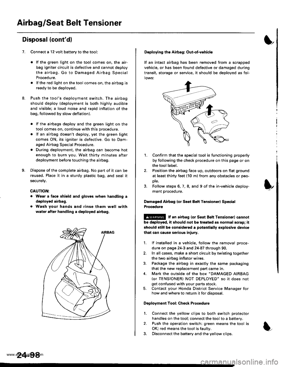
Deploying tho Airbag: Out-ot.vohicle
lf an intact airbag has been removed from a scrapped
vehicle, or has been found defective or damagsd during
transit. storage or seryice, it should be deployed as fol-
lows:
'L Confirm that the special tool is functioning properly
by following the check procedure on this page or on
the tool label.
2. Position the airbag face up, outdoors on flat ground
at least thirty feet (10 m) from any obstacles or peo-
Dte,
3. Follow steps 6, 7, 8. and 9 of the in-vehicle deploy-
ment proceoure.
Dlmaged Airbsg {or Seat Beh Ten3ion6r} Sp6cial
Procgdure
!@ r an airbag {or seat Beh rensioner} cannol
be doployod, it should not be treated as normal scrap; it
should still be considered a pot€ntially explosive device
lhat can cause serious iniury.
1. lf installed in a vehicle. follow the removal proce-
dure on page 24-3 and 24-87 through 90.
2. In all cases, make a short circuit by twisting together
the two airbag inflator wires.
3. Package the airbag in exactly the same packaging
that the new reDlacement Dart came in.
4. Mark the outside of the box "DAMAGED AIRBAG
{or TENSIONER) NOT DEPLOYED" so it does not
get confused with your parts stock.5. Contact your Honda District Service Manager forhow and where to return it for disposal.
Deployment Tool: Check Procedure
Connect the yellow clips to both switch protector
handles on the tool; connect the tool to a battery.
Push the operation switch: green means the tool is
OK: red means the tool is faultv.
Disconnect the baftery and the yellow clips.
I
t
l.
www.emanualpro.com