2000 HONDA CR-V Power steering return
[x] Cancel search: Power steering returnPage 849 of 1395

Troubleshooting
General Troubleshootin g
Check the following before you begin:
. Has the suspension been modified in a way that would affect steering?
. Are tire sizes, tire variety and air pressure correct?
. ls the steering wheel original equipment or equivalent?
. ls the power steering pump belt properly adjusted?
. ls steering fluid reservoir filled to proper level?
. ls the engine idle speed correct and steady?
Hard Steering (Check the power assist, see page 17-12. lf the force is over 29 N (3.0 kgl 6.6 lbfl, proceed with this troubleshooting.i
Abnormalthiidpressure (Iluidpressure is toohigh)
Relief pressuretoo low
Faulty valve body unit
Abnormal
Check the teed and return circuit lines and hosebetween the gearbox and pump for clogging anddeformation.
Normal line and hose
Check the pump fluid pressure(see page 17-16 or 17-17).Measure steady state lluid pres-
sure at idle with the pressure con-trol valve and the shut-off valve (it
so equipped) fully open.The fluid pressure should be 1,500kPa (15 kgf/cm,,213 psi)or less.
Normal
Check the flow control valve (see page 17 26).. Check the valv€ lor smooth movement in the hous-ing.. Check the relief valve for leaks.
Check the pump fluid pressure(see page 17-16 or l7-17).Measure pump relief pressure atidle with the pressure controlvalve and the shut'off valve lil soequipped) fully closed.The fluid pressure should be 6,9007,800 kPa (70 - 80 kgflcm,, 1,000- 1,140 psi).
Normal relief pressure
17-4
Go to page 17 5Faulty pump assemblyFaulty flow control valve
www.emanualpro.com
Page 851 of 1395
Troubleshooting
General Troubleshooting (cont'dl
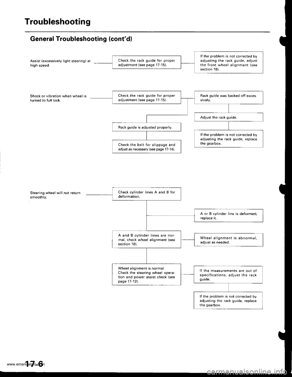
Assist (excessively light steering) athigh speed.
Shock or vibration when wheel isturned to full lock.
Steering wheel will not returnsmoothly.
lf the problem is not corrected byadjusting the rack guide, adjustthe front wheel alignment (see
section 18).
Check the rack guide for proper
adjustment (see page 17-15).
Check the rack guide for properadjustment (see page 17'15).
Adjust the rack guide.
Rack guide is adiusted properly.
lf the problem is not corrected byadjusting the rack guide, replacethe gearbox.Check the belt for slippage andadjust as necessary (see page 17-14).
A and B cylinder lines are normal, check wheel alignment (see
section 18).
Wheel alignment is abnormal,adjust as needed.
Wheel alignment is normal.Check the steering wheel opera-tion and power assist check (seepage 17-121.
lf the measurements are out ofspecifacations, adjust the rackguade.
lf the problem is not corrected byadjusting the rack guide, replacethe gearbox,
www.emanualpro.com
Page 860 of 1395
Rack Guide Adjustment
1.
6.
7.
5.
4.
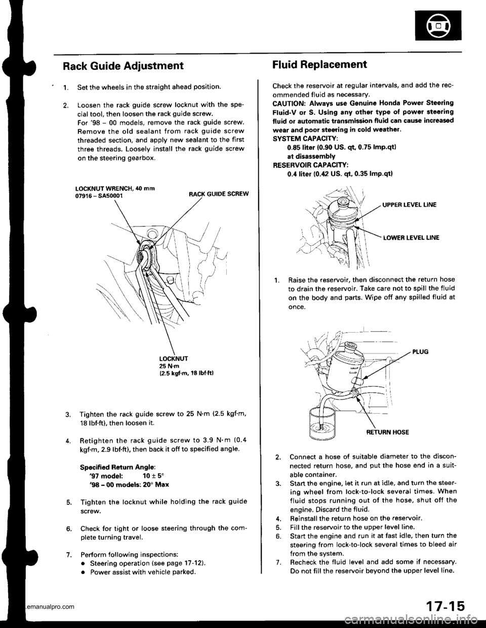
Set the wheels in the straight ahead position.
Loosen the rack guide screw locknut with the spe-
cialtool, then loosen the rack guide screw.
For'98 - 00 models, remove the rack guide screw.
Remove the old sealant from rack guide screw
threaded section, and apply new sealant to the first
three threads. Loosely install the rack guide screw
on the steering gearbox.
RACK GUIDE SCREW
LOCKNUT25 N.m
12.5 kgt m, 18lbtftl
Tighten the rack guide screw to 25 N.m (2.5 kgf'm,
18 lbf.ft), then loosen it.
Retighten the rack guide screw to 3.9 N'm (0.4
kgf.m, 2.9 lbf.ft), then back it off to specified angle.
Specified Return Anglo:
37 model: 10 r 5"'98 - 00 modeb: 20' Max
Tighten the locknut while holding the rack guide
screw.
Check for tight or loose steering through the com-
plete turning travel.
Perform following inspections:
. Steering operation (see page 17-12).
. Power assist with vehicle parked
Fluid Replacement
Check the reseryoir at regular intervals, and add the rec-
ommended fluid as necessary.
CAUTION: Always use Gsnuine Honda Power Steering
Fluid-V or S. Using any other type of power steering
tluid or automatic transmission fluid can cause increassd
wear and poor steering in cold w3athel.
SYSTEM CAPACITY:
0.85 liter {0.90 US. qt. 0.75 lmp.qtl
at disasssmbly
RESERVOIR CAPACITY:
0.,1 liter (0.42 US. gt, 0.35 lmp.qi)
UPPEN LEVEL LINE
LOWER LEVEL LINE
1.Raise the reservoir. then disconnect the return hose
to drain the reservoir. Take care not to spill the fluid
on the body and parts. Wipe off any spilled fluid at
once.
2, Connect a hose of suitable diameter to the discon-
nected return hose, and put the hose end in a suit-
able container.
3. Stan the engine. let it run at idle, and turn the steer-
ing wheel from lock-to-lock several times. When
fluid stops running out of the hose, shut off the
engine. Discard the fluid.
4. Beinstallthe return hose on the reservoar.
5. Fill the reservoir to the upper level line,
6. Start the engine and run it at fast idle. then turn the
steering from lock-to-lock several times to bleed air
from the system.
7. Recheck the fluid level and add some if necessary.
Do not fill the reservoir beyond the upper level line.
www.emanualpro.com
Page 868 of 1395

Power Steering Hoses, Lines
Fluid Leakage Inspection
HOSES and LINES
. lnspect hoses for damage. leaks. interference and twisting
. Inspect fluid linesfor damage, rusting and leakage.
. Check for leaks at hose and line joints and connections.
FEED HOSE37 N.m 13.8 kgf.m, 27 lbtft)RETURN LINE JOINT28 N.m (2.9 kgf.m.21 lbf.ftl
CYLINDER LINES17 N.m (1.7 kgf.m. 12 lbf.ftl
FOWER STEERING PRESSURE SWITCH12 N.m (1.2 kgf.m,8.7 lbtft)
26 N.m (2.7 kgf.m, 20 lbf.ft)
GEARBOX .nd VALVE BODY UNllCheck for leaks at the mating surfaceand flare nut connections.
CYLINDER
FEED HOSE11 N.m('1.1 kgt.m, 8 lbf.ftl
SUCTION HOSE
PUMP ASSEMBLYCheck for leaks atthe pump
seal. inlet and outlet fittings.
Note these items during installation:
. Connect each hose to the corresponding line securely
until it contacts the stop on the line. Install the clamp
or adjustable clamp at the specified distance from the
hose end as shown.
. Check all clamDs for deterioration or deformation;
replace with the clamps new ones if necessary.
. Add the recommended power steering fluid to the
specified level on the reservoir and check for leaks.
ADJUSTABLE HOSE CLAMP: la)
. Position the adjustable hose clamps at the points
indicated by (a) in the drawing above.
. Slide the hose over the line until it contacts the stop.
HOSE CLAMP: lbl
. Position the hose clamps at the
(b) in the drawing above.
. Slide the hose over the line until
Replacement
10.01 - 0.22 in)
points indicatsd by
it contacts the stop,
2.0 - 4.0 mm10.08 - 0.16 inl2.5 - 5.5 mm{0.01 - 0.22 in}17 -23
www.emanualpro.com
Page 877 of 1395
Power Steering Gearbox
AN'USTABLE HOSE CLAMP
Removal (cont'dl
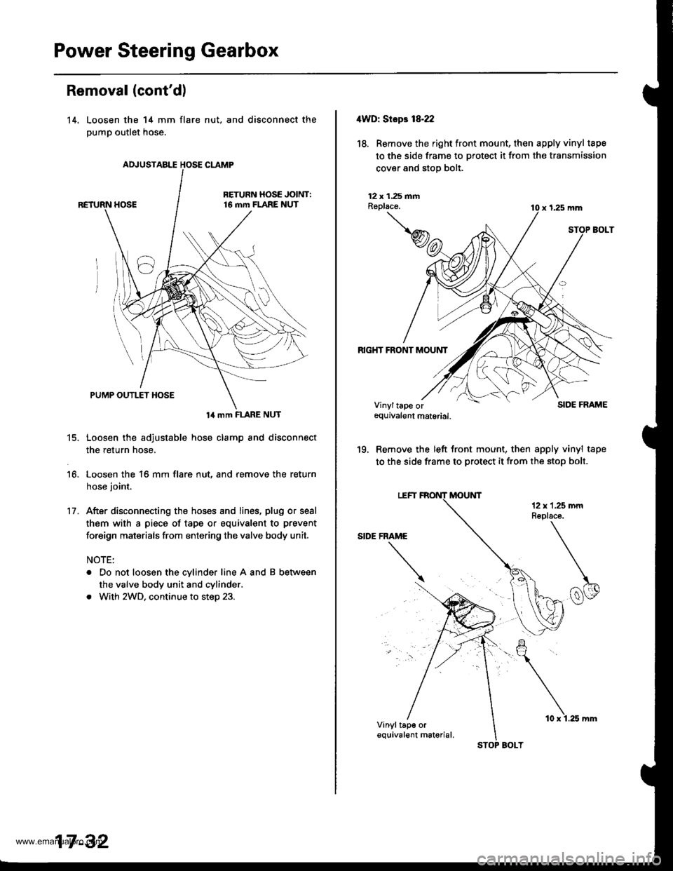
14. Loosen the 14 mm flare
pump outlet hose.
nut, and disconnect the
14 mm FLARE NUT
15. Loosen the adjustable hose clamp and disconnect
the return hose,
16. Loosen the 16 mm flare nut, and remove the return
hose joint.
17. After disconnecting the hoses and lines, plug or seal
them with a piece of tape or equivalent to prevent
foreign maisrials from entering the valve body unit.
NOTE:
. Do not loosen the cylinder line A and B between
the valve body unit and cylinder.
. With 2WD, continue to step 23.
17 -32
STOP BOLT
10 x 1.25 mm
4WD: Stepr 18-22
18. Removethe right tront mount, then apply vinyl tape
to the side frame to protect it from the transmission
cover and stop bolt.
12 x 1.25 fiiAReplace.
RIGHT FRONT MOUNT
x 1,25 mm
SIDE FRAME
'19. Remove the left front mount, then apply vinyl tape
to the side frame to protect it from the stop bolt.
Vinyltape orequivalgnt material.
Vinyltap€ orequival€nt m6terial.
www.emanualpro.com
Page 896 of 1395
lnstallation
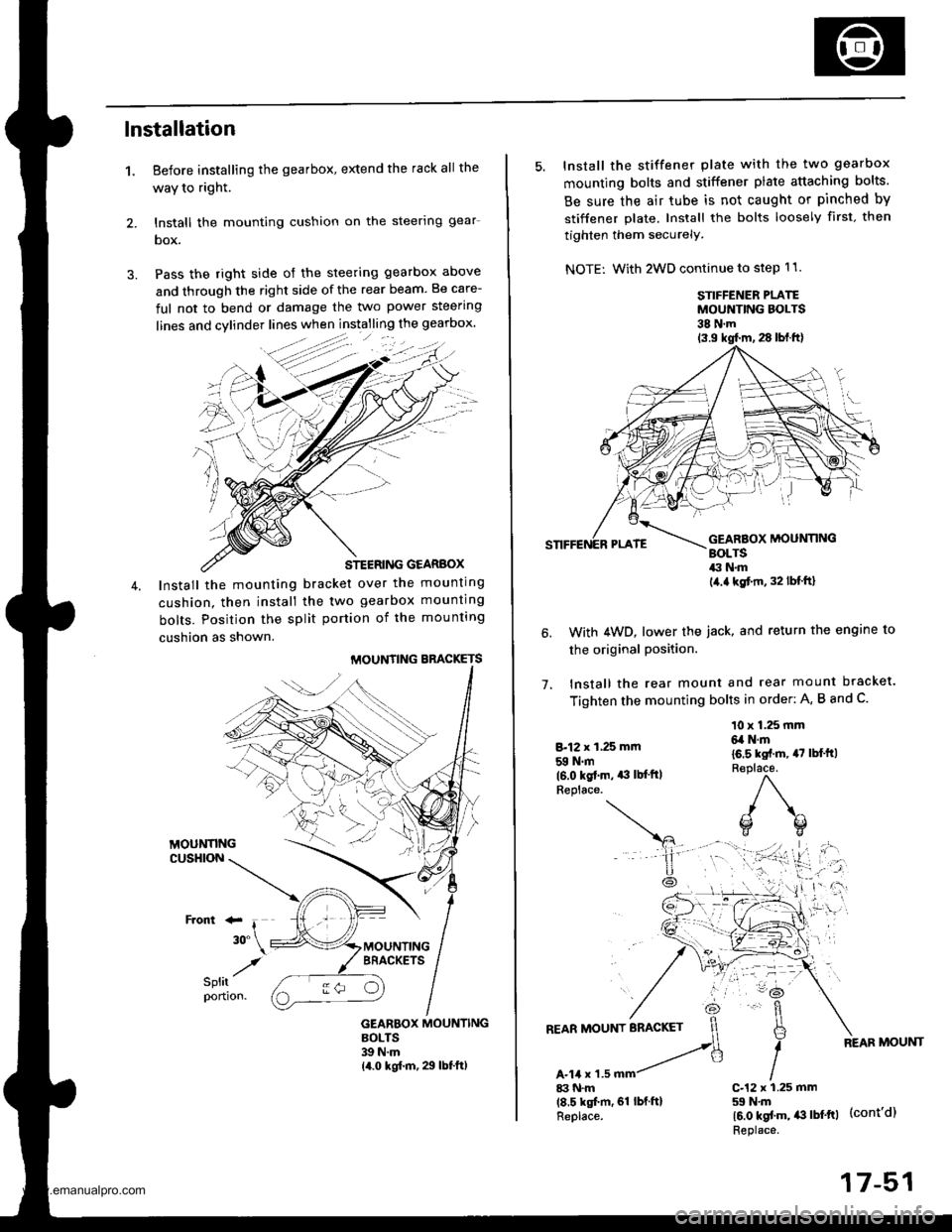
1. Before installing the gearbox, extend the rack all the
waY to right.
2. lnstall the mounting cushion on the steerlng gear-
box.
3. Pass the right side of the steering gearbox above
and through the right side of the rear beam. Be care-
ful not to bend or damage the two power steering
STEERING GEARBOX
Install the mounting bracket over the mounting
cushion. then install the two gearbox mounting
bolts. Position the split portion of the mounting
cushion as shown.
MOUNTING BBACKETS
GEARBOX MOUNTINGBOLTS39 N.m14.0 kgf.m, 29 lbf.ft)
:-
/
5. Install the stiffener plate with the two gearbox
mounting bolts and stiffener plate attaching bolts.
Be sure the air tube is not caught or pinched by
stiffener plate. Install the bolts loosely first. then
tighten them securely.
NOTE: With 2WD continue to step 11.
STIFFENER PLATEMOUNTING BOLTS38 N.m
1.
With 4WD, lower the iack, and return the engine to
the original Position.
lnstall the rear mount and rear mount bracket.
Tighten the mounting bolts in order: A, B and C.
8.12 x 1,25 mm
59 N.m(6.0 kgt.m. *l lb{'ftlReplace.
10 x 1.25 mm6,a N.m
16.5 kst.m, 47 lbl'ft)R€place.
)\^
o(]
17-51
www.emanualpro.com
Page 897 of 1395
Power Steering Gearbox
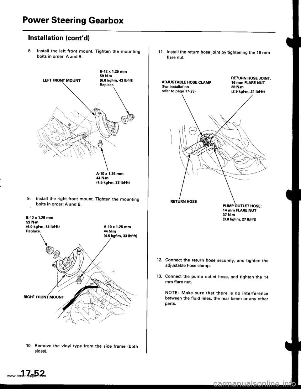
Installation (cont'd)
8, Install the left front mount. Tighten the mountingbolts in order: A and B.
LEFT FRONT MOUNT
B-12 x 1,25 mm59Nm(6.0 kgtm,,€ lbl.ftlReplaca.
9. Instsll the right front mount, Tighten the mountingbolts in order: A and B.
B-12 x 1.25 mm59 N.m16.0 ks[.m, ,|:| lbf.ftlReplace.
A-10 x 1.25 mm4,1 N.mla.s kgt m, 33 lbf.ft)
A-10 x 1.25 mma,a N.m
10. Remove the vinyl type from the side frame (both
sides).
17-52
11. Installthe return hose joint by tightening the 16 mmflare nut.
AD.'USTAB[T HOSE CLAMP(For installationreter to page 17,23)
RETURN HOSE JOINT:16 mm FLARE NUT28 N.m12.9 kg{.m.21 lbt{t)
14 mm FLARE NUT37 N.m(3.8 ksf.m, 27 lbl'frl
't2.
13.
Connect the return hose securely. and tighten theadjustable hose clamp.
Connect the pump outlet hose, and tighten the l4mm flare nut.
NOTE: Make sure that there is no interferencebetween the fluid lines, the rear beam or any otherparts.
www.emanualpro.com
Page 1153 of 1395
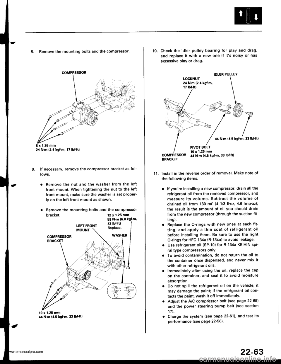
8. Remove the mounting bolts and the compressor.
E x 1.25 mm2a N.m (2.,1kgf.m, l7 lbl.ft)
lf necessary, remove the compressor bracket as fol-
lows.
. Remove the nut and the washer from the left
front mount. When tightening the nut to the left
front mount, make sure the washer is set proper-
ly on the left front mount as shown.
. Remove the mounting bolts and the compressor
bracket.
q
12 x 1.25 mm
59 N.m (6.0 kgt'm,
10 x 1,25 mmart N.m (4.5 kgf'm, 33 lbfftl
11.
10. Check the idler pulley bearing for play and drag,
and replace it with a new one if it's noisy or has
excessive play or drag.
lnstall in the reverse order of removal. Make note of
the following items,
. lf you're installing a new compressor, drain all the
reJrigerant oil from the removed compressor, and
measure its volume. Subtract the volume of
drained oil trom 130 m/ 14 U3 fl'o2,4.6 lmp'oz);
the result is the amount of oil you should drain
lrom the new compressor (through the suction fit-
trngl.
. Replace the O-rings with new ones at each fit-
ting, and apply a thin coat o{ refrigerant oil
before installing them. Be sure to use the right
O-rings for HFC-134a (R-134a) to avoid leakage.
. Use refrigerant oil (SP-10) for R-134a KEIHIN spi-
ral type compressors only.
. To avoid contamination, do not return the oil to
the container once dispensed, and never mix it
with other refrigerant oils.
. lmmediately after using the oil, replace the cap
on the container. and seal it to avoid moisture
aDsorprlon.
. Do not spill the refrigerant oil on the vehicle; it
may damage the paint; if the retrigerant oil con-
tacts the Daint, wash it off immediately.
. Adjust the Ay'C compr'essor b€lt (see psge 22-69)
and the power steering pump belt {see section
17t.
. Charge the system (see page 22-611, and test its
performance (see page 22-56]-.
IDLER PULLEY
+r N.m 14.5 kgt m,33lbf ftl
PIVOT BOLT10 x 1.25 mmir4 N.m {4.5 kgt m, 33 lbl'ft}BBACKET
www.emanualpro.com