2000 HONDA CR-V clock
[x] Cancel search: clockPage 35 of 1395
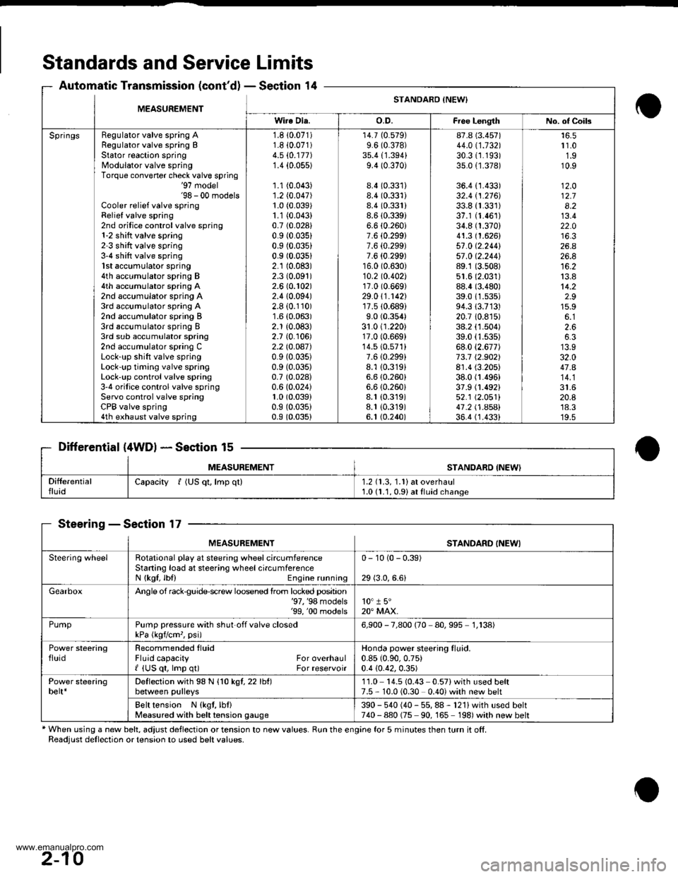
Standards and Service Limits
Automatic Transmission (cont'dl - Section 14
Differential (4WDl * Section 15
MEASUREMENTSTANOABD {NEW'
SteeringSection 17
* When using a new belt, adjust deflection or tension to new values. Run the engine for 5 minutes then turn it off.Readjust dellection or tension to used belt values.
MEASUREMENTSTANDARO INEWI
Wire Dia.o.D.Fiee LengthNo. of Coils
SpringsRegulator valve spring ARegulator valve spring BStator reaction springModulator valve springTorque convener check valve spring'97 model'98 - 00 modelsCooler relief valve springRelief valve spring2nd orilice control valve spring1-2 shitt valve spring2 3 shift valve spring3-4 shift valve spring1st accumulator spring4th accumulator spring B4th accumulator spring A2nd accumulator spring A3rd accumulator spring A2nd accumulator spring B3rd accumulator spring I3rd sub accumulator spring2nd accumulator spring CLock-up shift valve springLock-up timing valve springLock'up control valve spring3'4 orifice control valve springServo control valve springCPB valve spring4th exhaust valve spring
1.8 10.071)1.8 i0.071)4.5 (0.177)
1.4 {0.055)
1.1 (0.043)
1.2 (0.047)
1.0 (0.039)
1.1 (0.043)
0.7 (0.028)
0.9 (0.035)
0.9 (0.035)
0.9 (0.03s1
2.1 (0.083)
2.3 (0.091)
2.6 (0.102)
2.410.094)2.8 (0.110)
1.6 (0.063)
2.1 (0.083)
2.7 {0. r06)2.2lO.OA7)0.9 (0.035)
0.9 (0.035)
0.7 (0.028)
0.6 (0.024)
1.0 (0.039)
0.9 (0.035)
0.9 (0.035)
14.7 (0.579)
9.6 (0.378)
35.4 {1.394}9.4 (0.370)
8.4 (0.331)
8.4 (0.331)
8.4 (0.331)
8.6 (0.3391
6.6 (0.260i
7.6 {0.299}7.6 {0.299)7.6 {0.299)16.0 (0.630)
10.2 to.402l17.0 (0.669)
29.0 \1.1421'r7.510.689)
9.0 (0.354)
31.0 (1.220)17.0 (0.669)
14.510.571)7.610.299i8.1 {0.319}6.6 (0.260)
6.6 (0.260i
8.1 (0.319)
8.1 {0.319)6. t (0.240)
87.8 (3.457)
44.011.132130.31r.193)35.0 {1.378)
36.4 {1.433)32.4 tl.216J33.8 {r.331)37.1 (1.461)
34.8 (1.370)
41.3 (1.626)
57 .0 (2.2441
57 .0 12.244189.1 (3.508)
51.6 (2.031)
88.4 (3.480)
39.011.s35)94.313.713)20.7 10.8r5)38.2 (1.504)
39.0 (1.535)
68.0 (2.677)
73.7 12.902)8r.4 (3.205)
38.0 fl.496)37.9 (1.492)
52.1 (2.051)
41 .2 t .A5Al36.4 (1.4331
r 1.01.910.9
12.O12.78.213.422.0
26.426.8
13.814.22.915.9
2.66.3
32.047.A
20.8'18.3'19.5
Capacity f (US qt, lmp ql)1.2 (1.3, 1.1) at overhaul1.0 (1.1, 0.91 at fluid change
MEASUREMENTSTANDARD INEWI
Steering wheelRotational play at steering wheel circumferenceStaning load at steering wheelcircumferenceN {kgf, lbl) Engine running
0- 10 (0 - 0.39)
29 (3.0,6.6)
GearboxAngle of rack$uide-screw loosened lrom locked position'97, '98 models'99, '00 models10" 1 5"20" MAX.
PumpPump pressure with shut off valve closedkPa (kgvcm,, psi)6,900 - 7,800 (70 80,995 1,138)
Power steeringfluidRecommended tluidFluid capacity For overhaulI {US qt, lmp q0 For reservoir
Honda power steering fluid.0.85 (0.90,0.75)
0.4 {0.42,0.35)
Power steeringbelt*Deflection with 98 N {1O kgl,22lht)between pulleys11.0 14.5 (0.43 0.57)with used belt7.5 - 10.0 (0.30 0.40) with new belt
Belt tension N {kgt, lbf}Measured with belt tension gauge390 - 540 (40 - 55, 88 - 121) with used belt740-880 (75 90, 165 198)with new belt
2-10
www.emanualpro.com
Page 37 of 1395
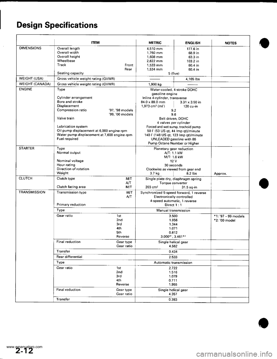
Design Specifications
ITEMMETRICENGLISHNOTES
DIMENSIONSOverall lengthOverallwidthOverall heightWheelbaseTrack FrontRearSeating capacity
4,510 mm1,750 mm1,608 mm2,622 mrn1,533 mm1,534 mm5lf
177.6 in68.9 in63.3 in103.2 in60.4 in60.4 in
WEIGHT (USA)Gross vehicle weight rating (GVWR)| 4,165 tbs
WEIGHT (CANADA)Gross vehicle weight rating (GVWR)1,900 kg
ENGINEType
Cylinder arrangementBore and strokeDisplacementCompression ratio '97,'98 mooers'99, '00 modelsValve train
Lubrication systemOil pump displacement at 6,000 engine rpmWater pump displacement at 7,600 engine rpmFuel required
Water-cooled, 4-stroke DOHCgasoline engineInline 4-cylinder, transverse84.0 x 89.0 mm.1,973 cm3 (m{)
9.2
3.31 x 3.50 in120 cu-in
9.6Belt driven, DOHC4 valves per cylinderForced and wet sump, trochoid pump501 (53 US qt,44 lmp qt)/minute1401 (148 US qt, 123 lmp qt)/minuteUNLEADED gasoljne with 86Pump Octane Number or Higher
STARTERTypeNormal output
NominalvohageHour ratingDirection of rotationWeight
Planetary gear reductionA/T: 1.1 kWM/T: 1.0 kW12V30 secondsClockwise as viewed from gear end3.7 kg 8.2 lbsApprox.
CLUTCHClutch type
Clutch lacing area
MIT
MIT
Single plate dry, diaphragm springTorque converter203 cm, 31.5 sq-in
TRANSMISSIONTransmission type
Primary redLrction
MITSynchronized s-speed torward, 1 reverseElectronically controlled4-speed automatic, 1 reverseDirect I : 1
TypeManualtransmission
Gear ratio 1st2nd3rd4th5thReverse
3.5001.9561.3441.0710.8123.000*,. 3.461*'
*1: '97 - 99 models*2: '00 model
Final reduction Gear typeGear rataoSingle helical gear4.562
Transfer0.434
Rear differential2.533
TypeAutomatic transmission
Gear ratio 1st2nd3rd4thReverse
2.722
1.0790.7111.955
Final reduction Gear typeGear ratioSingle helical gear4.357
Transfer0.393
2-12
www.emanualpro.com
Page 66 of 1395

lgnition System
5.
lgnition Timing Inspection and Setting
2.
1.Check the idle speed, and adjust it if necessary (see
section 1 1).
Pull out the service check connector 2P (BRN and
BLK wires) from the connector holder located under
the dash on the front passenger side, then connect
the scs service connector (P/N 07PAz - 0010100) to
it.
Start the engine. Hold the engine at 3,000 rpm with
no load (A/T in N or E, Mff in neutral) until the
radiator fan comes on, then let it idle.
Connect the timing light to the No. I ignition wire,
then point the light toward the pointer on the timing
belt cover.
Check the ignition timing in no load conditions:
headlights, blower fan, rear window defogger, and
air conditioner are not operating.
lgnition Timing:
M/T: 16" 12" BTDC (RED) idling in neutral
AlTt'16" !2" BTDC (RED) idling in E or E
CRANKSHAFTPULLEY
4-16
6. lf necessary, adjust the ignition timing as follows.
Loosen the distributor mounting bolts, and turn the
distributor ignition (Dl) housing counterclockwise to
advance the timing or clockwise to retard the tim-
t no,
7.
8.
MOUNTING BOLTS24 N.m {2.4 kgf m, 17 lbtft}
Tighten the distributor mounting bolts, and recheck
the ignition timing.
Disconnect the SCS service connector from the ser-
vice check connector.
To RETARD
www.emanualpro.com
Page 117 of 1395
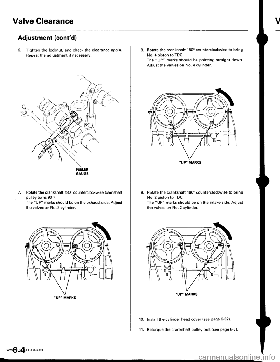
Valve Clearancev
Adjustment (cont'dl
6. Tighten the locknut, and check the clearance agajn.
Repeat the adjustment if necessary.
GAUGE
Rotate the crankshaft 180" counterclockwise (camshaft
pulley turns 90').
The "UP" marks should be on the exhaust side. Adjust
the valves on No. 3 cylinder.
.UP" MARKS
7.
8. Rotate the crankshaft 180" counterclockwise to brinq
No. 4 piston to TDC.
The "UP" marks should be pointing straight down.
Adjust the valves on No. 4 cylinder.
Rotate the crankshaft 180'counterclockwise to brino
No.2 piston to TDC.
The "UP" marks should be on the intake side. Adiust
the valves on No. 2 cylinder.
Install the cylinder head cover (see page 6-32).
Retorque the crankshaft pulley bolt (see page 6-7).
10.
11.
"UP" MARKS
"UP" MARKS
www.emanualpro.com
Page 122 of 1395

1.
2.
Inspection
Remove the cylinder head cover.
lnspect the timing belt for c.acks and oil or coolant
soaking. Replace the belt if it is oil or coolant
soaked. Remove any oil or solvent that gets on the
belt.
lnspect thisarea for wear.
After inspecting, retorque the crankshaft pulley bolt
to 177 N.m (18.0 kgnm, 130 lbf.ft).
Install the cylinder head cover (see page 6-32).
3.
Tension Adjustment
NOTE:
. Always adjust the timing belt tension with the engine
coto.
. Always rotate the crankshaft counterclockwise when
viewed from the pulley side. Rotating it clockwise
may result in improper adiustment of the belt ten-
sion.
'1. Remove the cylinder head cover
2. Set the No. 1 piston at TDC (see page.6-12).
3. Rotate the crankshaft five or six revolutions to set
the belt.
Set the No. 1 piston at TDC.
Loosen the adjusting bolt 1/2 turn (180') only.
4.
5.
ADJUSTING BOLT5,4 N.m (5.5 kgf.m,40 tbtftlFor adiustment only,
7.
8.
Rotate the crankshaft counterclockwise three teeth
on the camshaft pulley.
Tighten the adjusting bolt to the specified torque.
After adjusting, retorque the crankshaft pulley bolt to
177 N.m (18.0 kgf.m, 130 lbf.ft).
Installthe cylinder head cover (see page 6-32).9.
rotation,
6-9
www.emanualpro.com
Page 125 of 1395
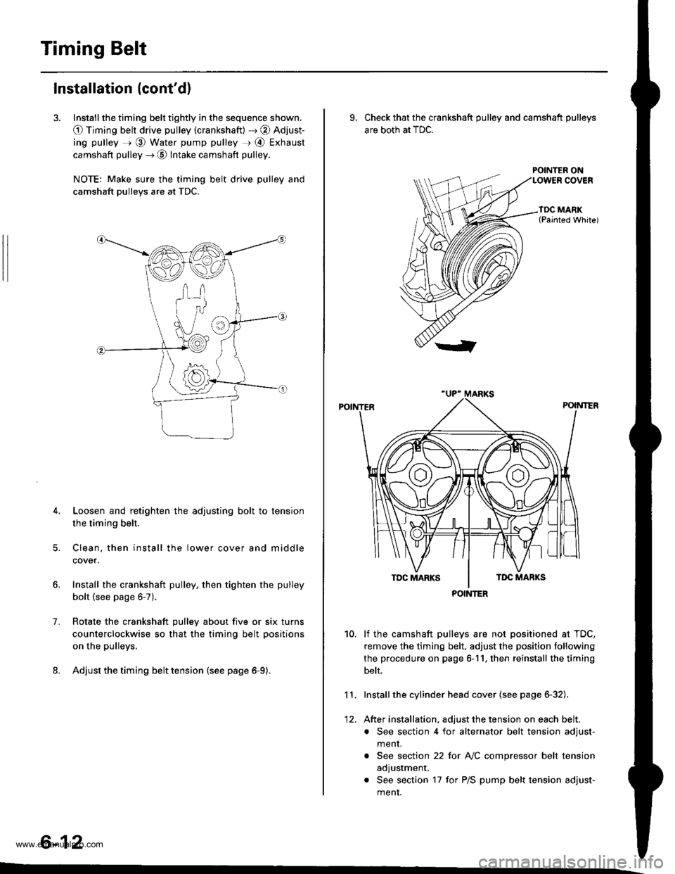
Timing Belt
Installation (cont'd)
3. Install the timing belt tightly in the sequence shown.
O Timing belt drive pulley (crankshaft) J @ Adjust-
ing pulley =r @ Water pump pulley r @ Exhaust
camshaft pulley --) @ Intake camshaft pulley.
NOTE: Make sure the timing belt drive pulley and
camshaft pulleys are at TDC.
4. Loosen and retighten the adjusting bolt to tension
the timing belt.
5. Clean. then install the lower cover and middle
cover.
Install the crankshaft pulley, then tighten the pulley
bolt (see page 6-7).
Rotate the crankshaft pulley about five or six turns
counterclockwise so that the timing belt positions
on the pulleys.
Adjust the timing belt tension {see page 6-9).
1.
6-12
9. Check that the crankshaft pulley and camshaft pulleys
are both at TDC.
POINTER ON
lf the camshaft pulleys are not positioned at TDC,
remove the timing belt. adjust the position following
the procedure on page 6-11. then reinstall the timing
belt.
Installthe cylinder head cover (see page 6-32).
After installation, adjust the tension on each belt.
. See section 4 for alternator belt tension adjust-
menr.
. See section 22 for NC compressor belt tension
adjustment.
. See section 17 for P/S pump belt tension adjust-
ment.
10.
11.
12.
POINTER
www.emanualpro.com
Page 140 of 1395
Cylinder Head
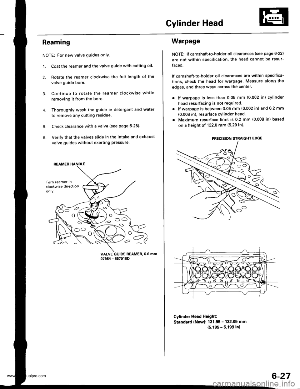
Reaming
NOTE: For new valve guides only.
1. Coat the reamer and the valve guide with cutting oil.
2. Rotate the reamer clockwise the full length of the
valve guide bore.
Continue to rotate the reamer clockwise while
removing it from the bore.
Thoroughly wash the guide in detergent and water
to remove anY cutting residue.
Check clearance with a valve (see page 6-25).
Verify that the valves slide in the intake and exhaust
valve guides without exerting pressure.
3.
4.
5.
6.
vALvE GUIDE REAMER,6.6 mm0798i1 - 657010O
REAMER HANDLE
e
Warpage
NOTE: lf camshaft-to-holder oil clearances (see page G22)
are not within specification, the head cannot be resur-
faced.
lf camshaft-to-holder oil clearances are within specifica-
tions, check the head for warpage. Measure along the
edges, and three ways across the center.
. if warpage is less than 0.05 mm (0.002 in) cylinder
head resurfacing is not required
lf warpage is between 0.05 mm (0.002 in) and 0.2 mm
(0.008 in), resurface cylinder head.
Maximum resurface limit is 0.2 mm (0.008 in) based
on a height of 132.0 mm (5.20 in).
Cylind€r Hesd Height:
Standard {New}: 131.95 - 132.05 mm
15.195 - 5.199 inl
PRECISION STRAIGHT EDGE
6-27
www.emanualpro.com
Page 166 of 1395
PistonsCrankshaft
Installation
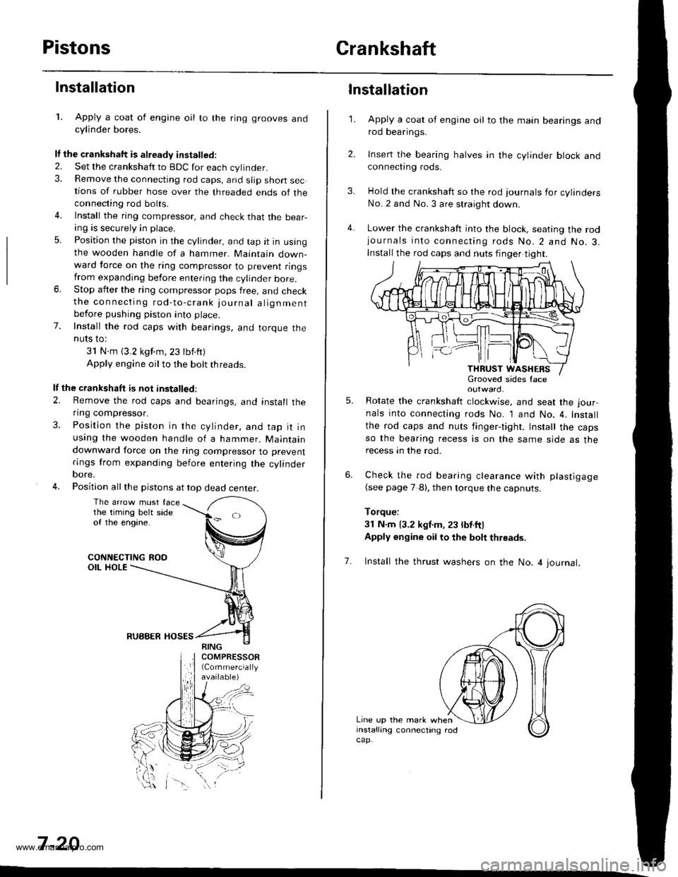
1. Apply a coat of engine oil to the ring grooves andcylinder bores.
It the crankshaft is already installed.
2. Set the crankshatt to BDC for each cylinder.3. Remove the connecting rod caps, and slip short sections of rubber hose over the threaded ends of theconnecting rod bolts.
4. lnstall the ring compressor, and check that the bear-ang is securely in place.
5. Position the piston in the cylinder, and tap it in usingthe wooden handle of a hammer. Maintain down-ward force on the ring compressor to prevent ringstrom expanding before entering the cylinder bore.6. Stop after the ring compressor pops free, and checkthe connecting rod-to-crank journal alignmentbefore pushing piston into place.
7. Install the rod caps with bearings, and torque theNUIS IO:
31 N.m (3.2 kgf.m,23 tbf.ft)
Apply engine oil to the bolt threads.
lf the crankshaft is not installed:
2. Remove the rod caps and bearings, and install theflng compressor.
3. Position the piston in the cylinder, and tap it inusing the wooden handle of a hammer. Maintaindownward force on the ring compressor to prevent
rings from expanding before entering the cylinderoore,
4. Position all the pistons at top dead center.
The arrow must facethe timing belt sideof the engine.
CONNECTING ROOOIL HOLE
RUBBER HOSES
7 -20
\-\
3.
4.
1.
6.
Installation
Apply a coat of engine oil to the main bearings androd bearings.
Insert the bearing halves in the cylinder block andconnect|ng rods.
Hold the crankshaft so the rod journals for cylindersNo.2 and No. 3 are straight down.
Lower the crankshaft into the block, seating the rodjournals into connecting rods No.2 and No.3.Install the rod caps and nuts finger tight.
outward.
Rotate the crankshaft clockwise, and seat the jour
nals into connecting rods No. 1 and No. 4, Install
the rod caps and nuts finger-tight. Install the capsso the bearing recess is on the same side as therecess an the rod.
Check the rod bearing clearance with plastigage(see page 7 8). then lorque the capnuts.
Torque:
3l N.m 13.2 kgf.m, 23 lbt.ftl
Apply engine oil to the bolt thleads.
5.
7. Install the thrust washers on the No. 4 journal.
Line up the mark wheninstalling connecting rodcap.
www.emanualpro.com