Page 169 of 1395
Oil Seals
18. Tighten the bolts and nuts finger tight at six points.
Tighten all bolts and nuts, starting from nut O. clock-
wise in three steps. Excessive tightening can cause
distortion ot the oil pan gasket and oil leakage.
Torque: 12 N.m (1.2 kgt.m,8.7 lbtft)
19.
1.
lnstallation
Dry the crankshaft oil seal housing.
Apply a light coat of grease to the crankshsft and to
the lips of the seals.
Using the special tool, drive in the timing pulley-end
seal until the driver bottoms against the oil pump.
When the seal is in place, clean any excess grease
off the crankshaft and check that the oil seal lip is
not distorted,
SEAL DRIVEROTLAD - PT3O1OAlnstall sealwith theparts number sidefacing out.
(cont'd)
7-23
www.emanualpro.com
Page 176 of 1395

Oil Filter
Replacement (cont'd)
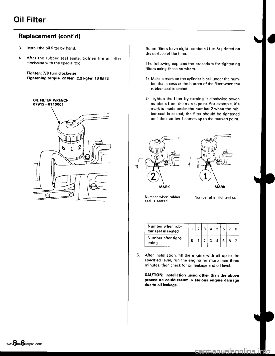
Installthe oil filter by hand.
After the rubber seal seats, tighten rhe oil filter
clockwise with the special tool.
Tighten: 7/8 turn clockwise
Tightening torque:22 N.m (2.2 kgt'm 16lbt.ft)
OIL FILTER WRENCH07912-61 10001
8-6
Some filters have eight numbers (1 to 8) printed on
the surface of the filter.
The following explains the procedure for tightening
filters using these numbers.
l) Make a mark on the cylinder block under the num-
ber that shows at the bottom of the filter when the
rubber seal is seated.
2) Tighten the filter by turning it clockwise seven
numbers from the makes point. For example, if a
mark is made under the number 2 when the rub-
ber seal is seated, the filter should be tightened
until the number 1 comes up to the marked point.
Number when rubberseal is seated.Number af ter tightening.
5.After installation. fill the engine with oil up to the
specified level, run the engine for more than threeminutes, then check for oil leakage and oil level.
GAUTION: Installation using other than the aboveprocedure could result in serious engine damage
due to oil leakage.
MARK
Number when rub-
ber seal is seated567IJ
Number after tight-
ening8123467
www.emanualpro.com
Page 199 of 1395
Inspection
1.
2.
Remove the timing belt (see section 6)
Turn the water pump pulley counterclockwise.
Check that it turns freely.
Check for signs of seal leakage.
NOTE: A small amount ol "weeping" from the bleed
hole is normal.
BIIED HOLE
Replacement
1. Remove the timing belt (see section 6).
2. Remove the water pump by removing five bolts
3, Inspect, repair and clean the O-ring groove and the
mating surface with the cylinder block.
Replace.6x1.0mm't2 N.m 11 2 kgf m.
8.7 tbf.ftl
4. lnstall the water pump in the reverse order of removal.
-
@-
I
I
10-1 1
www.emanualpro.com
Page 453 of 1395
Transmission Assembly
Disassembly
1. Remove the transfer assemblv.
O-RINGReplace.
Remove the shift arm cover assembly, and wiDe itclean of the sealant.
SHIFT ARM COVER ASSEMBLY
10 x 12 mm DOWEL ptN
13-14
3. Remove the interlock bolt.
SELECT ARM
SHIFT ARM SHAFT
Turn the select lever counterclockwise, then removethe shift arm A finger from the groove of the shiftforks.
Turn the shift arm shaft counterclockwise andremove the select arm finger from the groove of theshift arm A. then remove the shift arm shaft assem-blv.
Remove the vehicle speed sensor (VSS).
5.
6.
www.emanualpro.com
Page 505 of 1395

Mainshaft Thrust Clearance
Adjustment (cont'dl
-7. Slide the mainshaft base over the mainshaft.
Attach the mainshaft holder to the mainshaft as
follows:
NOTE:
. Back-out the mainshaft holder bolt and
loosen the two hex bolts.
. Fit the holder over the mainshaft so its lip is
towards the transmission.
. Align the mainshaft holder's lip around the
groove at the inside of the mainshaft
splines, then tighten the hex bolts.
MAINSHAFT HOLDERBOLT
MAINSHAFT EASE07GAJ - PG20130
-9. Seat the mainshaft fully by tapping its end with
a plastic hammer.
-10. Thread the mainshaft holder bolt in until it just
contacts the wide surface of the mainshaft
base.
07GAJ - PG20130
-8.
t--E-Hlf\f,A l\. xex
l"\y I aors
t____=__)"n-____"8
\
MAINSHAFTHOLDER07GAJ - PG20110
- 11. Zero a dial gauge onthe end ofthe mainshait.
-12. Turn the mainshaft holder bolt clockwise; stop
turning when the dial gauge has reached its
maximum movement, The reading on the dial
gauge is the amount of mainshaft end play.
NOTE: Turning the mainshaft holder bolt more
than 60 degrees after the needle of the dial
gauge stops moving may damage the transmis-
sion.
MAINSHAFT HOLDER07cru - PG20110
-13. lf the reading is within the standard, the clear-
ance rs correct.
lf the reading is not within the standard,
recheck the shim thickness.
Standard: 0.11 - 0.18 mm (0.00i1- 0.007 inl
DIAL GAUGEMAGNET STAND AASE07979 - PJ40001
www.emanualpro.com
Page 510 of 1395

22. Turn the select lever and shift arm shaft counter-
clockwise, then insert the shift arm shaft.
INTERLOCK EOLT39 N.m (4.0 kqt ft, 29 lbf ft)SELECT ARM
SHIFT ARM A
Align the shift arm A groove and select arm finger
by turn the shift arm shaft and select lever clock-
wise. then installthe shift arm shaft assembly.
Apply liquid gasket (P/N 08718 - 0001 or 08718 -
OO03) to the threads, then install the interlock bolt'
Apply liquid gasket to the surface of the shift arm
cover as snown.
Note these items:
. Use liquid gasket (P/N 08718 - 0001 or 08718 -
0003).
. Remove the dirtv oilfrom the sealing surface.
. Seal the entire circumference of the bolt holes to
prevent oil leakage.
. lf 20 minutes have passed after applying liquid
gasket. reapply it and assemble the housings.
a Allow it to cure at least 20 minutes after assem-
bly betore filling the transmission with MTF.
23.
-->.-
(
SHIFT ARM SHAFT
SHIFT ARM COVER ASSEMBLY
10 x 12 mft DOWEL PIN
t1
26. Install the shift arm cover assembly.
I x 1.25 mm27 N m 12.8 kgt m,20 lbf'ft)
Install the transfer assemblY.
NOTE: Lubricate MTF to the O-ring and contact
areas.
10 x 1.25 mm44 N.m 14.5 kgf.m, 33 lbl.ftl
13-71
www.emanualpro.com
Page 572 of 1395

Troubleshooting Procedures
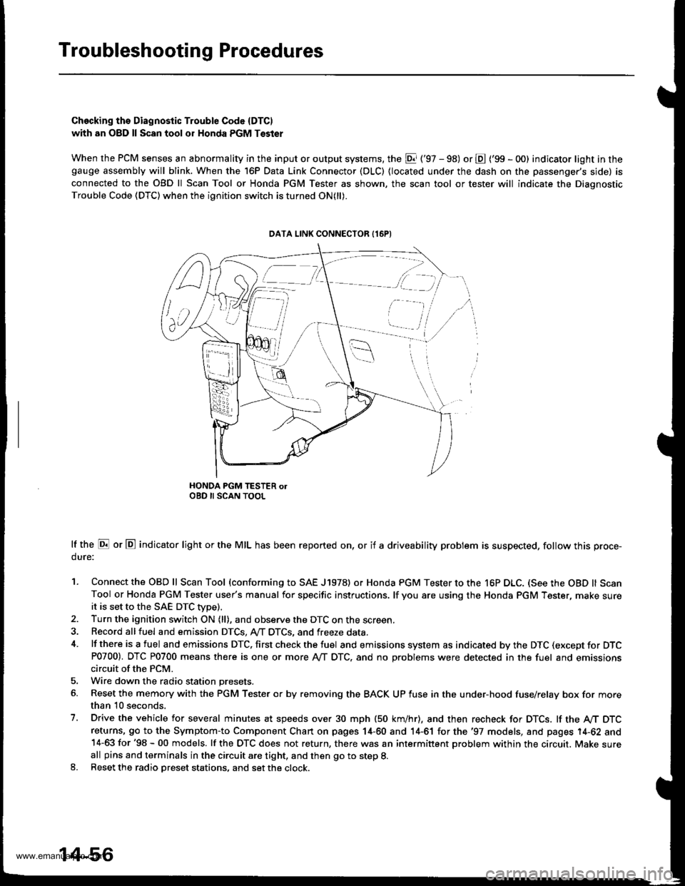
Checking ths Diagnostic Trouble Code (DTC)
with an O8D ll Scan tool or Honda PGM Tsster
When the PCM senses an abnormality in the input or output systems, the El ('97 - 98) or E ('99 - O0) indicator light in thegauge ass€mbly will blink. When the 16P Data Link Connector (DLC) {located under the dash on the passenger's side) is
connected to the OBD ll Scan Tool or Honda PGM Tester as shown, the scan tool or tester will indicate the Diagnostic
Trouble Code (DTC) when the ignition switch is turned ON(ll).
HONDA PGM TESTER olOBD II SCAN TOOL
lf the E or E indicator light or the MIL has been reported on, or if a driveability problem is suspected, follow this proce-
dure:
1. Connect the OBD ll Scan Tool (conforming to SAE J1978) or Honda PGM Tester to the 16P DLC. (See the OBD ll ScanTool or Honda PGM Tester user's manual for specific instructions. lf you are using the Honda PGM Tester, make sureit is set to the SAE DTC Wpe).2. Turn the ignition switch ON (ll), and observe the DTC on the screen
3. Record allfuel and emission DTCS, A,,/T DTCS, and freeze data.
4. lf there is a fuel and emissions DTC, first check the fuel and emissions system as indicated by the DTC (except for DTCP0700). DTC P0700 means there is one or more Ay'T DTC, and no Droblems were detected in the fuel and emissionscircuit of the PCM.
5. Wire down the radio station presets.
6. Reset the memory with the PGM Tester o. by removing the BACK UP fuse in the under-hood fuse/relay box for morethan 10 seconds.
7. Drive the vehicle for several minutes at speeds over 30 mph (50 km/hr), and then recheck for DTCS. lf the A/T DTCreturns, 9o to the Symptom-to Component Chart on pages 14-60 and 14-61 for the '97 models, and pages 14-62 and14-63 for '98 - 00 models. lf the OTC does not return, there was an intermittent problem within the circuit. Make sureall pins and terminals in the circuit are tight, and then go to step 8.8. Reset the radio Dreset stations, and set the clock.
DATA LINK CONNECTOR {16PI
[ -=.r,
ili,i /i,
v,., i
14-56
www.emanualpro.com
Page 575 of 1395
PCM Reset Procedure
'1. Turn the ignition switch off
2. Remove the BACK UP fuse (7.5 A) from the under-hood fuse/relay box for 10 seconds to reset the PCM.
NOTE:
. Disconnecting the BACK Up fuse also cancels the radio preset stations and clock setting Make note of the radio
presets before removing the fuse so you can reset them
. The PCM memorv can also be cleared by using the OBD ll Scan Tool or Honda PGM Tester'
UNDER.HOODFUSE/RELAY BOX
Final Proceduro
This procedure must be done after any troubleshooting.
1. Turn the ignition switch OFF.
2. Reset the PCM.
3. Disconnect the OBD ll Scan Tool or Honda PGM Tester from the Data Link Connector (16P), or remove the special tool
from the Service Check Connector (2P).
4. Turn the ignition switch ON (ll), and set the radio presets and clock setting'
5, To verify that the problem is repaired. test-drive the vehicle for several minutes at speeds over 30 mph (48 km/h).
BACK UP IRADIO} {7.5 AI FUSE
14-59
www.emanualpro.com