2000 HONDA CR-V dashboard
[x] Cancel search: dashboardPage 41 of 1395

Lubrication Points
For the details of lubrication points and type of lubricants to be applied. refer to the illustrated index and various work pro-
cedures (such as Assembly/Reassembly, Replacement, Overhaul, Installation, etc.) contained in each section.
Recomm6nded Engine OilEngine oil viscosity for ambient temperature ranges
100'F
-30 -20 .10 0 10 20 30 40'c
r1: Always use Genuine Honda Manual Transmission Fluid {MTF). Using motor oil can cause stiffer shifting because it
does not contain the orooer additives.*2: Always use Genuine Honda Premium Formula Automatic Transmission Fluid (ATF). Using a non-Honda ATF can affect
shift qualitv.+3r Always use Genuine Honda DOT 3 Brake Fluid. Using a non-Honda brake fluid can cause corrosion and decrease the
life of the system.*4: Always use Genuine Honda Power Steering Fluid. Using any other type of power steering fluid or automatic transmis-
sion fluid can caused increased wear and poor steering in cold weather.
API SERVICE LABEL
/,.*-G\
/.'z-\e\t/6AE\ll-;-1 5w-30 /---l
w
API CERTIFICATION SEAL
ffi-20 0 20
NO.LUBRICATION POINTSLUBRICANT
EngineAPI Service Grade: Use SJ "Energy Conserving" grade oil. The oilcontainer may also display the API Certitication seal shownbelow. Make sure it says "For Gasoline Engines." SAE vjscosity:See chart below.
2
TransmissionManualGenuine Honda MTF*1
AutomaticGenuine Honda Premium Formula Automatic Transmission Fluid(ATF)*'
3Rear differentialGenuine Honda CVT Fluid
4Brake line (includes ABS line)Genuine Honda DOT 3 Brake Fluid*3
5Clutch LineBrake fluid DOT 3 or DOT 4*3
6Shift lever pivots (Manual transmission)Grease with molybdenum disultide
1Release fork (Manual transmission)LJrea Grease UM264 P/N 4'1211 - PYs - 305
IPower steering gearboxSteering grease P/N 08733 - B070E
Throttle cable end {Dashboard lower panel holelSilicone grease
10l112
14
Throttle cable end (Throttle link)Brake master cylinder pushrodPedal linkageBattery terminalsFuelfill lidClutch master cylinder pushrod
Multi purpose grease
1617181920
Hood hinges and hood lockTailgate hingesHatch glass hingesDoor hinges, upper and lowerDoor opening detent
Honda White Lithium Grease
21
22
Caliper Piston seal, Dust seal,Caliper pin, PistonShilt cable and select cable {Manual transmission)Silicone grease
23Brake line ioints (Front and rear wheelhouse)Rust preventives
24Power steering systemGenuine Honda Power Steering Fluid-.
25Air conditioning compressorCompressor oil: SP 10 lP/N 38897 - P13 - A0lAH or38899-P13-A01)For Refrigerant: HFC 134a (R,134a)
3-2
www.emanualpro.com
Page 88 of 1395

Cruise Control
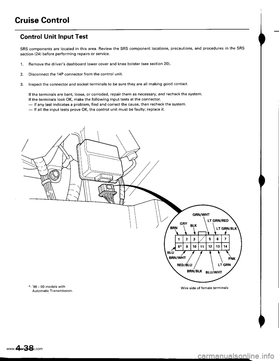
Control Unit Input Test
SRS components are located in this area. Review the SRS component locations. precautions, and procedures in the SRS
section (241 before performing repairs or seryice.
'1. Remove the driver's dashboard lower cover and knee bolster {see section 20).
2. Disconnect the 'l4P connector from the control unit.
3. Inspect the connector and socket terminals to be sure they are all making good contact
lf the terminals are bent, loose, or corroded, repair them as necessary, and recheck the system.
lf the terminals look OK, make the following input tests at the connector.- lf any test indicates a problem. find and correct the cause, then recheck the system.
- lf all the input tests prove OK, the control unit must be faulty; replace it.
*: '98 - 00 models withAutomatic Transmission.Wire side ol female terminals
4-38
www.emanualpro.com
Page 90 of 1395

Cruise Control
1.
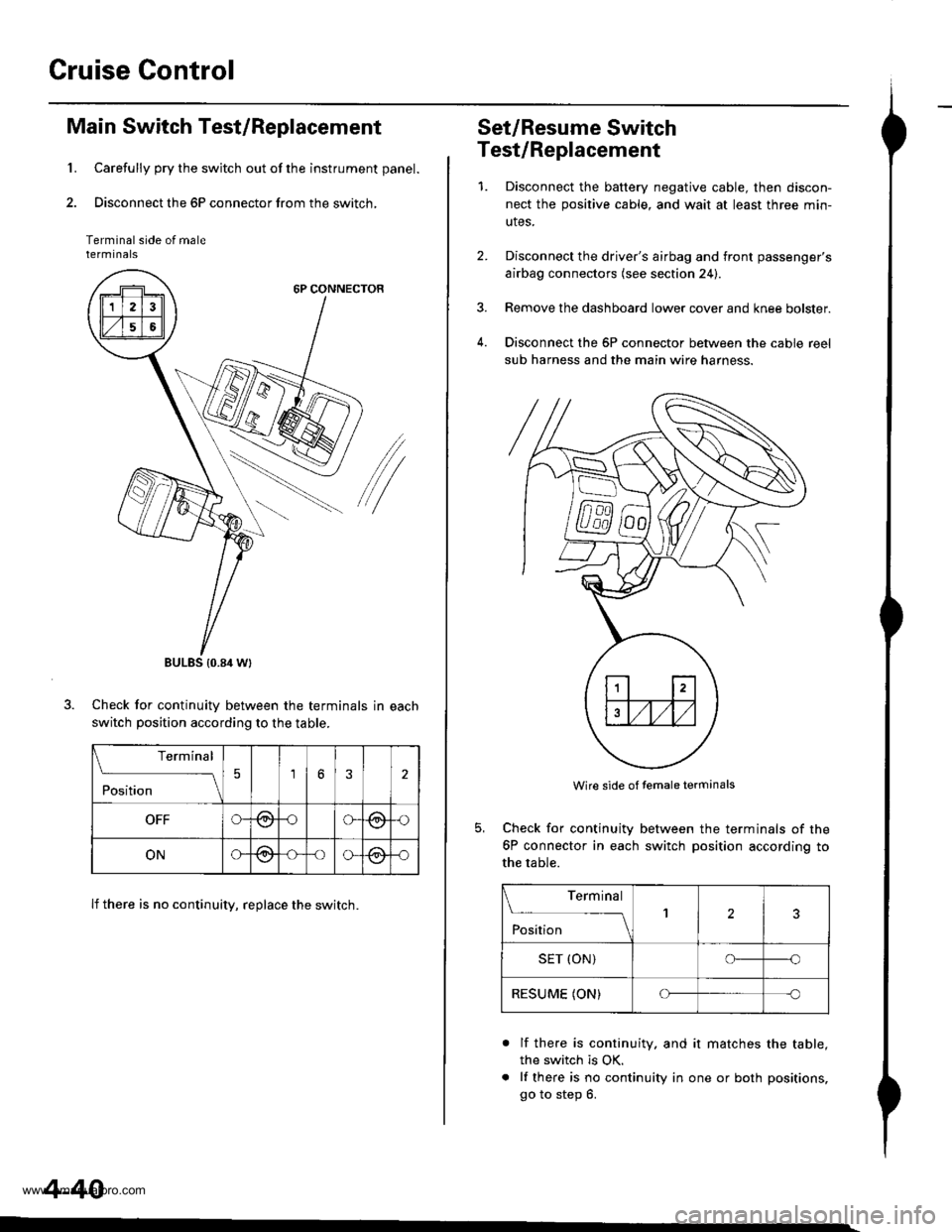
Main Switch Test/Replacement
Carefully pry the switch out of the instrument panel.
Disconnect the 6P connector from the switch,
Terminal side of malerermtnats
6P CONNECTOR
/
Check for continuitv between the terminals in each
switch position according to the table.
lf there is no continuity, replace the switch.
BULES {0.84 Wt
Terminal
;;;
-_\56
OFFG-@oG(9,{)
ONG@-oo-@-o
4-40
Set/Resume Switch
Test/Replacement
1.Disconnect the baftery negative cable, then discon-
nect the positive cable, and wait at least three min-
utes.
Disconnect the driver's airbag and front passenger's
airbag connectors (see section 24).
Remove the dashboard lower cover and knee bolster.
Disconnect the 6P connector between the cable reel
sub harness and the main wire harness.
4.
Wire side of temale terminals
Check for continuity
6P connector in each
the table.
between the terminals of the
switch position according to
Terminal
;;;
--_l2
SET (ON)o--o
RESUME (ON)Cf-c
a
lf there is continuity. and it matches the table,
the switch is OK.
lf there is no continuity in one or both positions,
go to step 6.
www.emanualpro.com
Page 242 of 1395
![HONDA CR-V 2000 RD1-RD3 / 1.G Workshop Manual
System Description
System Gonnectors lDash and Floor] -97 Model
MAIN WIREHARNESS
DASHBOARD WIREHANNESS
REAR HEATED OXYGENSENSOR SUA HARNESS
WIRE HARNESS
www.emanualpro.com HONDA CR-V 2000 RD1-RD3 / 1.G Workshop Manual
System Description
System Gonnectors lDash and Floor] -97 Model
MAIN WIREHARNESS
DASHBOARD WIREHANNESS
REAR HEATED OXYGENSENSOR SUA HARNESS
WIRE HARNESS
www.emanualpro.com](/manual-img/13/5778/w960_5778-241.png)
System Description
System Gonnectors lDash and Floor] -'97 Model
MAIN WIREHARNESS
DASHBOARD WIREHANNESS
REAR HEATED OXYGENSENSOR SUA HARNESS
WIRE HARNESS
www.emanualpro.com
Page 256 of 1395

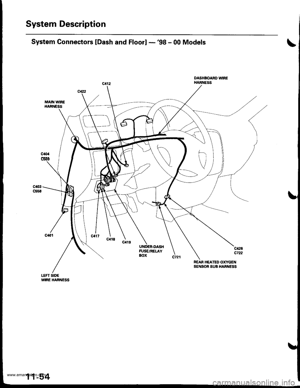
System Description
\System Connectors [Dash and Floorl -'98 - 00 Models
DASHBOARD WIREHART{ESS
REAR HEATED OXYGENSENSOR SUBHAR ESS
Ita|l{ wtREHARIIIESS
LEFT SIDEWIRE HAR ESS
11-54
www.emanualpro.com
Page 258 of 1395
![HONDA CR-V 2000 RD1-RD3 / 1.G Workshop Manual
System Description
System Connectors lDash and Floorl -98 - 00 Models (contd]
c510DASHBOARD WIREHARNESS
MAIN WIEEHARNESS
4: 99 - 00 models
1 1-56
www.emanualpro.com HONDA CR-V 2000 RD1-RD3 / 1.G Workshop Manual
System Description
System Connectors lDash and Floorl -98 - 00 Models (contd]
c510DASHBOARD WIREHARNESS
MAIN WIEEHARNESS
4: 99 - 00 models
1 1-56
www.emanualpro.com](/manual-img/13/5778/w960_5778-257.png)
System Description
System Connectors lDash and Floorl -'98 - 00 Models (cont'd]
c510DASHBOARD WIREHARNESS
MAIN WIEEHARNESS
'4: '99 - 00 models
1 1-56
www.emanualpro.com
Page 260 of 1395

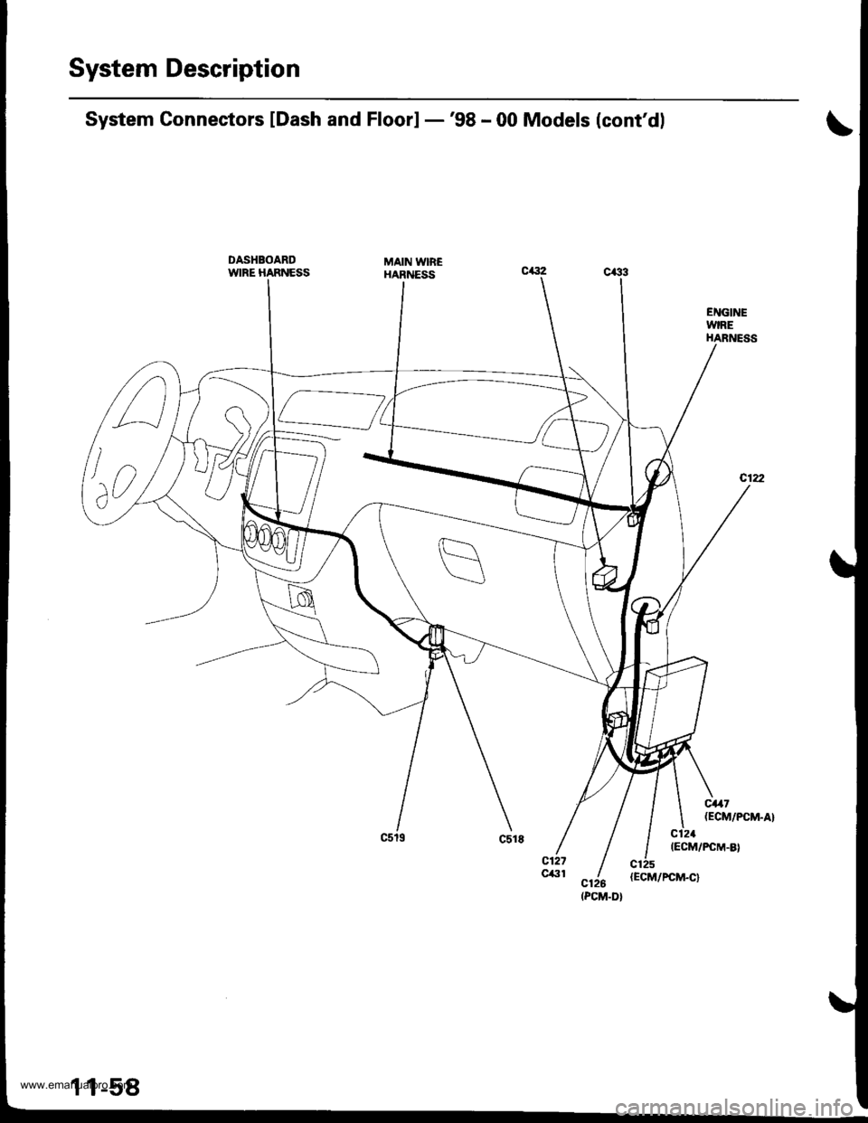
System Description
ENGINEWIREHARNESS
System Conneetors lDash and Floorl -'98 - 00 Models (cont'dl
DASHBOARDWIRE HARNESSMAIN WIB€HARNESS
c,47(ECM/PCM.A}
c121(ECM/PCM-8)
n
lno,
(PCM.D}
www.emanualpro.com
Page 519 of 1395

Description
General Operation
The Automatic transmission is a 3-element torque converter and triple-shaft electronically controlled unit which provides 4
speeds forward and 1 reverse speed The unit is positioned in line with the engine'
There are two tvoes of automatic transmission on CR-V; the four-wheel drive (4WD) model ('97 - 00)' and the front-wheel
drive (2WD) model ('98 - 00).
Toroue Converter, G€ars, and Clutches
The torque converter consists of a pump. turbine. and stator assembly in a single unit. The torque converter is connected to
the engine crankshatt. These parts turn together as a unit as the engine turns. Around the outside of the torque converter is
a ring gear which meshes with the starter pinion when the engine is started. The torque converter assembly serves as a fly-
wheel while transmitting power to the transmission mainshaft.
The transmission has three parallel shafts: the mainshaft. the countershaft, and the sub-shaft. The mainshaft is in line with
the engine crankshaft. The mainshaft includes the 1st, 2nd. and 4th clutches, and gears lor 3rd,2nd,4th. reverse and 1st
(3rd gear is integral with the mainshaft, while reverse gear is integral with the 4th gear). The countershaft includes the 3rd
clutch and gears for 3rd,2nd, 4th, reverse, 1st, and park. Reverse and 4th gears can be locked to the countershaft at its cen-
ter, providing 4th gear or reverse, depending on which way the selector is moved. The sub-shaft includes the lst-hold
clutch and gears for lst and 4th.
The gears on the mainshaft are in constant mesh with those on the countershaft and sub-shaft. When certain combinations
of gears are engaged by the ctutches, power is transmitted from the mainshaft to the countershaft to provide E, D!, tr, tr,
and E position ('97 - 98 models). and E. E, E, and E position ('99 - 00 models)'
Electlonic Control
The electronic controt system consists of the Powenrain Control Module (PCM), sensors, a linear solenoid, and four
solenoid valves. Shifting and lock-up are electronically controlled for comfortable driving under all conditions. The PCM is
located below the dashboard, under the kick panel on the passenger's side.
Hydraulic Control
The valve bodies include the main valve body, the secondary valve body, the regulator valve body, the servo body, and
the lock up valve body. They are bolted to the torque converter housing. The main valve body contains the manual valve,
the 1-2 shift valve, the 2nd orifice control valve. the CPB {Clutch Pressure Back-up) valve, the modulator valve, the servo
control valve. the relief valve, and ATF pump gears. The secondary valve body contains the 2-3 shift valve, the 3-4 shift
valve, the 3,4 orifice control valve. the 4th exhaust valve and the CPC (Clutch Pressure Control) valve. The regulator valve
bodv contains the pressure regulator valve, the torque converter check valve, the cooler relief valve, and the lock-up con-
trol valve. The servo body contains the servo valve which is integrated with the reverse shift tork, and the accumulators
The lock-up valve body contains the lock-up shift valve and the lock-up timing valve. The linear solenoid and the shift con-
trol solenoid valve Ay'B are bolted to the outside of the transmission housing, and the lock-up control solenoid valve Ay'B is
bolted to the outside of the torque converter housing. Fluid trom the regulator passes through the manual valve to the
various control valves. The clutches receive fluid from their respective feed pipes or internal hydraulic circuit
ShiftControl Mechanism
input from various sensors located throughout the vehicle determines which shift control solenoid valve the PCM will acti-
vate. Activating a shift control solenoid valve changes modulator pressure, causing a shift valve to move. This pressurizes
a line to one of the clutches. engaging that clutch and its corresponding gear. The shift control solenoid valves A and B are
controlled by the PCM.
Lock-up Mechanism
tn E! position (,97 - 98 modets) and in E position ('99 - O0 models), in 3rd and 4th, and in Del position in 3rd ('97 - 98
models) and in El position with Over,Drive (O/D) is OFF (by pressing rhe O/D switchl in 3rd ('99 - 00 models), pressurized
fluid is drained from the back of the torque converter through a fluid passage, causing the lock-up piston to be held
against the torque converter cover, As this takes place, the mainshaft rotates at the same speed as the engine crankshaft.
Together with hydraulic control, the PcM optimizes the timing of the lock-up mechanism The lock-up valves control the
range of lock-up according to lock-up control solenoid valves A and B, and the linear solenoid. When lock-up control
solenoid valves A and B activate, the modulator pressure changes. The lock-up control solenoid valves A and B and the
linear solenoid are controlled by the PCM.
{cont'd)
14-3
www.emanualpro.com