Page 1037 of 2189
Driveshafts
Removal (cont'd)
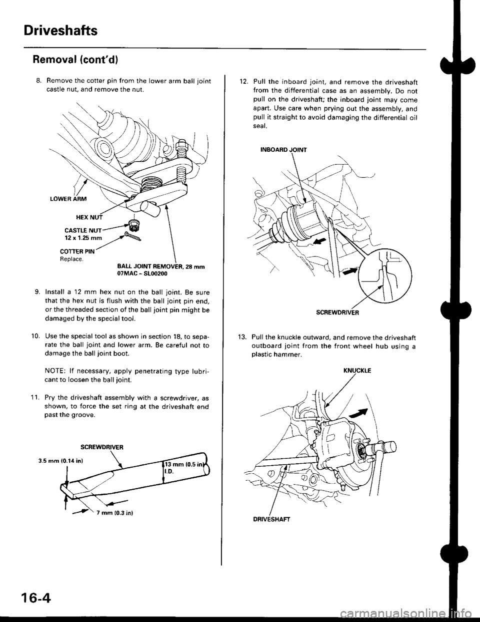
8. Remove the cotter pin from the lawer arm ball joint
castle nut. and remove the nut.
Install a 12 mm hex nut on the ball joint. Be sure
that the hex nut is flush with the ball joint pin end,
or the threaded section of the ball joint pin might be
damaged by the special tool.
Use the special tool as shown in section 18, to sepa-
rate the ball joint and lower arm. Be careful not to
damage the ball joint boot.
NOTE: lf necessary, apply penetrating type lubri,
cant to loosen the ball joint.
Pry the driveshaft assembly with a screwdriver, as
shown, to force the set ring at the driveshaft endpast the groove.
10.
11.
3.5 mm
07MAC - SL00200
SCREWDRIVER
16-4
12. Pull the inboard joint, and remove the driveshaft
from the differential case as an assembly. Do notpull on the driveshaft; the inboard joint may come
apart. Use care when prying out the assembly, andpull it straight to avoid damaging the differential oil
seat.
13. Pull the knuckle outward, and remove the driveshaft
outboard joint from the front wheel hub using aplastic hammer.
SCREWDRIVER
DRIVESHAFT
Page 1046 of 2189
l.
11. Set the double loop band onto the boot and dynam-
ic damper with the band end toward the front ot the
vehicle.
LOOP BANO
Pull up the slack in the band bY hand
Mark a position on the band 10 - 14 mm {0 4 - 0 6
in) from the cliP.
DOUBLE
,
1')
13.
CLIP
Ip
14.
15.
Thread the free end of the band through the nose
section of the boot band tool and into the slot on
the winding mandrel.
Place a wrench on the winding mandrel of the boot
band tool, and tighten the band until the mark you
made on the band meets the edge of the clip.
Mark on band.
Lift up the boot band tool to bend the free end
the band 90 degrees, then center-punch the clip'16.
(cont'd)
16-13
(KD-3191 or equivalent)
HAMMER
Page 1050 of 2189
I
13. Fit the boot ends onto the driveshaft and the
outboard joint
Fit the double loop boot bands onto the boot ends'
Pull up the slack in the band by hand'
Mark a position on the band 10 - 14 mm {0 4 - 0 6
in,) from the cliP.
14.
16.
CLIP
lrz
17. Thread the free end of the band through the nose
section of a commercially avaiiable boot band tool
KD-3191 or equivalent and into the slot on the wind-
ing mandrel.
BOOT BAND TOOL
lCommerciallY available)
KD-3191 or equivalent
MANDREL
Place a wrench on the winding mandrel of the boot
band tool, and tighten the band until the marked
spot on the band meets the edge of the clip'
Lift uo the boot band tool to bend the free end of
the band 90" to the clip Center punch the clip, then
fold over the remaining tail onto the clip
Mark spot.
18.
1q
(cont'd)
16-17
Page 1052 of 2189
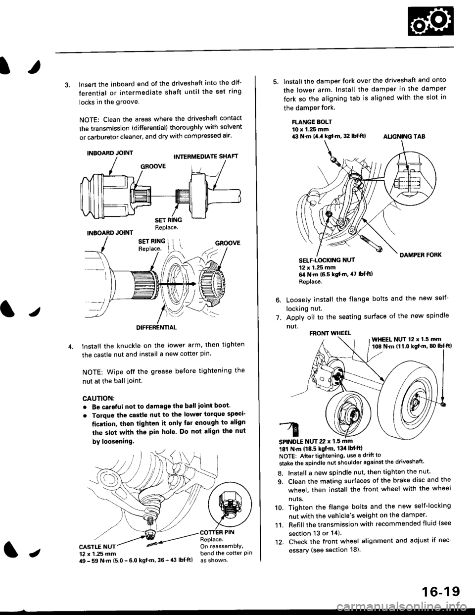
3. lnsert the inboard end of the driveshaft into the dif-
terential or intermediate shaft until the set ring
locks in the groove
NOTE: Clean the areas where the driveshaft contact
the transmission (differential) thoroughly with solvent
or carburetor cleaner, and dry with compressed air'
INBOARD JOINT
INBOARD JOINTReplace.
GROOVE
an
DIFFERENTIAL
lnstall the knuckie on the lower arm. then trghten
the castle nut and install a new cotter pin
NOTE: wipe off the grease before tightening the
nut at the ball ioint.
CAUTION:
. Be careful not to damago the ball ioint boot'
. Torque the castle nut to the lower torque sp€ci-
fication, thsn tighten it only far enough to align
the slot with th€ pin hol6. Do not align the nut
by loosening.
CASTLE NUT12 x 1 .25 mm
COTTER PINReplace.On reassemblY,bend the cotter pinJi$ - 59 N.m 15.0 - 6.0 kgl m,35 - 43 lbf ftl
16-19
5. lnstall the damper tork over the driveshaft and onto
the lower arm. Install the damper in the damper
fork so the aligning tab is aligned with the slot in
the damPer fork.
FLANGE BOLTl0 r 1.25 mmrit N.m t4.a kgf.m, 32 lbf.ft) AIIGN|NG TAB
1.
SELF-LOGKING NUT12 x 1.25 mm6,1N.m 16.5 kgi.m, a7 lbfftl
Replace.
Loosely install the flange bolts and the new self-
locking nut.
Apply oil to the seating surface of the new spindle
nut.
181 N m 118.5 kgt'm, 13il lbt'ftl
NOTE: Aftortightening, use a drift to
stake the spindle nut shoulder against the drivoshaft'
8. Install a new spindle nut, then tighten the nut'
9. Clean the mating surfaces ot the brake disc and the
wheel. then install the front wheel with the wheel
nuts.
10. Tighten the flange bolts and the new self-locking
nut with the vehicle's weight on the damper.
11. Refill the transmission with recommended fluid (see
section 13 or 14).'t2. Check the front wheel alignment and adjust if nec-
essary (see section 18),
FRONT WHEEL
SPINDLE NUT 22 x 1.5 mm
WHEEL NUT 12 x 1.5 mm108 N.m (11.0 kgl'm, g) lbl ftl
Page 1053 of 2189
Intermediate Shaft
Removal
Drain the transmission oil or fluid {see section 13 or
r 4).
Remove the left driveshaft (see page 16-3).
Remove the three dowel bolts.
OOWEL BOLTS'10 x 1.25 mm
Remove the intermediate shaft from the differential.
CAUTION: Hold the intermsdiate shaft horizontal
until it is clear of lhe dilterential to prevent damage
to the differential oil seal.
'1.
2.
3.
INTERMEDIATE SHAFT
16-20
Disassembly
NOTE: Be careful not to damage the metal rings on theintermediate shaft during disassembly.
1. Remove the set ring.
2. Remove the intermediate shaft outer seal from theDeaflng suppon.
3. Remove the external circlip,
Page 1057 of 2189
l.
t
Steering
Speciaf Tools ....."'.....17-2
Manual Steering
Component Locations
lndex ................ ....... 17-3
Inspection and Adiustment
Steering Operation "'......"............... 17-4
Rack Guide Adiustment ................... 17-5
*Steering Wheel
(See power steering section)
*Steering Column
(See power steering sectionl
Steering Gearbox
Removal ................. 17-5
Disassembly ......."" 17-7
ReassemblY ..'......... 17-9
lnstallation ............. 17-13
Power Steering
Component Locations
lndex "......."..... """' 17-15
System DescriPtion
Fluid Flow Diagram .........""............. 17'16
Steering Pump ............'... "........"'...-- 17 -17
Steering Gearbox .".................'...'.'.' 17-20
Troubleshooting
Generaf Troubleshooting ..........--.... 17'22
Noise and Vibration ......................... 17 -26
Ffuid Leaks .............17-28
Inspection and Adiustment
Steering Operation'......."'........'...... 1 7-30
Power Assist Check
With Vehicle Parked .."................ 17-30
Steering Linkage and Gearbox ....." 17-31
Pump Beft ...--.""".. 17-32
Rack Guide Adiustment .'.......'.......'. 17'33
Fluid Replacement .....'.."................. 17-33
Pump Pressure Check .............'....-. " 17 -34
'Steering Wheel
Removal .."'........'... 17-35
lnstallation ............. 17-35
Disassembly/Reassembly ......'.....'.' 17-36
*Steering Column
Removal/lnstallation ....'........... ---.... 17'37
lnspection .............. 17'38
Power Steering Hoses, Lines
Fluid Leakage Inspeetion ............'.... 17-39
Replacement ......".. 17-39
Power Steering PumP
Removal/lnstallation .'.'..'..'............. 17-40
Disassembly ".........17-41
fnspection .......---'." 17'42
Reassembly ..'.........17-44
Steering Gearbox
Removal ....'........."' 17'47
DisassemblY ..........' 17-49
Reassembly '........... 17-55
lnstallation ............. 17-65
Ball Joint Boot Replacement .......'.. 17-68
Ir/
lp
Page 1059 of 2189
Component Locations
tlndex
Manual Steering
NOTE:
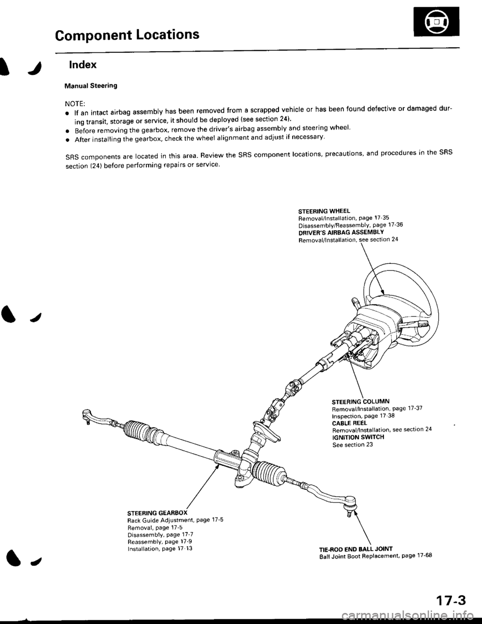
. lf an intact airbag assembly has been removed from a scrapped vehicle or has been found defective or damaged dur-
ing transit. storage or service, it should be deployed (see section 24)'
o Before removing the gearbox, remove the driver's airbag assembly and steering wheel
. After insta lling the gearbox, check the wheel alignmentand adjust if necessary
SRS components are located in this area. Review the SRS component locations, precautions, and procedures in the SRS
section 124) before performing repairs or service'
STEERING WHEELRemoval/lnstallation, Page 17'35
Disassembly/FeassemblY, page 17-36
DRIVER'S AIRBAG ASSEMBLY
Removal/lnstallation, see section 24
STEERING COLUMNRemoval/lnstallation, Page 17-37
Inspection, page 17'38
CABLE REELRemoval/lnstallation, see section 24
IGNTTION SWITCH
See section 23
STEERING GEARBOXRack Guide Adiustment, Page 17-5
Removai, page 17'5Disassembly, Page 17_7Reassembly, page 17_9Installation, page 17 13TIE.ROD END BALL JOINT
Ball Joint Boot Replacement, page 17-68
J
t,
17-3
Page 1061 of 2189
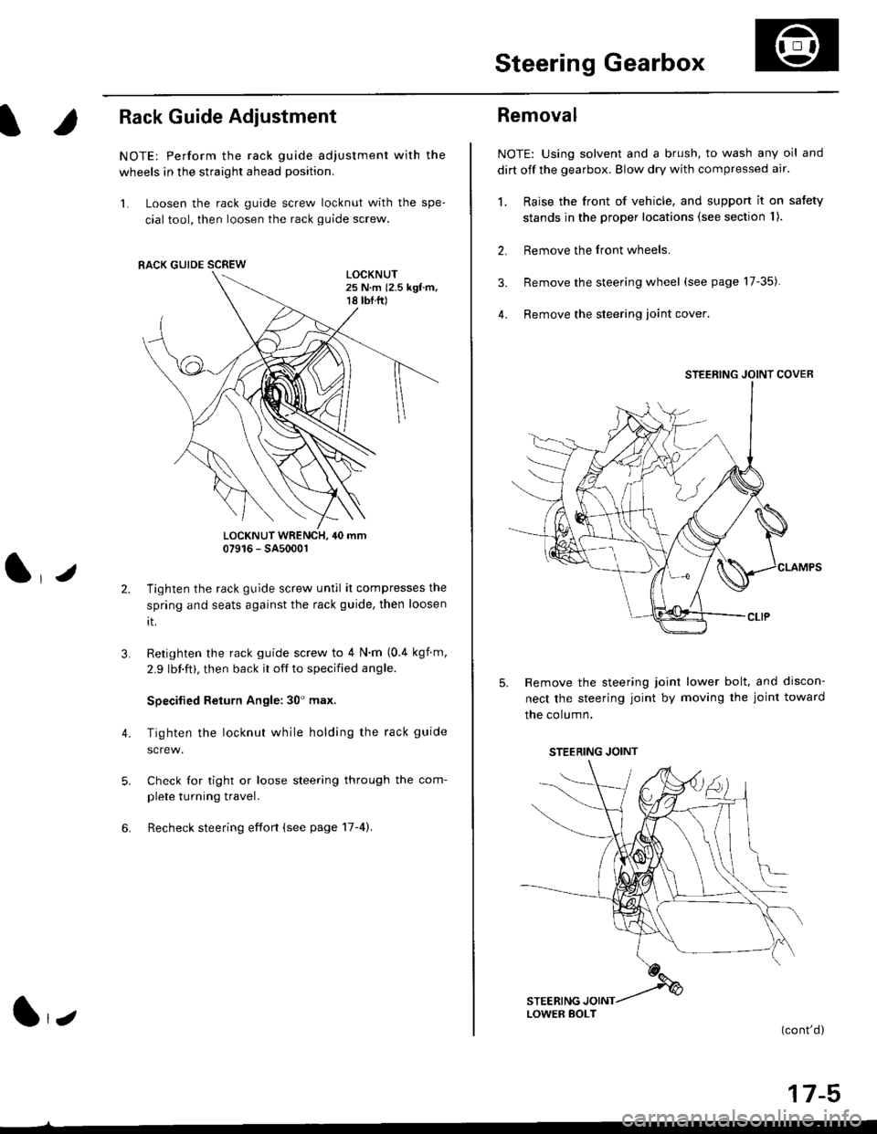
Steering Gearbox
l.r
Rack Guide Adjustment
NOTE: Perform the rack guide adjustment with the
wheels in the straight ahead position.
1. Loosen the rack guide screw locknut with the spe-
cial tool, then loosen the rack guide screw.
LOCKNUT WRENCH, 40 mm07916 - SA5000r
Tighten the rack guide screw until it compresses the
spring and seats against the rack guide, then loosen
rt.
Retighten the rack guide screw to 4 N'm (0.4 kgf m,
2.9 lbf.ft), then back it off to specified angle.
Specilied Return Angle: 30' max.
Tighten the locknut while holding the rack guide
Check for tight or loose steering through the com-
plete turning travel.
Recheck steering effort (see page 17-4).
4.
RACK GUIDE SCREW
l,z
Removal
NOTE: Using solvent and a brush, to wash any oil and
dirt off the gearbox. Blow dry with compressed air.
1. Raise the front of vehicle, and support it on satety
stands in the proper locations (see section I ).
2. Remove the front wheels.
3. Remove the steering wheel (see page 17-35).
4. Remove the steering loint cover
Remove the steering joint lower bolt, and discon-
nect the steering joint by moving the joint toward
the column.
(cont'd)
17-5
STEERING JOINT COVER
LOWER BOLT
STEERING JOINT