2000 HONDA CIVIC Connecting rods
[x] Cancel search: Connecting rodsPage 198 of 2189
Engine Block
Speciaf Tools ..........." 7-2
lllustlated Index ...................."..'.......... 7-3
Flywheel and Drive Plate
Repf acement """'.' 7-7
Connecting Rod and Crankshaft
End Play ..........."....7-8
Main Bearings
Clearance ............... 7-9
Selection ................7-10
Connecting Rod Bearings
clearance ....'.......... 7-11
Selection ................ 7-11
Pistons and Crankshaft
Removaf ................. 7 -12
Crankshaft
Inspection ."".........7-14
Pistons
Inspection ......"'.....7-15
fnstaffation .............7-23
Cylinder Block
lnspec'tion ..............7-16
Bore Honing ..........7-17
Piston Pins
Removal ...,...........'.7-17
lnstallation .............7-18
Inspection .'............7-19
Connecting Rods
Selection ................7-18
Piston Rings
End Gap ..........".."' 7'2O
Repfacement .........7-2O
Ring-to-Groove Clearance ...........'.'. 7 -21
Afignment .......""'.. 7'21
Crankshaft Oil Seal
fnstaffation .............7-22
Crankshaft
fnstaffation ..-.-..'.".' 7'23
Oil Pan
lnstallation .............7-26
Oil Seals
fnstaffation ....""""' 7-29
r-f
Page 210 of 2189
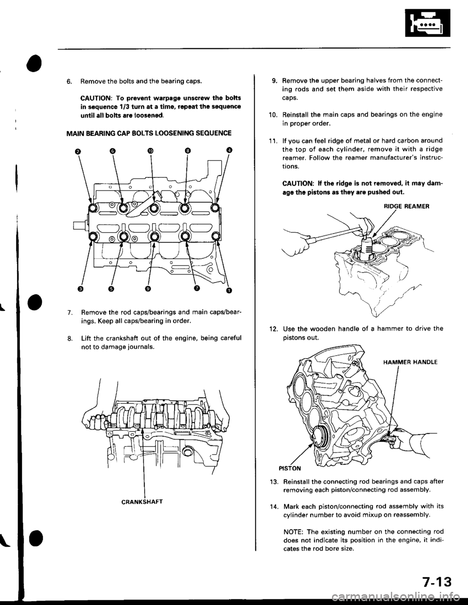
6. Remove the bolts and the bearing caps.
CAUTION: To prevenl warpago unscrow lhe bolts
in s€quence 1/3 turn at a tims, r€paat the soquence
until all bolts ar€ loo3ened.
MAIN BEARING CAP BOLTS LOOSENING SEOUENCE
Remove the rod caps/bearings and main capvbear-
ings. Keep all caps/bearing in order.
Lift the crankshaft out of the engine, being careful
not to damage journals.
7.
S:_]ILOJLOAO
CRANKSHAFT14.
7-13
qRemove the upper bearing halves from the connect-
ing rods and set them aside with their respective
caos.
Reinstall the main caps and bearings on the engine
in proper order,
lf you can feel ridge of metal or hard carbon around
the top of each cylinder, remove it with a ridge
reamer. Follow the reamer manufacturer's instruc-
I|ons.
CAUTION; lf the ridge is not removed, it may dam-
age tho pistons as they are pushod out.
RIOGE REAMER
10.
11.
12.Use the wooden handle of a hammer to drive the
pastons out.
13.Reinstall the connecting rod bearings and caps after
removing each piston/connecting rod assembly.
Mark each piston/connecting rod assembly with its
cylinder number to avoid mixup on reassembly.
NOTE: The existing number on the connecting rod
does not indicate its position in the engine, it indi-
cates the rod bore size.
Page 215 of 2189
Connecting RodsPiston Pins
Selection
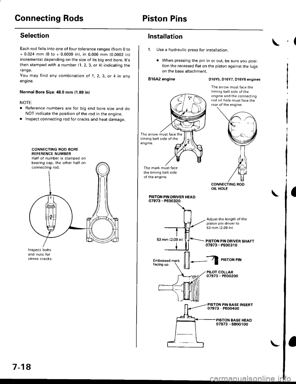
Each rod falls into one of four tolerance ranges {from O to+ 0.024 mm (0 to + 0.0009 in), in 0.006 mm (0.0002 in)increments) depending on the size of its big end bore. lt,sthen stamped with a number {1, 2,3, or 4) indicating therange.
You may find any combination ot l, 2, 3, or 4 in any
engrne.
Normal Eore Size: 48.0 mm (1.89 in)
NOTE:
o Reference numbers are for big end bore size and doNOT indicate the position of the rod in the engine.. Inspect connecting rod for cracks and heat damage.
CONNECTING ROD AOREREFERENCE NUMBERHalf of number is stamped onbearing cap, the other half onconnectrng rod.
7-18
Installation
1. Use a hydraulic press for installation.
. When pressing the pin in or out, be sure you posi
tion the recessed flat on the piston against the lugson the base attachment.
816A2 engine
The arrow must face thetiming belt side of theeng Ine.
The mark must facethe timing belt sideof the engine.
D16Y5, D16Y7, O16Y8 engines
The arrow must face thetiming belt side o{ theengine and the connectingrod oil hole must face therear of the engine.
Adjust the length of thepiston pin driver to53 mm (2.09 4n)
PISTON PIN DRIVER SHAFT07973-PEOo3r0
PISTON PIN DRIVER HEAD
il--Z
P,"roNPrN
PILOT COLLAR07973-PE00200
PISTON PIN BASE INSERT07973 PEO0400
PISTON EASE HEAO07973 -5800100
,(
a
Page 220 of 2189
PistonsGrankshaft
lnstallation
Before installing the pistons, apply a coat of
engine oil to the ring grooves and cylinder
bores.
lf the crankshaft is already installed:
. Set the crankshaft to BDC for each cylinder.
. Remove the connecting rod caps, and slip short
sections of rubber hose over the threaded ends
of the connecting rod bolts.
. lnstall the ring compressor. check that the bear-
ing is securely in place, then position the piston
in the cylinder, and tap it in using the wooden
handle of a hammer.
o Stop after the ring compressor pops free, and
check the connecting rod-to-crank journal align-
ment before pushing the piston into place
. Apply engine oil to the bolt threads. Install the
rod caps with bearings, and torque the nuts to:
815A2 engine:
40 N.m {,1.1 kgf.m, 30 lbf'ft|
D16Y5, D16Y7, D16Y8 engines:
31 N.m (3.2 kgf'm,23 lbf'ft)
lf the crankshaft is not installed:
. Remove the rod caps and bearings, install the ring
compressor, then position the piston in the cylin-
der, and tap it in using the wooden handle of a
hammer.
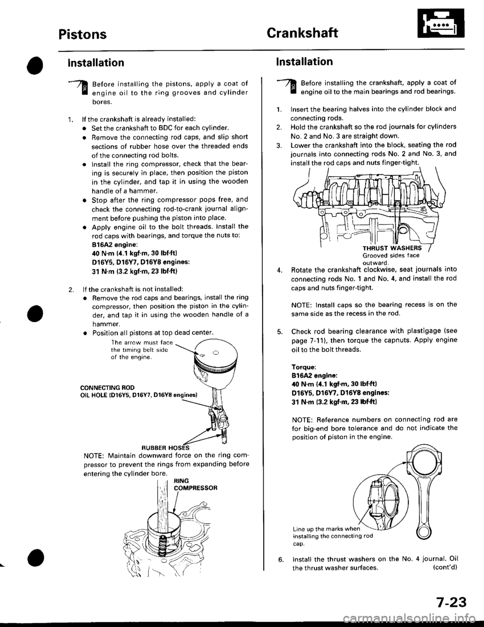
. Position all Distons at top dead center.
1.
2.
The arrcw must facethe taming belt sideof the engine.
CONNECTING ROOOIL HOLE lD16Y5, D16Y7, D16YB ongines)
NOTE: Maintain downward force on the ring com-
pressor to prevent the rings from expanding before
entering the cylinder bore.
RUBBER
,lll
lnstallation
Before installing the crankshaft, apply a coat of
engine oil to the main bearings and rod bearings.
Insert the bearing halves into the cylinder block and
connecting rods.
Hold the crankshaft so the rod journals for cylinders
No.2 and No. 3 are straight down.
Lower the crankshaft into the block, seating the rod
journals into connecting rods No. 2 and No. 3, and
install the rod caps and nuts finger-tight.
1.
2.
3.
5.
Grooved sides faceoulward.Botate the crankshaft clockwise, seat journals into
connecting rods No, 1 and No.4, and install the rod
caps and nuts finger-tight.
NOTE: Install caps so the bearing recess is on the
same side as the recess in the rod.
Check rod bearing clearance with plastigage (see
page 7-11), then torque the capnuts. Apply engine
oil to the bolt threads.
Torque:
816A2 sngine:/l{, N.m {a.l kgf.m, 30 lbf'ftl
D16Y5, D16Y7, Dl6Y8 engines:
31 N.m (3.2 kgf.m, 23 lbf'ft|
NOTE: Reference numbers on connecting rod are
for big-end bore tolerance and do not indicate the
position of piston in the engine.
Line up the marks wheninstalling the connectrng rod
cap.
6. Install the thrust washers on the No. 4 journal. Oil(cont'd)
7-23
the thrust washer surfaces,
Page 1070 of 2189
Steering Gearbox
Installation (cont'dl
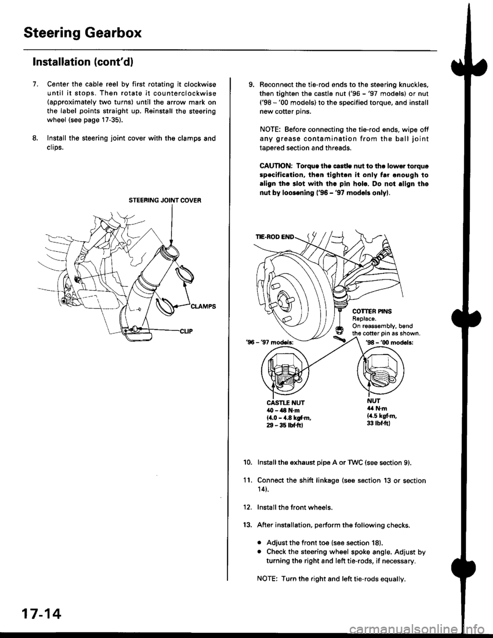
Center the cable reel by first rotating it clockwise
until it stops. Then rotate it counterclockwise(approximately two turns) until the arrow mark on
the label points straight up. Reinstall the steering
wheel (see page 17-35).
Install the steering joint cov€r with the clamps and
clrps.
7.
STEERING JOINI COVER
17-14
9. Reconnsct the ti€-rod ends to the steering knuckles,
thon tightsn th€ castle nut ('96 -'97 models) or nut('98 -'00 models) to the specified torque, and install
new cotter pins.
NOTE: Before connecting the tie-rod ends, wipe off
any grease contamination from the ball joint
tapered section and threads.
CAUTION: Torque lhe ct3tle nut to thr lowsr torque
spocification, th€n tighton it only tar anough to
align the 3lot with tho pin hob. Do not align the
nut by loosening ('96 - '97 modcls onlyl.
TIE.ROD
COTTER PINSR6plac6.On rgassombly, b6nd
'96 - 37 model3:
cotter prn as shown.'98 - '00 modol3:
NUT4a N.m(4.5 kgf.m,33 lbr.ftl
CAST1T NUT,O - ilt N'm{4,0 - 4.8 kgf.m.29 - 35 tbtftl
10.Installthe exhaust pipe A or TWC (see section 9).
Connect the shift linkage (see section 13 or section
14).
Install the front wheels.
After installation, perform the following checks.
. Adjust the front toe (see section 18).. Check the steering wheel spoke angle. Adjust by
turning the right and left tie-rods, if necessary.
NOTE: Turn the right and left tie-rods equally.
ll.
Page 1123 of 2189
)
1?
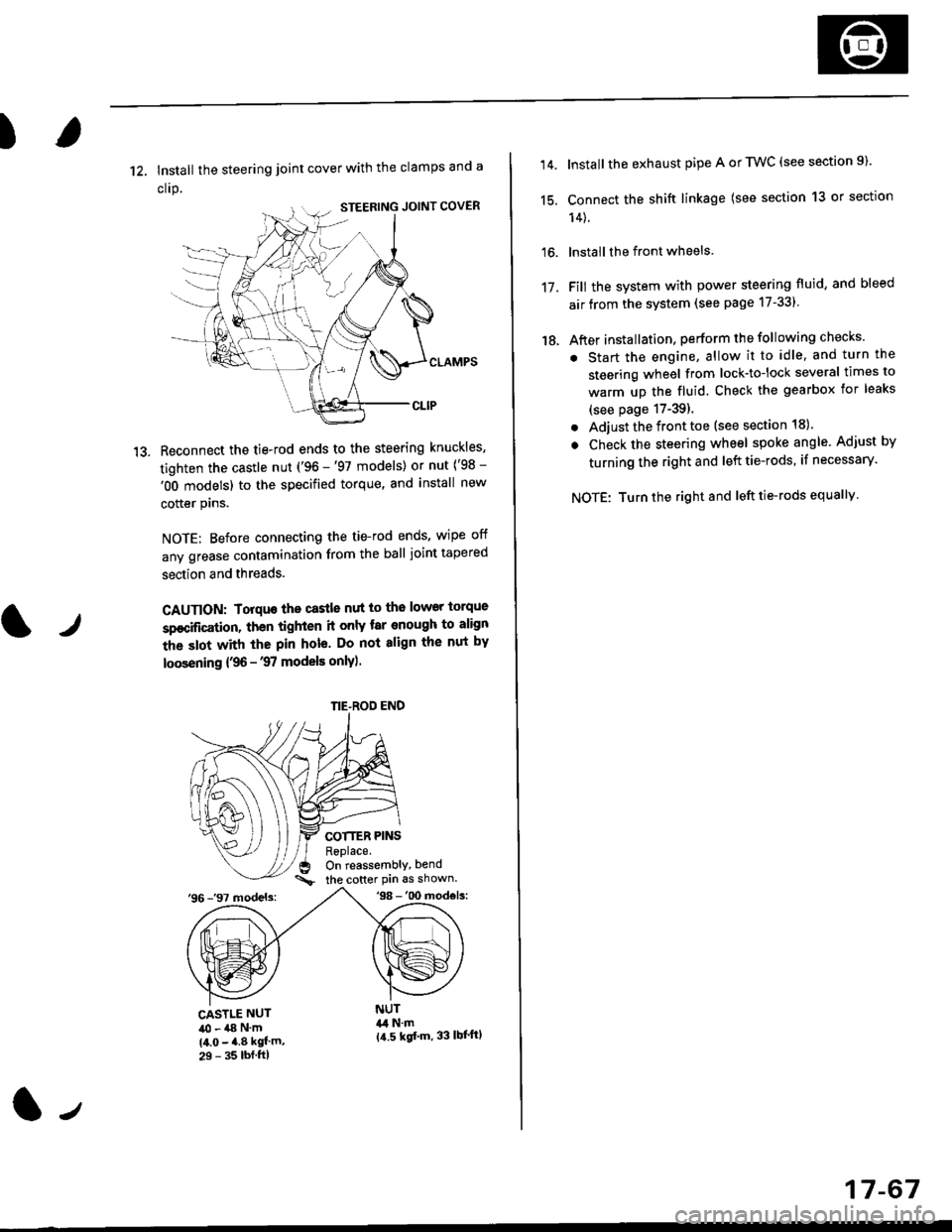
12, Install the steering joint cover with the clamps and a
clrp.
Reconnect the tie-rod ends to the steering knuckles,
tighten the castle nut ('96 -'97 models) or nut ('98 -
'OO models) to the specified torque, and install new
cotter plns.
NOTE: Before connecting the tie-rod ends, wipe off
any grease contamination from the ball joint tapered
section and threads.
CAUTION: Torquo the castle nut to the lower torque
sp€cification, then tighten it only tar enough to align
the slot with the pin hole. Do not align the nut by
loosening {,96 -'97 models only).
COTTER PINSReplace.On reassembly, bend
the cotter Pin 6s shown.'96 -'97 models:'98 -'00 mod€ls:
tr
CASTLE NUT40 - a8 N'm(4.0 - 4.8 kgf'm,29 - 35 lbf.ftl
NUT&l N.m{a.5 kgf'm, 33 lbl'ftl
NE-ROD END
(l-,
17-67
14.
15.
16.
17.
18.
Install the exhaust pipe A or TWC (see section 9).
Connect the shift linkage (see section 13 or section
14).
lnstall the front wheels
Fill the system with power steering fluid, and bleed
air from the system (see page 17-331
After installation, perform the following checks
. Start the engine, allow it to idle, and turn the
steering wheel from lock-tolock several times to
warm up the fluid. Check the gearbox for leaks
(see page 17-39).
. Adjust the front toe (see section 18).
. Check the steering wheel spoke angle. Adjust by
turning the right and left tie-rods, if necessary.
NOTE: Turn the right and left tie-rods equallv
Page 1750 of 2189
Precautions/Procedu res
Steering-related Precautions
Stesring Wheel and Cable Reol Alignment
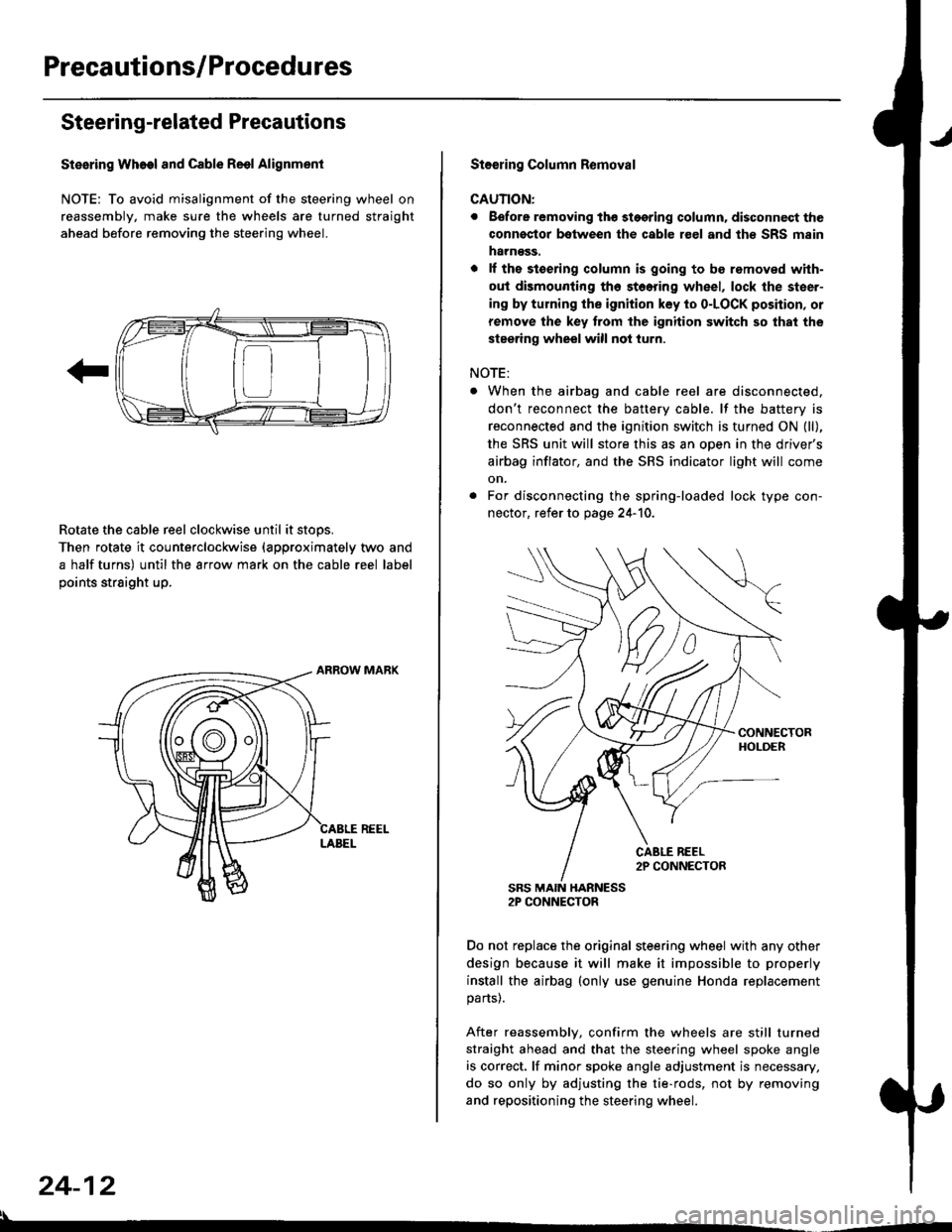
NOTE: To avoid misalignment of the steering wheel on
reassembly, make sure the wheels are turned straight
ahead before removing the steering wheel.
Rotate the cable reel clockwise until it stops.
Then rotate it counterclockwise {approximately two and
a half turns) until the arrow mark on the cable reel label
points straight up.
24-12
:l
St€€rin9 Column Removal
CAUTION:
. Eefore removing thg stggring column. disconnect the
connsstor bqtween the cable r€el and th€ SRS msin
harness.
. lf the stoering column is going to be romoved with-
out dismounting th6 stoering wheel, lock the steer-
ing by turning the ignition key to o-LOCK position, or
remove the key trom the ignition switch so that the
steering wheel will not turn.
NOTE:
When the airbag and cable reel are disconnected,
don't reconnect the battery cable. lf the battery is
reconnected and the ignition switch is turned ON (ll),
the SRS unit will store this as an open in the driver's
airbag inflator, and the SRS indicator light will come
on.
For disconnecting the spring-loaded lock type con-
nector, refer to page 24-'10.
SRS MAIN HARNESS2P CONNECTOR
Do not replace the original steering wheel with any other
design because it will make it impossible to properly
install the airbag (only use genuine Honda replacement
parts).
After reassembly, confirm the wheels are still turned
straight ahead and that the steering wheel spoke angle
is correct. lf minor spoke angle adjustment is necessary,
do so only by adjusting the tie-rods, not by removing
and repositioning the steering wheel.