2000 HONDA CIVIC warning
[x] Cancel search: warningPage 2 of 2189

INTRODUCTION
How to Use This Manual
This manual contains information for the 1996 - 2000 ClVlC. lt is
divided into 24 sections. The first page of each section is marked
with a black tab that lines up with its corresponding thumb index
tab on this page and the back cover. You can quicklY find the first
page of each section without looking through a tull table ol con_
tents. The symbols printed at the top corner of each page can also
be used as a quick reference system.
Each section includesl
1. A table of contents, or an exploded view index showing:
. Parts disassemblY sequence.
. Bolt torques and thread sizes.
. Page references to descriptaons in text
2. Disassembly/assembly procedures and tools.
3. Inspection.
4. Testing/troubleshooting.
5. Repair.
6. Adjustments.
Special Information
!@ Indicates a sttong possibility of sover. perconal iniurY
or loss ol lite if in3tructions are not follow€d.
GAUTION: Indicaiqs a possibility ot p€lsonal injury or 6quipm.nt
damage il instiuc'tions are not followod
t Noncali-. pu.po.. ot thes6 messages is to help provent demage lo lhe
vehicle, other property, or the €nvironment.
NOTE: Gives helpful information.
CAUTfON: Detaifed descriptions ol standard workshop p.oceduro3.
safoty principles and servico operations are not included. Pleaso
note that this manual contain3 wetnings and cautions against
some sp6cific sGrvic€ methods which could cause PERSONAL
INJURY, damage a vohicle or make il unsafe. Ploase undorstand
that these warnings cannot covsr all conceivable weys in which
service. whelher or not iocommgndod bY HONDA. mighi bo done,
or ol tho possiblG hazardou3 consgquonces of ev€aY conceivablg
way, nor could HONDA invqstigato all 3uch way3. AnYono using
sgrvice procedures or lools, whethei or nol rGcommendod bY
HONDA, must srtisty hifisetf thoroughlylhat nohher pefsonal sefety
nor vehiclc satsty will be reopardi2ed.
All intormation contained in this manual is based on the latest prod
uct information available at the time oI printing We reserve the
right to make changes at any time without notice No part of this
publication may be reproduced, stored in retrieval system, or trans'
mitted, in any form by any means, electronic, mechanical, photo
copying, recording, or otherwise, without the prior written permis-
sion of the publisher. This includes text, figures and tables.
*Transaxle
ds
First Edition 8/99 1848 PagesAll Right Reserved
HONOA MOTOR CO., LTD.
Sorvico Publication Offico
As sections with * include SRS components;
sDecial precautions are lequired when servlclng
*Electrical't
*SRSSRS
Page 3 of 2189

ll
General Information
Ghassis and Paint Codes ....................... 1-2
ldentification Number Locations ......... 1-32
Warning/Caution Label Locations ....... 1-33
Under-hood Emissions
Control Label .......... ....... 1-37
Lift and Support Points
Lift and Safety Stands ....................... 1-41
Floor Jack ....................... 1-42
Towing ......... 1-43
Page 35 of 2189

Warning/Caution Label Locations
A: CABLE REEL CAUTION A: '96 -99 model
TO SERVICE MANUAL FOR DETAILED INSTRUC.
TtoNs.
'00 model
ALLATION OF THE SRS CAELE REEL IS CRITICAL TO
THE PROPER OPERATION OF THE SRS SYSTEM. REFER TO
THE SERVICE MANUAL DETAILED INSTALLATION
INSTRUCTIONS.
(cont'd)
1-33
C: DRIVER MODULE OANGER
DANGEREXPLOSIVE/FLAMMABLECONTACT WITH ACIO. WATER OR HEAVY METALS SUCH
AS COPPER. I.EAD OR MERCURY MAY PRODUCE HARMFUL
AND IRRITATING GASES OR EXPLOSIVE COMPOUNDS,
STOBAGE TEMPERATURES MUST NOT EXCEED 2OO'F
I1(x}"CI. FOR PROPER HANDLING. STORAGE AND DISPOS.
AL PROCEDURES REFER TO SERVICE MANUAL. SRS SUP.
PLEMENT.POTSONCONTAINS POISONOUS SODIUM AZIOE AND POTASSIUM
NITRATE.FIRST AID:IF CONTENTS ARE SWALLOWED, INDUCE VOMITING, FOB
EYE CONTACT. FLUSH EYES WTTH WATER FOR 15 MINUTES.
IF GASES {FNOM ACIO OR WATEB CONTACTI ARE INHALED,
SEEK FRESH AIR. IN EVERY CASE, GET PBOMPT MEDICAL
ATTET,ITION.KEEP OUT OF REACH OF CHILDREN.
Br oRIVER MODULE WARNING
WARNINGTHE AIRBAG INFLATOR IS EXPLOSIVE AND, IF ACCIOEN-
TALLY DEPLOYEO, CAN SERIOUSLY HURT OR KILL YOU.. DO NOT USE ELECTRICAL TEST EoUIPMENT oR PROB-
ING OEVICES.THEY CAN CAUSE ACCIDENTAL DEPLOYMENT.o NO SERVICEABLE PARTS lNSlDE. DO NOT
DISASSEMBLE.. PLACE AIRBAG UPRIGHT WHEN REMOVED.. FOLLOW SERVICE MANUAL NSTBUCTIONS CAFEFULLY.
Page 36 of 2189
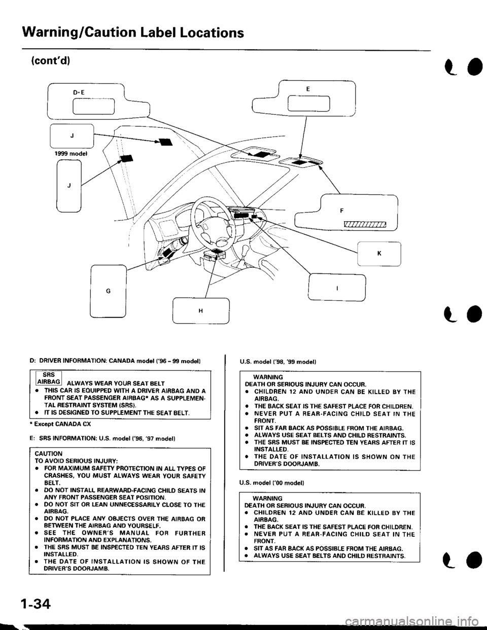
Warnin g/Gaution Label Locations
(cont'dl
to
-==-J
_)F
v7777m7na
ro
* Except CANADA CX
E: SBS INFORMATION: U.S. model ('96. '97 model)
CAUTIONTO AVOID SERIOUS INJURY:. FOR MAXIMUM SAFEW PROTECTION IN ALL TYPES OFCBASHES, YOU MUST ALWAYS WEAR YOUR SAFETYBELT.. DO NOT INSTALL REARWARD-FACING CHILD SEATS lNANY FRONT PASSENGER SEAT POSITION.. DO NOT SIT OR LEAN UNNECESSARILY CLOSE TO THEAIRBAG.. DO NOT PLACE ANY OBJECTS OVER THE AIRBAG ORBETWEEN THE AIRSAG AND YOURSELF.o SEE THE OWNER,S MANUAL FOB FURTHERINFORMATION AND EXPLANATIONS.. THE SRS MUST BE INSPECTED TEN YEASS AFTER IT ISINSTALLED,. THE DATE OF INSTALI-ATION IS SHOWN OF THEDRIVER'S DOORJAMB.
U.S. model ('00 modelI
WARNINGDEATH OR SERIOUS INJURY CAN OCCUR,. CHILDREN 12 AND UNDER CAN BE KILLED BY THEAIRBAG.. THE BACK SEAT IS THE SAFEST PLACE FOR CHILOREN.. NEVER PUT A REAR-FACING CHILD SEAT lN THEFRONT.o SIT AS FAR BACK AS POSSIBLE FROM THE AIRBAG.o ALWAYS USE SEAT BELTS AND CHILD RESTRAINTS.
D: DRIVER INFORMATION: CANADA mod6l l'96 - gtt modell
ALWAYS WEAR YOUR SEAT BELT. THIS CAR IS EOUIPPED WITH A DRIVER AIRBAG AND AFRONT SEAT PASSENGER AIRBAG' AS A SUPPLEMEN-TAL RESTRAINT SYSTEM ISRSI.. IT IS OESIGNED TO SUPPLEMENT THE SEAT BELT,
U.S. model l'98, 39 model)
WARNINGOEATH OR SERIOUS INJURY CAN OCCUR.. CHILDREN 12 AND UNOER CAN BE KILLED BY THEAIREAG.. THE BACK SEAT IS THE SAFEST PLACE FOR CHILDREN.o NEVER PUT A BEAR.FACING CHILD SEAT IN THEFRONT.. SIT AS FAR BACK AS POSSIBLE FROM THE AIRBAG.. ALWAYS USE SEAT BELTS AND CHILD RESTRAINTS.. THE SRS MUST BE INSPECTED TEN YEARS AFTER IT ISINSTALLED,. THE DATE OF INSTALLATION IS SHOWN ON THEDRIVER'S DOORJAMB.
1-34
ro
Page 37 of 2189
Llo
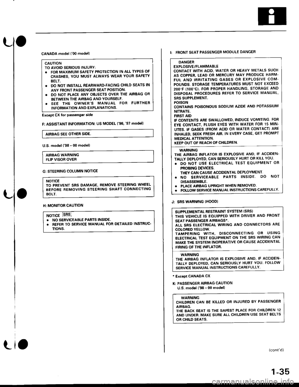
CANADA model ('00 model)
CAUTIONTO AVOID SERIOUS INJURYT. FOR MAXIMUM SAFETY PROTECTION lN ALL TYPES OF
CRASHES, YOU MUST ALWAYS WEAR YOUR SAFETY
BELT.. DO NOT INSTALL REARWARD-FACING CHILD SEATS lN
ANY FRONI PASSENGER SEAT POSITION.
. DO NOT PLACE ANY OBJECTS OVER THE AIRBAG OR
BETWEEN THE AIRBAG AND YOURSELF.. SEE THE OWNER'S MANUAL FOR FURTHER
INFORMATION AND EXPLANATIONS.
Except Cx tor passenger side
F: ASSISTANT INFoRMATION: US MODEL ('96. '97 mod€l)
AIRBAG SEE OTHER SIDE,
U.S. model l'98 - 00 modell
AIRBAG WARNINGFLIP VISOR OVER
Llo
G: STEERING COLUMN NOTICE
NOTICETO PBEVENT SRS DAMAGE, REMOVE STEERING WHEEL
BEFORE REMOVING STEERING SHAFT CONNECTING
BOLT.
ll: MONITOR CAUTION
NOTICE. NO SERVICEABIf PABTS lNSlDE.. REFER TO SERVICE MANUAL FOR DETAILED INSTRUC'
TtoNs.
DANGEREXPLOSIVE/FLAMMABLECONTACT WITH ACID, WATER OR HEAVY METALS SUCH
AS COPPER, LEAD OR MERCURY MAY PRODUCE HARM.
FUL AND IRRITATING GASES OR EXPLOSIVE COM-
POUNDS, STORAGE TEMPERATURES MUST NOT EXCEED
2OO'F I1OO"C}. FOR PROPER HANOLING, STORAGE AND
DISPOSAL PNOCEDURES REFER TO SERVICE MANUAL'
SRS SUPPLEMENT.POISONCONTAINS POISONOUS SODIUM AZIDE AND POTASSIUM
NITRATE.FIRST AIDIF CONTENTS ARE SWALLOWEO, INDUCE VOMITING. FOR
EYE CONTACT, FLUSH EYES WITH WATEB FOR 15 MIN-
UTES. IF GASES IFROM ACID OB WATER CONTACT) ABE
INHALED. SEEK FRESH AIR. IN EVERY CASE, GET PROMPT
MEDICAL ATTENTION.KEEP OUT OF REACH OF CHILDREN,
WARNINGTHE AIRBAG INFLATOR IS EXPLOSIVE AND, IF ACCIDEN-
TALLY OEPLOYED, CAN SERIOUSLY HUBT OR KILL YOU.
. DO NOT USE ELECTRICAL TEST EOUIPMENT OR
PROBING DEVICES.TH€Y CAN CAUSE ACCIDENTAL DEPLOYMENT'
. NO SERVICEABLE PABTS lNSlDE. oO NoT
DISASSEMBLE.. PLACE AIRBAG UPRIGHT WHEN REMOVED. FOLTOW SERVICE MANUAL INSTRUCTIONS CAREFULLY
I: FRONT SEAT PASSENGER MOOULE DANGER
Jr SRS WARNING IHOOD)
' Exceot CANADA CX
K: PASSENGER AIRBAG CAUTION
u.S. model l'98 - 00 model)
WARNINGCHILDREN CAN 8E KILLED OR INJUREO BY PASSENGER
AIRBAG,THE BACK SEAT IS THE SAFEST PLACE FOR CHILDREN 12
AND UNDER. MAKE SURE ALLCHILDREN USE SEAT BELTS
OR CHILD SEATS.
(cont'd)
1-35
SUPPLEMENTAL RESTRAINT SYSTEM ISRS}
THIS VEHICLE IS EOUIPPED WITH DBIVER AND FRONT
SEAT PASSENGER AIRBAGS'.ALL SRS ELECTRICAL WIRING AND CONNECTORS ABE
COLORED YELLOW.TAMPERING WITH, DISCONNECTING OR USING
ELECTRICAL TEST EOUIPMENT ON THE SRS WIRING CAN
MAKE THE SYSTEM INOPERATIVE OR CAUSE ACCIDENTAL
FIRING OF THE INFLATOR.
WARNINGTHE AIRBAG INFLATOR IS EXPLOSIVE AND, IF ACCIDEN.
TALLY DEPLOYED, CAN SERIOUSLY HURT YOU. FOLLOW
SERVICE MANUAL INSTRUCTIONS CAFEFULLY'
Page 38 of 2189
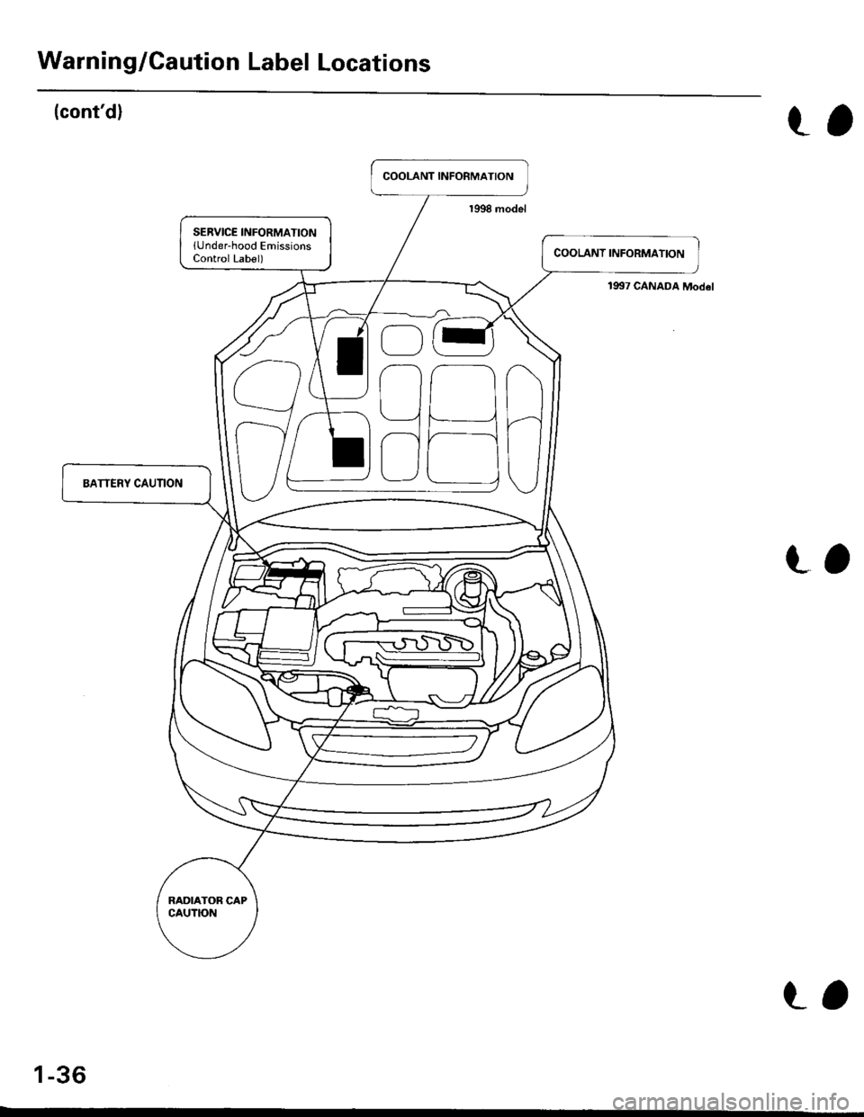
Warning/Caution Label Locations
(cont'd)
191t7 CANADA Mod6l
t,
t,
1-36
t,
Page 235 of 2189
Oil Pressure
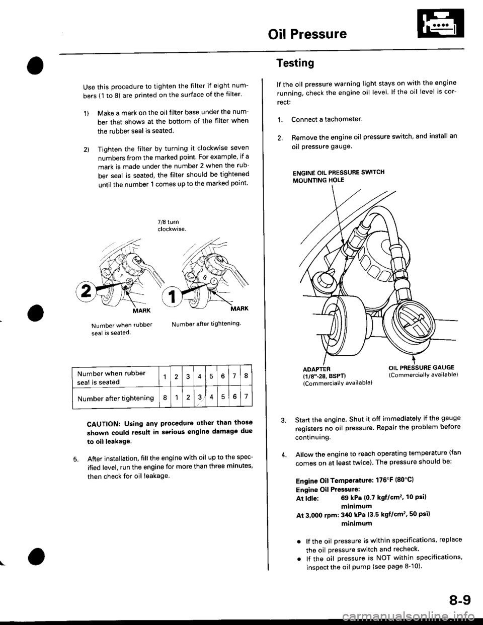
Use this procedure to tighten the filter if eight num-
bers (1 to 8) are printed on the surface of the filter.
1) Make a mark on the oil filter base under the num-
ber that shows at the bottom of the filter when
the rubber seal is seated.
2l Tighten the filter by turning it clockwise seven
numbers from the marked point. For example, if a
mark is made under the number 2 when the rub
ber seal is seated, the filter should be tightened
until the number 1 comes up to the marked point'
7/8 turn
Number when rubDer
seal is seated
Number after tightening.
CAUTION: Using any procedure other than those
shown could rosult in serious engins damage due
to oil leakage
5. After installation. fill the engine with oil up to the spec-
ified level, run the engine for more than three minutes,
then check for oil leakage
MARK
Number when rubber
seal is seated578
Number after tightening8151
Testing
lf the oil pressure warning Iight stays on with the engine
running, check the engine oil level. It the oil level is cor-
rect:
1. Connect a tachometer'
2. Remove the engine oil pressure switch, and install an
oal pressure gauge.
ENGINE OtL PRESSURE SWITCH
MOUNTING HOLE
ADAPTER(1/8\28. BSPTI
{CommerciallY availablei
Start the engine. Shut it off immediately if the gauge
registers no oil pr€ssure. Repair the problem before
continuing.
Allow the engine to reach operating temperature (tan
comes on at least tlivice). The pressure should be;
Engine Oil Temperature: 176"F (80"C1
Engine Oil Pressulo:
At ldle: 69 kPa (0.7 kgf/Gm'�. 10 Psi)
minimum
At 3.000 rpm: 3/Ut kPa (3.5 kgt/cm'�, 50 psi)
minimum
. lf the oil Dressure is within specifications, replace
the oil pressure switch and recheck.
. lf the oil pressure is NOT within specifications,
inspect the oil pump (see page 8-10).
OIL PRESSURE GAUGE(Commerciallv available)
8-9
Page 1200 of 2189
t-Operation
t
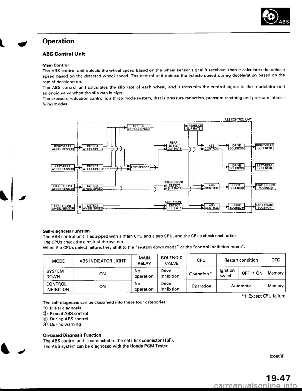
ABS Control Unit
Main Control
The ABS control unit detects the wheel speed based on the wheel sensor signal it received, then it calculates the vehicle
speed based on the detected wheel speed. The control unit detects the vehicle speed during deceleration based on the
rate of deceleration.
The ABS control unit calculates the slip rate of each wheel. and it transmits the control signal to the modulator unit
solenoid valve when the slip rate is high.
The pressure reduction control is a three-mode system, that is pressure reduction, pressure retaining and pressure intensi-
fying modes.
Self -diagnosis Funqtion
The ABS control unit is equipped with a main CPU and a sub CPU, and the CPUS check each other'
The CPUs check the circuit of the svstem.
When the CPUS detect failure, they shift to the "system down mode" or the "control inhibition mode"
The self-diagnosis can be classifield into these four categories:
O: Initial diagnosis
@: Except ABS control
@: During ABS control
@: During warning
On-board Diagnosis Funstion
The ABS control unit is connected to the data link connector {16P).
The ABS system can be diagnosed with the Honda PGM Tester.
(cont'd)
MODEABS INDICATOR LIGHTMAIN
RELAY
SOLENOID
VALVECPURestart conditionDTC
SYSTE IV
DOWNONNo
operation
Drive
inhibitionOperation*rlgnition
switchOFF + ONMemory
CONTROL
INHIBITIONONNo
operalron
Drive
inhibitionOperationAutomaticMemory
*1: Except CPU failure
/
19-47