2000 HONDA CIVIC battery replacement
[x] Cancel search: battery replacementPage 504 of 2189
I
FuelFilter
Replacement
r@. Do not smoke whilc working on fuel system. Keep
open flame away from your work arsa.
. While replacing the tuel filter, be catelul to koep a
sale distance betwoen battery torminals and any
tools.
The fuel filter should be replaced whenever the fuel
pressure drops below the specified value [260 - 310 kPa
12.7 - 3.2 ksl/cm'�,38 - 46 psi), |270 - 320 kPa (2.8 - 3 3
kgf/cm,, 40 - 47 psi))* with the fuel pressure regulator
vacuum hose disconnected and pinchedl after making
sure that the fuel pump and the fuel pressure regulator
are OK. *: 81642 engine
1. Place a shop towel under and around the fuelfilter.
2. Relieve fuel pressure (see pages 11-230,231]-
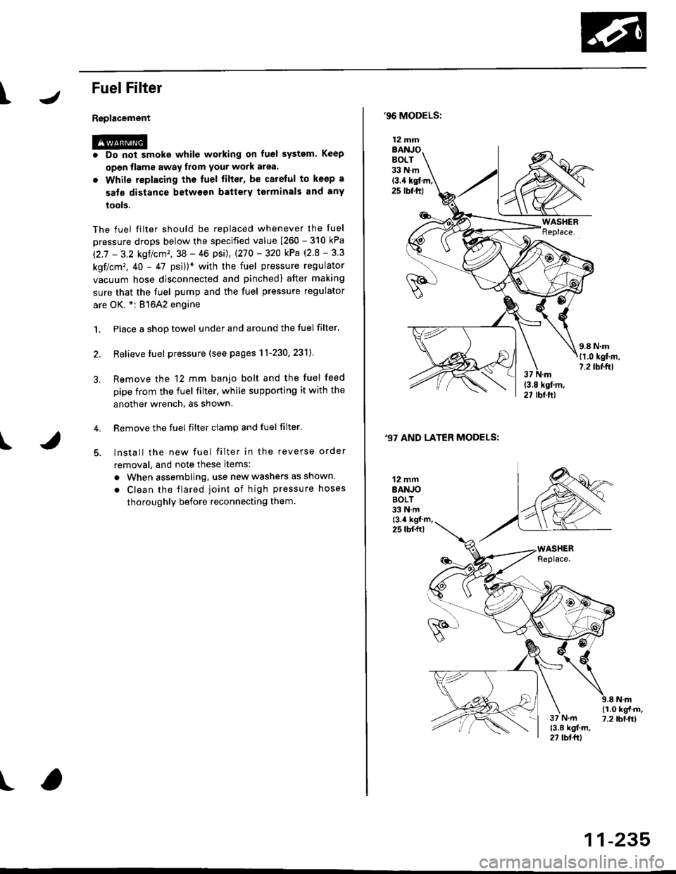
Remove the 12 mm banjo bolt and the fuel feed
pipe from the fuel filter, while supporting it with the
another wrench, as shown.
Remove the fuel filter ciamp and fuel filter'
lnstall the new fuel filter in the reverse order
removal, and note these items:
a When assembling, use new washers as shown
. Clean the flared joint of high pressure hoses
thoroughly before reconnecting them.
I
,96 MODELS:
(3.4 kgl.m,25 rbf.ftl
,97 AND LATER MODELS:
12 mmBANJOBOLT33 N.m
12 mmBANJOBOLT33 N.mt3.4 kgf m,25 lbf.fr)
\i(o-r
)
11-235
Page 505 of 2189
Fuel Supply System
Fuel Pump
Testing
!@ Do not smoke during the test, Keep open
flame away from your work atea,
lf you suspect a problem with the fuel pump, check that the
fuel pump actually runs; when it is ON (ll), you will hear
some noise if you hold your ear to the fuel fill port with the
fuel fill cap removed. The fuel pump should run for two
seconds when ignition switch is first turned ON (ll). lf the
fuel pump does not make noise, check it as follows:
L Remove the seat cushion {see section 20).
2. Remove the access panel from the floor.
3. Make sure the ignition switch is OFF, then discon-
nect the Iueltank 2P connector.
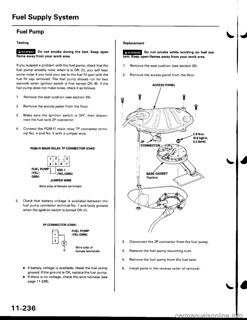
4. Connect the PGM-FI main relay 7P connector termi-
nal No. 4 and No. 5 with a jumper wire.
PGM-R MAIN RELAY 7P CONNECTOR lC4,(|l
FUEL PUMP
IYEL/GRN}
IGN 1(YEL/GRNI
tcs6s)
FUEL PUMP(YEL/GRNI
Wire side oftemale torminals
JUMPER WIRE
Wire side of temale terminals
Check that battery voltage is available between the
fuel pump connector terminal No. 1 and body ground
when the ignition switch is turned ON (ll).
CONNECTOR
=
[t
L3l .i)
T
lf battery voltage is available, check the fuel pump
ground. lf the ground is OK, replace the fuel pump.
lf there is no voltage, check the wire harness (see
page 11-238).
11-236
Replacement
@E Do not smoke while working on tuel svs-
tem. Keep open llames away from your work area.
1. Remove the seat cushion (see section 20).
2. Remove the access panel trom the floor.
3. Disconnect the 2P connector from the fuel pump.
4. Remove the fuel pump mounting nuts.
5. Remove the fuel pump from the fuel tank.
6. Install pans in the reverse order of removal.
ACCESS PANEL
i
Page 783 of 2189
Lock-up Gontrol Solenoid Valve A/B Assembly
Test
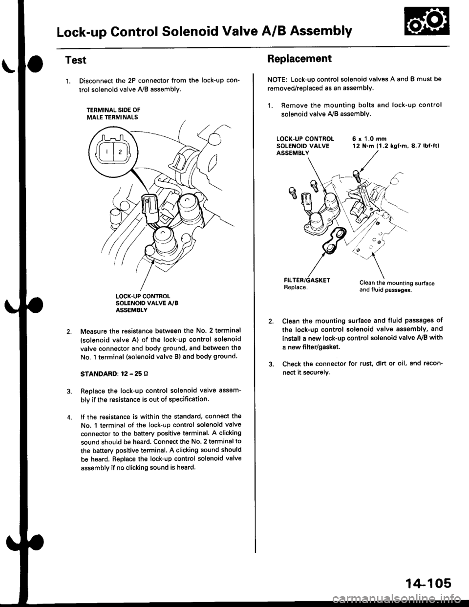
'1, Disconnect the 2P connector from the
trol solenoid valve 1y'8 assembly.
TERMINAL SIOE OF
MALE TERMINALS
tocK-up con-
LOCK.UP CONTROLSOLENOID VALVE A/BASSEMBLY
Measure the resistance between the No. 2 terminal
(solenoid valve A) of the lock-up control solenoid
valve connector and body ground, and between the
No. 1 terminal (solenoid valve Bl and body ground.
STANDARD: 12 - 25 O
Replace the lock-up control solenoid valve assem-
bly if the resistance is out of specification.
lf the resistance is within the standard, connect the
No. 1 terminal of the lock-up control solenoid valve
connector to the battery positive terminal. A clicking
sound should be heard. Connsct the No. 2 terminal to
the battery positive terminal. A clicking sound should
be heard. Replace the lock-up control solenoid valve
assembly if no clicking sound is heard.
Replacement
NOTE: Lock-up control solenoid valves A and I must bs
removed/replaced as an assembly.
1. Remove the mounting bolts and lock-up control
solenoid valve Ay'B assemblv.
6 r 1.0 mm12 N.m (1.2 kgf.m,8.7 lbl.ftl
/:'-
Clean the mounting surfaceand fluid psssages.
Clean the mounting surface and fluid passages of
th6 lock-up control solenoid valve assembly, and
instsll a new lock-up control sol€noid valve Ay'B with
a new filtsr/gask€t.
Check the connector for rust, dirt or oil, and racon-
nect it securely.
1+105
Page 784 of 2189
Shift Control Solenoid Valve A/B Assembly
Test
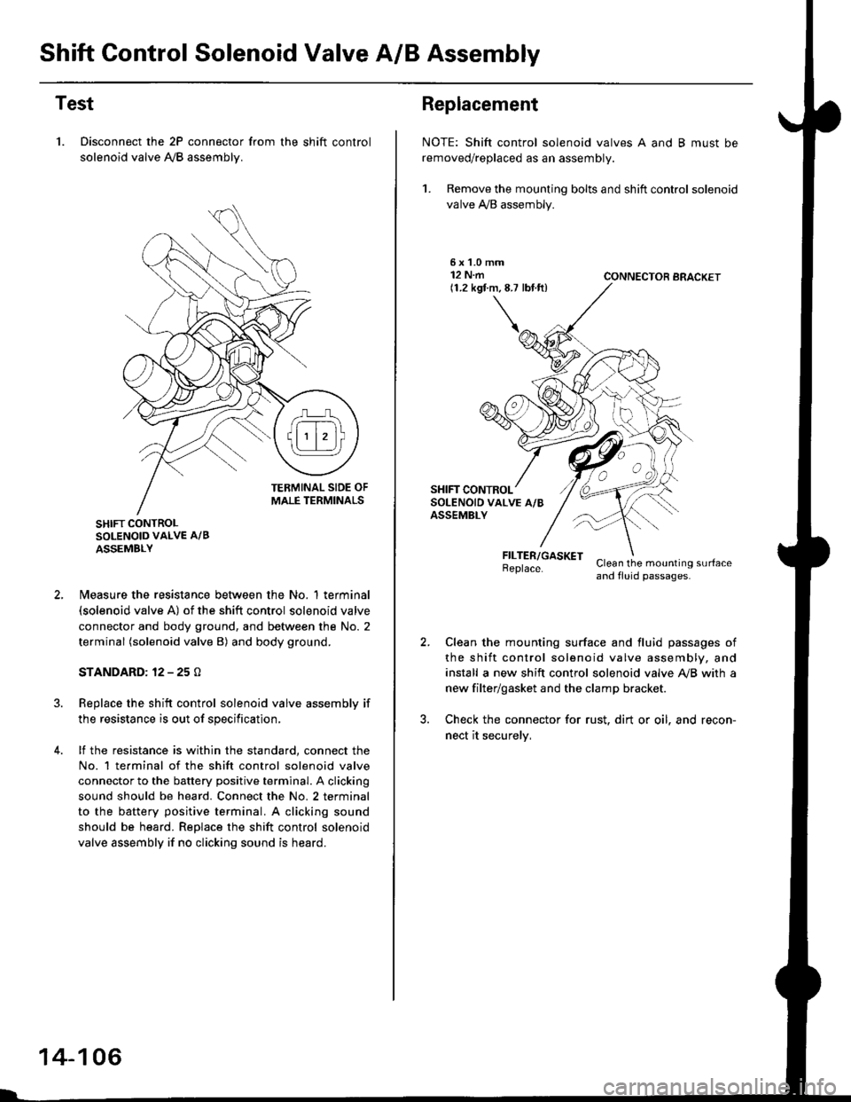
1. Disconnect the 2P connector from the shift control
solenoid valve A,/B assemblv.
SHIFT CONTROLSOLENOID VALVE A/B
ASSEMBLY
N4easure the resistance between the No. 1 terminal(solenoid valve A) of the shift control solenoid valve
connector and body ground, and between the No. 2
terminal (solenoid valve B) and body ground.
STANDARD: 12 - 25 O
Replace the shift control solenoid valve assembly if
the resistance is out of specification,
lf the resistance is within the standard, connect the
No. 1 te.minal of the shift control solenoid valve
connector to the battery positive terminal. A clicking
sound should be heard. Connect the No. 2 terminal
to the battery positive terminal. A clicking sound
should be heard. Replace the shift control solenoid
valve assembly if no clicking sound is heard.
14-106
Replacement
NOTE: Shift control solenoid valves A and B must be
removed/replaced as an assembly.
1. Remove the mounting bolts and shift control solenoid
valve A,/B assembly.
5xL0mm12 N.m(1.2 kgf.m,8.7 lbf.ft)CONNECTOR BRACKET
FILTER/GASKETBeplace.Clean the mounting surfaceand fluid passages.
Clean the mounting surface and fluid passages of
the shift control solenoid valve assembly, and
install a new shift control solenoid valve Ay'B with a
new filter/gasket and the clamp bracket.
Check the connector for rust. dirt or oil. and recon-
nect it securelv,
Page 968 of 2189
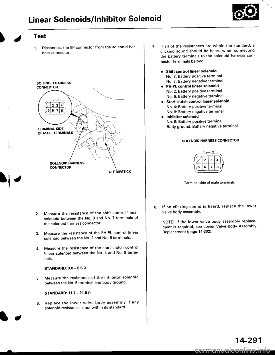
Linear Solenoids/lnhibitor Solenoid
)Test
1. Disconnect the 8P connector from the solenoid har-
ness connector.
SOLENOID HARNESSCONNECTOR
ATF OIPSTICK
Measure the resistance of the shift control linear
solenoid between the No. 3 and No. 7 terminals of
the solenoid harness connector.
Measure the resistance of the PH-PL control linear
solenoid between the No. 2 and No. 6 terminals
Measure the resistance of the start clutch control
linear solenoid between the No 4 and No. 8 termi-
nats,
STANDARD:38-6.8O
Measure the resistance of the inhibitor solenoid
between the No. 5 terminal and body ground
STANDARD:11.7 - 21.0 O
Replace the lower valve body assembly if any
solenoid resistance is not within its standard.
7. lf all ot the resistances are within the standard, a
clicking sound should be heard when connectrng
the batterv terminals to the solenoid harness con-
nector terminals below:
Shift control linear solsnoid
No.3: Batterv Positive terminal
No. 7: Battery negative terminal
PH-PL control linear solenoid
No.2: Batterv oositive terminal
No. 6: Baftery negative terminal
Start clutch control linear solenoid
No. 4: Battery Positive terminal
No.8: Battery negative terminal
lnhibitor solsnoid
No,5: Batterv Positive terminal
Body ground: Battery negative termrnal
SOLENOID HARNESS CONNECTOR
Terminal side of male terminals
lf no clicking sound is heard, replace the lower
valve body assemblY,
NOTE: lf the lower valve body assembly replace-
ment is required, see Lower Valve Body Assembly
Replacement (page 14-302).
14-291
Page 1413 of 2189
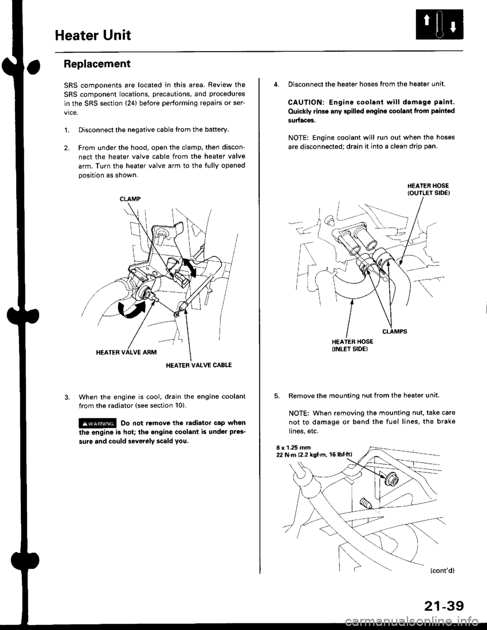
Heater Unit
Replacement
SRS components are located in this area. Review the
SRS component locations, precautions, and procedures
in the SRS section {24} before performing repairs or ser-
L Disconnect the negative cable from the battery.
2. Frcm under the hood, open the clamp, then discon-
nect the heater valve cable from the heater valve
arm. Turn the heater valve arm to the fully opened
position as shown.
When the engine is cool. drain the engine coolant
from the radiator (see section 10).
!@ Do not remove the radiator cap when
the engine is hot; the ongine coolant is under pres'
surg and could severely scald you.
CLAMP
HEATER VALVC CABLE
4. Disconnect the heater hoses from the heater unit.
CAUTION: Engine coolant will damage p8int.
Ouickly rinse any spilled engins coolant from painted
su aces,
NOTE: Engine coolant will run out when the hoses
are disconnected; drain it into a clean drip pan.
5. Remove the mounting nut from the heater unit.
NOTE: When removing the mounting nut, take care
not to damage or bend the fuel lines, the brake
lines, etc.
I x 1 .25 mm22 N.m {2.2 kgl.m, 16lblftl
21-39
Page 1420 of 2189
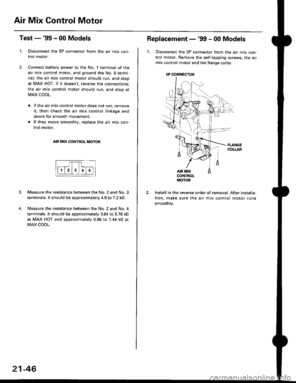
Air Mix Gontrol Motor
't.
Test -'99 - 00 Models
Disconnect the 5P connector from the air mix con-
trol motor.
Connect battery power to the No. 1 terminal of the
air mix control motor, and ground the No. 5 termi,
nal; the air mix control motor should run, and stop
at MAX HOT. lf it doesn't, reverse the connections;
the air mix control motor should run, and stop at
MAX COOL.
lf the air mix control motor does not run, remove
it, then check the air mix control linkage and
doors for smooth movement.
lf they move smoothly, replace the air mix con-
trol motor.
AIR MIX CONTROL MOTOR
Measure the resistance between the No.2 and No.3
terminals. lt should be approximately 4.8 to 7.2 kO.
Measure the resistance between the No. 2 and No. 4
terminals. lt should be approximately 3.84 to 5.76 kO
at MAX HOT and approximately 0.96 to 1.44 kO at
MAX COOL.
21-46
5P OONNECYOB
Replacement -'99 - 00 Models
1, Disconnect the 5P connector from the air mix con-
trol motor. Remove the self-tapping screws, the airmix control motor and the flange collar.
CONTROLMOTOR
Install in the reverse order of removal. After installa-
tion, make sure the air mix control motor runs
smoothly.
Page 1421 of 2189
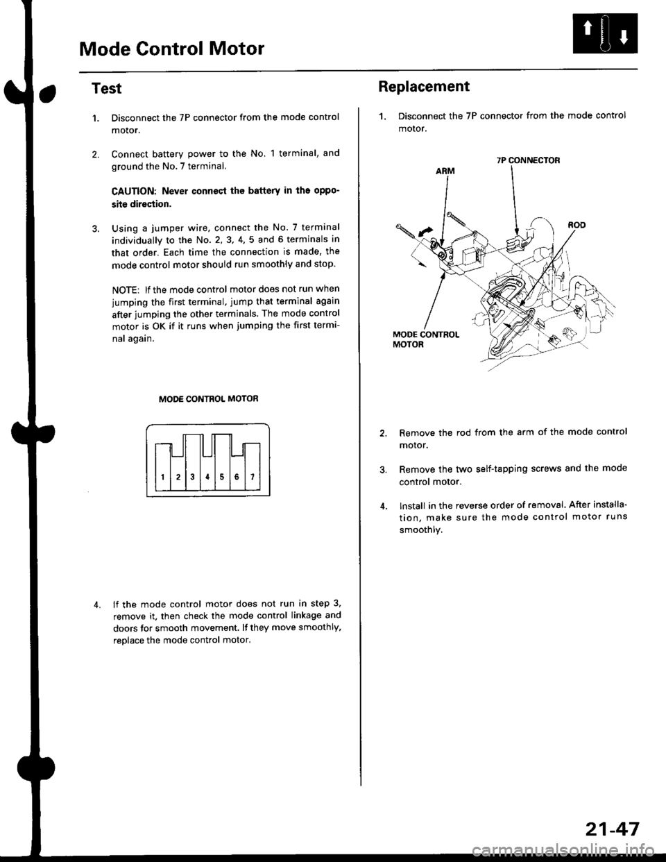
Mode Control Motor
2.
Test
1.
4.
Disconnect the 7P connector from the mode control
motor.
Connect battery power to the No, 1 terminal, and
ground the No.7 terminal,
CAUTION: Never connecl the battery in iho oppo-
site direction.
Using a jumper wire, connect the No. 7 terminal
individually to the No. 2,3, 4,5 and 6 terminals in
that order. Each time the connection is made, the
mode control motor should run smoothly and stop.
NOTE: lf the mode control motor does not run when
jumping the first terminal, jump that terminal again
after jumping the other terminals. The mode control
motor is OK if it runs when jumping the first termi-
nal again.
MODE CONTROL MOTOR
lf the mode control motor does not run in step 3,
remove it. then check the mode control linkage and
doors for smooth movement. lf they move smoothly,
reolace the mode control motor,
Replacement
1. Disconnect the 7P connector from the mode control
motor,
Remove the rod from the arm of the mode control
motor.
Remove the tyvo self-tapping screws and the mode
control motor.
lnstall in the reverse order of removal. After installa'
tion, make sure the mode control motor runs
smoothly.
7P CONNECTOR
21-47