2000 HONDA CIVIC Section 23
[x] Cancel search: Section 23Page 920 of 2189

Troubleshooting Flowchart - Vehicle Speed Sensor (VSS)
NOTE: Record all freeze data before you troubleshoot'
Po$rible Ctuse
. Disconnected vehicle speed
sensor (VSS) connectol. Short or open in VSS wire' Faulty VSS
@. Make sure lifts, iacks, and sal€tY stands are placed properly lsoe section 1)'
. Set the parking brake securelv, and block the rear wheels'
. iacr upile rront or the vehicle, and support it with safety st'nds'
TCM CONNECTORS
Wire side of female terminals
. OBD ll Scan Tool indicates Code
P1791.. Setf-diagno3is E indicato. light
blinks tour times.
Refer to seclion 23 for vehicle
soeed sensor IVSSI test
Check the VSS Voltage:
1. Raise the vehicle2. Shift the transmission to lEposrtlon.3. Disconnect the A (26P) and B(22P) connectors from the
TCM.4. Turn the ignition switch ON {ll).
5. Rotate the front wheel and
check for the voltage between
the 85 and 413 or A26 termi-
nals. Block the other wheel so
at does not turn
Check for oP€n in the wire
between the 85 terminal and the
vehicle speed sensor {VSS}. lf
wire is OK, check the vSS (see
soction 23).
Does0Vandapprox 5 V or more
appear alternatelY?
Check for loos€ TCM connedors
lI nec€ssary, substitute a known'
good TCM and recheck.
14-243
Page 926 of 2189

Troubleshooting Flowchart - Manifold
NOTE: Record all freeze data before you troubleshoot
Absolute Pressure {MAPI Sensor
TCM CONNECTORS
Wire side of female terminals
PG.iblo Cau3€
. Dkconnoctod manilold .bsoluto
ore33urc IMAP) sensor connoc'
lor. Short or opcn in MAP s.nsor
MAP sen3or
. OBD ll Scan Tool indicates Code
P1793,. self-diagno3b E indicato. light
indicat€s Code 12.
Chock tor Another Cod€ or MIL
Blinking:1. Turn the ignition switch ON (ll).
2. Check whether the OBD ll scan
tool indicates another code or
the Mal{unction Indicator LamP(MlL) blinks (sse section 11).
Does the OBD llscan tool indicate
another code or isthe lVlL blink-
in9?
Measure VREF voltage:
1. Turn the ignition switch OFF.
2. Disconnect the A (26P) and B
(22P) connectors trom the
TCM.3. Turn the ignition switch ON (ll).
4, Measure the voltage between
the B2O and A13 or A26 termr
nals.
R€pair opon or 3hort in the wire
botwoan the 820 t€.minal and
the EcM.lsthere aPprox.5 V?
Msasure MAP IPB) volt.ge:
Measure the voltage betlveen the
82 and A13 or 426 terminals.
Repair opon ot shorl in the wiro
betwesn the 82 torminal end th€
MAP sensol.ls there approx. 3 V?
Check for loo3e TCM conn€stors.
lf nec*sarY, sub3titute a known'
good TCM and rechock.
WHT/RED
14-249
Page 940 of 2189

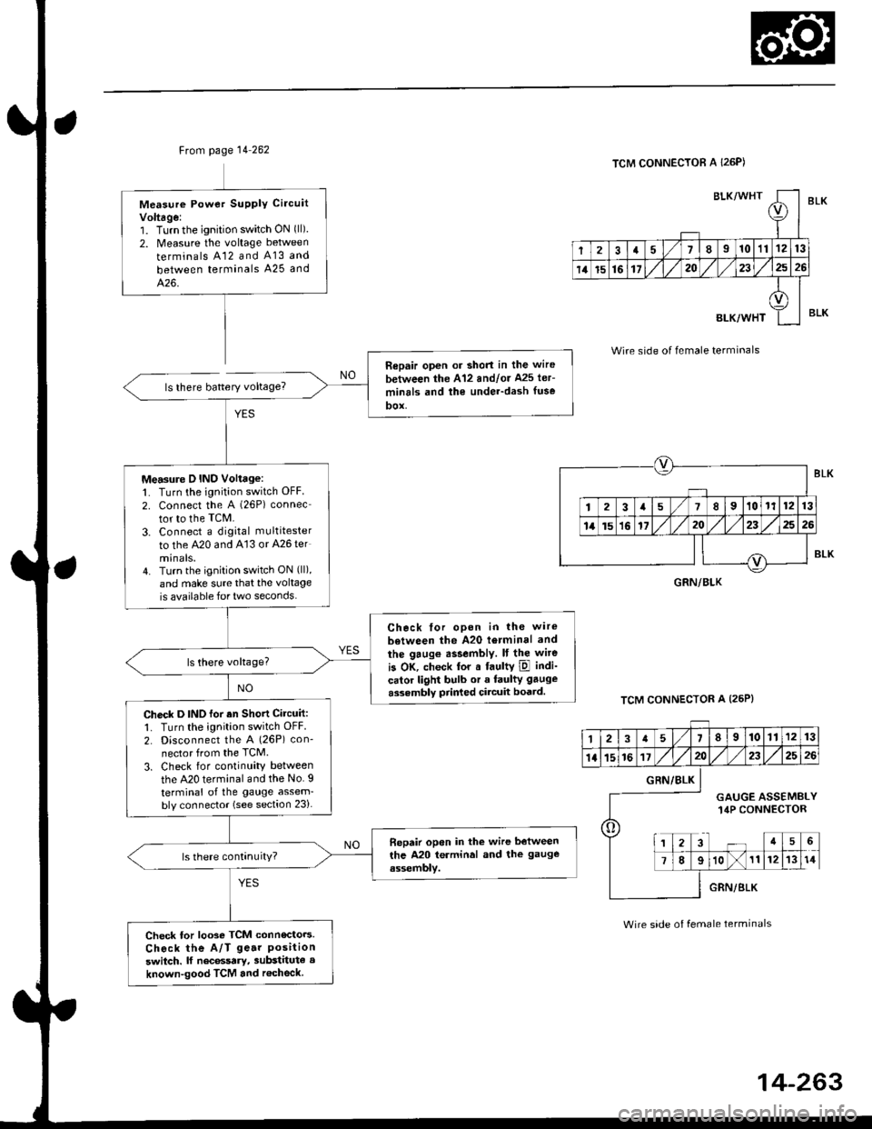
Ftom page 14 262
ls there battery voltage?
Measure Powet SUPPIY Ci.cuit
Voltage:1. Turnthe ignition switch ON (ll)
2. Measure the voltage between
terminals A12 and A13 and
between terminals A25 and
426.
Repair open or short in the wire
between the A'12 andlor Ms ler-
minrls and the under-dash fuse
DOX,
Measure D IND Voltage:1. Turn the ignition switch OFF
2. connect the A (26P) connec
tor to the TcM.
3. Connect a digkal multitester
to the A20 and A'13 or A26 ter
minals.4. Turn the ignition switch ON (ll),
and make sure that the voltage
is available for two seconds.
Check tor opon in the wire
between the A20 l6rminal and
the gaug€ assembly. It the wite
is OK, check tor a faultY ipl indi-
calor light bulb or a faulty gauge
assembly prir ed circuit boatd.
Check D INO for an Shott Circuit:1. Turn the ignition switch OFF
2. Disconnect the A (26P) con-
nector from the TCM.
3. Check for continuity between
the A20 terminal and the No. I
terminal of the gauge assem-bly connector (see section 23).
Bepair open in the wire between
the A20 terminal and the gauge
assembly.
Check tor looso TCM connecto.s.
Check the A/T ge.r Positionswitch. lf nec6ssary, substitute a
known-good TCM and r€check
BLK/WHTI
r
2a710111213
14t5161720232526
BLK/WHT
A
II
TCM CONNECTOR A I26P)
Wire side of female terminals
TCM CONNECTOR A (25P}
BLK
BLK
GRN/BLK
12a58910111213
1l15161720232526
o
GRN/BLK
GAUGE ASSEMBLY14P CONNECTOR
a5
78910111214
GRN/BLK
Wire side of female terminals
Page 945 of 2189

Electrical Troubleshooting {'99 - 00 Models)
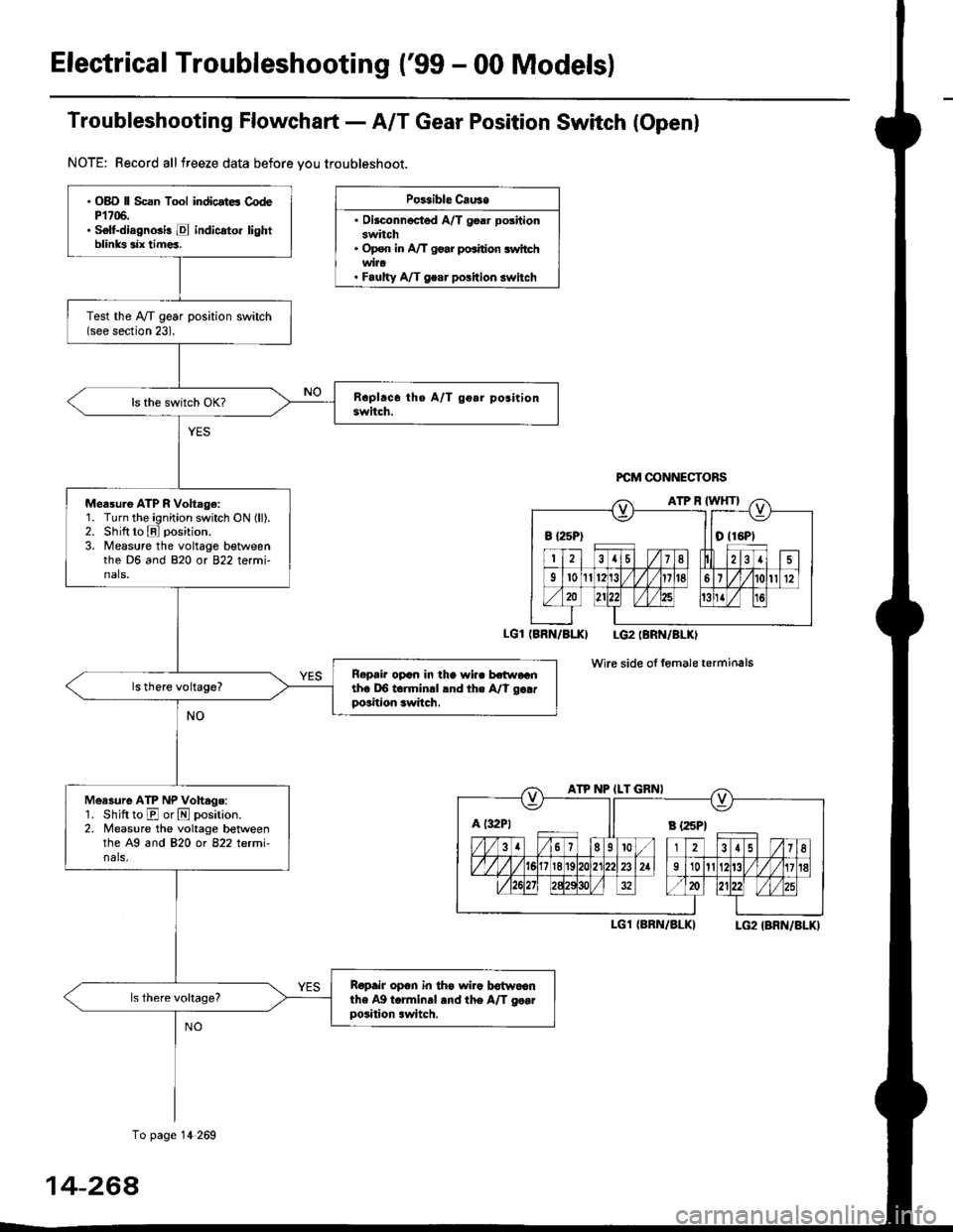
Troubfeshooting Flowchaft- AIT Gear Position Switch (Openl
NOTE: Record allfreeze data before vou troubleshoot.
Po$ible Cau3e
. Oilconnected A/T goar positionswitch. Op€n in A/T go.r po.ition switchwi?o. Faulty A/T gear polition switch
PCM @NNECTORS
(BRN/BI.XI LG2IBRN/BLKI
wire side of fomale terminals
I-G1 (BRN/BLKILG2 {BRN/BLK)
B {25P) I tO (16P1
ATP NP ILT GRNI
A t:r2Pt Il s tzspt
. OBD ll Scan Tool indicstE CodeP1706.. Selt-diagnGi! E indicato. lightblinks six tim€a.
Test the IVT gear position switch(see section 23).
Measu.e ATP R Voltage:1. Turn the ignition switch ON (ll).2. Shift to E position.
3. Measure the voltage betweenthe D6 and 820 or 822 termi-nals,
Ropair opcn in the wi.. hr.raGnth6 DO torminrl lnd the A/t g..rposition awitch.
Measure ATP NP Vohage:'1. Shift to E or N position.2. Measure the voltage betweenthe A9 and 820 ot 822 letmi-nals,
Ropair op6n in th€ wiro b€{woanthe Ag t.rminal and the A/T go..position .witch.
To page 14 269
14-264
Page 967 of 2189

ElectricalTroubleshooting ('gg - 00 Models)
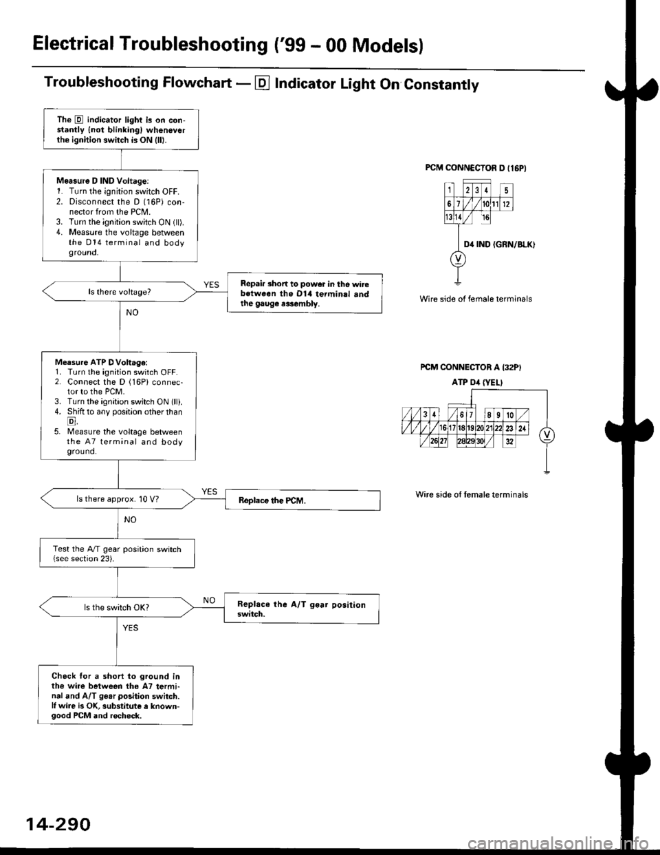
Troubleshooting Flowchart - E Indicator Light On Constantly
FCM CONNCCTOR D tl6PI
23I5
61t012
tsll / rc
II D4 rND
o
(GRN/BLK)
Wire side of female terminals
rcM CONNECTOR A I32PI
ATP Dil {YELI
Wire side of lemale terminals
The E indicator light is on con-stantly {not blinkingl wheneverthe ignition switch is ON lll|.
Mersure D IND Voltage:1. Turn the ignition switch OFF.2. Disconnect the D (16P) con-nector from the PCM.3. Turn the ignition switch ON (ll).4. Measure the voltage betweenthe 014 terminal and bodyground,
Repair short to power in tho wirebstween the Dl4 termin.l sndthe gaug€ r3sembly.
Measure ATP DVoltage:1. Turn the ignition switch OFF.2. Connect the D (16Pi connec-tor to the PCM.3. Turn the ignition switch ON lll).4. Shift to any position other thanE,5. lMeasure the voltage betweenthe 47 terminal and bodyground.
ls there approx. 10 V?
Test the A/T gear position switch{see section 23).
Check for a shorl lo ground inthe wire between tho A7 termi-nal and A/T ge.r polition switch.l, wire is OK, substitute a known-good PCM and recheck.
14-290
Page 977 of 2189

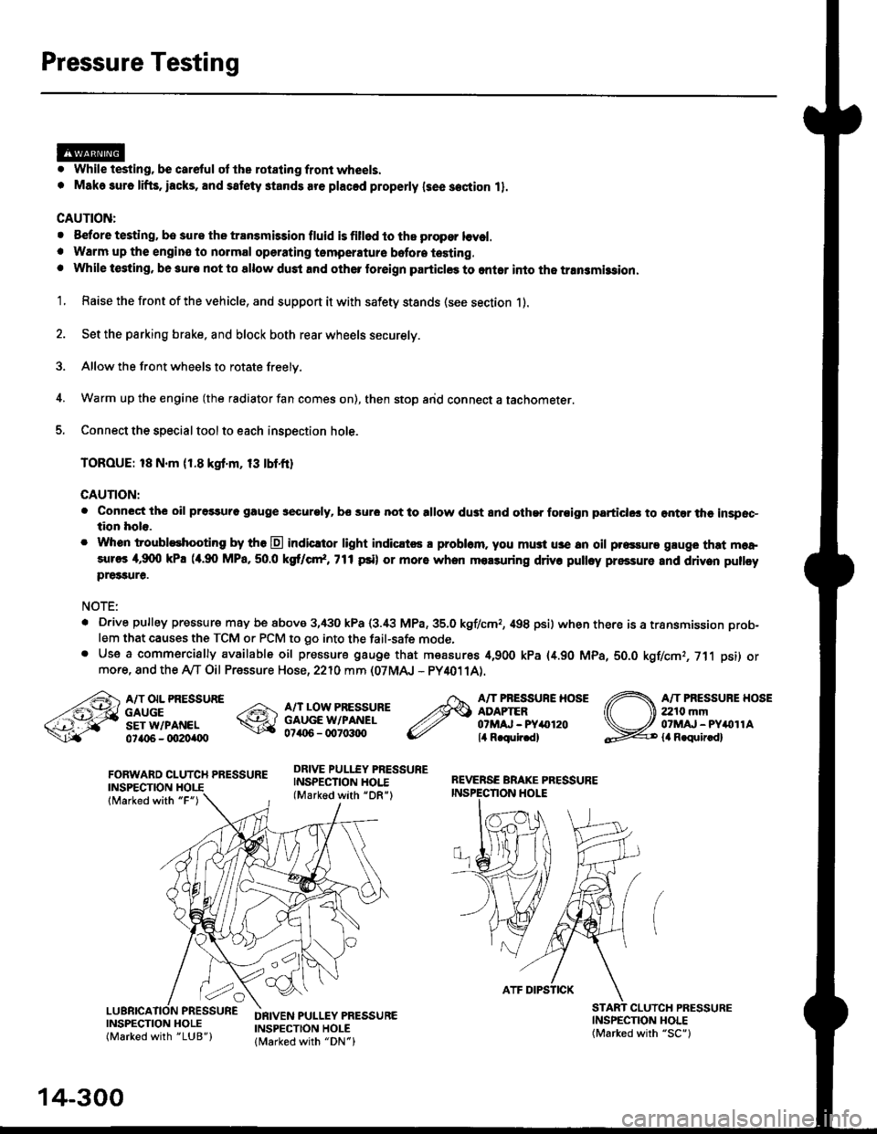
Pressure Testing
. While testing, be careful of the rot8ling front wheels.
. M8k6 suro lifts, iacks, and satety stands are placed properly lsee section 11.
CAUTION:
. Before testing, be sur. the transmb3ion fluid is fillod to the propor lcvel.. Warm up the engin€ to nolmal operating tsmperature bofore testing. While t€sting, be 3ure not to allow dust and other loreign particles to onler into the transmi$ion.
1. Raise the front of the vehicle, and support it with safety stands (see section 1).
2. Set the parking brake. and block both rear wheels securely.
3. Allow the front wheels to rotate freely.
4. Warm up the engine (the radiator fan comes on), then stop arid connect a tachometer.
5. Connect the special tool to each inspection hole.
TOROUE: 18 N.m (1.8 kgt'm, 13 tbtfr)
GAUTION:
. Connect the oil pressuro gauge !!€curoly, bs sur6 not to allow dust and other foroign particlG3 to ontar the inspsc-tion hole.
. Whon troubleshooting by tho E indicltor light indic.t6 a problam. you mu3t u3e an oil p.essure gluge that moa,sures 4,9(X) kPa (a.90 MPa,50.0 kS cr*,771psi) or more when molsuring driv. pulley pressure and driven pullcypre33ure.
NOTE:
. D.ive pulley pressure may be above 3,430 kPa (3.i8 MPa,35.0 kgf/cmr, 498 psi) wh€n there is a transmission prob-
lem that causes the TCM or PCM to go into the fail-safe mode,. Use a commercially available oil pressure gauge that measures 4,900 kPa {4.90 MPa, 5O.O kgf/cmr, 711 psi) ormore, and the Ay'T Oil Pressure Hose, 2210 mm (07MAJ - PY4011A).
FORWARD CLUTCH PRESSUREINSPECTION
lMarked with "F")
REVERSE BRAKE PRESSUREINSPECTION I.IOLE
A/T OIL PRESSUREGAUGESET W/PANEL0ta{r6 - oO2Oi|(Xt
A/T LOW PRESSUREGAUGE W/PANEL0706 - qt7o:t{ro
DRIVE PULLEY PRESSUREINSPECTION HOI.E(Marked with "DR")
A/T PRESSURE HOSEADAPTER07MAJ - PYar'120lil R.qulr.d)
A/T PRESSUBE HOSE2210 mm07MAJ - PYitollAla R.quir.d)
(
INSPECNON HOLE(Marked with "SC")
CLUICH PRESSURE
INSPECTION HOLE(Marked with "LUB")
DRIVEN PULLEY PRESSUREINSPECTION HOLElMarked with "DN")
14-300
ATF DIPSTICK
Page 979 of 2189

Lower Valve Body Assembly
Replacement
@ Make sure lifts, iacks, and saf€ty stands
are placsd prop€rly {sea section 1).
CAUTION: While removing and installing th6 lower
valve body asssmbly, b€ sule not to allow dust and
other for€ign particles to entsr inio the transmksion.
1. Raise the front of the vehicle, and support it with
safetv stands (see section 1).
2. Set the parking brake, and block both rear wheels
securetv.
4.
6.
Remove the drain plug, and drain the CVT fluid.
Reinstall the drain plug with a new sealing washer(see page 1+299).
CAUTION: Keop all of other toreign parliclos out of
the transmission.
Disconnect the 8P connector from the solenoid har-
ness connector.
Remove the ATF cooler hoses at the ATF cooler
lines. Turn the ends of the ATF cooler hoses up to
prevent ATF from flowing out, then plug the ATF
cooler noses.
CAUTION: Keep all of other foroign particlo3 out of
tho transmission.
Remove the right front mounvbracket.
10 x 1.25 mmila N.m (,1.5 kgf.m, 33 lbtft)
RIGHT FRONTMOUNT/BRACKET
ATF COOLER LINE
10 x 1.25 mmsil N.m 15.5 kgf.m,40 rbr.ft)
ATF COOLER HOSE
14-302
14.
7. Remove the ATF cooler outlet line.
8. Remove the ATF cooler line bracket bolt.
9. Remove the ATF pan (fourteen bolts).
10. Remove the ATF strainer (two bolts).
1 l. Remove the one bolt securing the solenoid harness
connector,
12. Remove the
bolts).
lower valve body assembly (eight
LINE BOLT28 N.m (2.9 kgtm,21 lbtft)SEALINGReplace.
ATF COOI.-EROUTLET
OOWEL PIN
O.RINGFeplace.
SOLENOIO HARNESSCONNECTOR
5x1.0mm12 N.m 11.2 kgt.m,8.7 tbt.ftlO.RINGReplace.ATFSTNAINER
6x1.0mm12 N.m 11.2 kgt m,E.7 tbt'ft)
OOWEL NN
BODY ASSEMBLY
6x1.0mm12 N.m 11.2 kgf.m,8.7 rbf.ft)
ATF PAN GASKETReplace.
VALVE
ATF COOLER INLETUNE BRACKET BOLT8 x 1,25 mm26 N.m {2.7 kgf.m,20 tbf.frl
13.
ATF PANx 1.0 mm12 N.m 11.2 kgf.m, E.7 lbf.ftl
Install the new lower valve bodv in the reverse
ordgr of the removal orocedure.
CAUTION: Koep all ot other fo.oign particles out of
ths transmission.
NOTE:
. Replace the following parts:
- O-rings on the solenoid harness connector
and the ATF strainer- ATF pan gasket- Sealing washers
. lf the ATF cooler inlet line bracket is bent or
warped, put it back to the original position.
Perform the start clutch calibration orocedure on
page 14-293.
Page 980 of 2189

ATF Filter
l.Removal/lnstallation
!@ Make sure lifts, lEcks, snd safoty stands
ara pl8ced properly {sae section 1).
CAUTION: While removing and installing the ATF tilier,
be sure not to allow dust or other for6ign particle3 to
enter thg transmission.
1. Raise the front of the vehicle, and support it with
safety stands (see section 1).
2. Set the parking brake, and block both rear wheels
securely.
3. Remove the drain plug, and drain the CVT fluid.
Reinstall the drain plug with a new sealing washer
{see page 14-299).
fl,
5.
CAUTION: Keep all toreign particles out ot the
transmission.
Remove the ATF cooler hoses at the ATF cooler
lines. Turn the ends of the ATF cooler hoses up to
prevent ATF from flowing out, then plug the ATF
cooler noses.
CAUTION: Keep all foreign particles out of the
transmission.
Remove the right front mounvbracket.
10 x 1.25 mm4{ N.m {i1.5 kgf.m,33 lbf ft)
ATF COOLER LINE
10 x 1.25 mm54 N.m {5.5 kgt'm,
40 rbl.ft)
ATF COOLER HOSE(|'t
14-303
6. Remove the ATF cooler outlet line.
7. Remove the ATF cooler line bracket bolt.
8. Remove the ATF pan (fourteen bolts)
9. Remove the ATF cooler inlet line from the ATF pan
(three bolts).
10. Remove the ATF filter, and clean it.
11. Check that the ATF filter is in good condition.
12. Replace the ATF filter if it is clogged.
LINE BOLT28 N.m {2.9 kgf.m,21 lbt.ft)
ATF COO1TR OUTIET
6x1.0mm
ATF COOLER INI-ETLINE ERACKET BOLT8 x 1.25 mm26 N.m (2.7 kgt.m,20 rbtftt
O.RINGReplace.
ATF
ATF FILTER
ATF PAN
6x1.0mm12 N.m (1.2 kgt'm,8.7 lbl'ft)
lnstall the ATF filter in the reverse order of the
removal procedure.
GAUTION: Keep all foreign particles out ot the
transmission,
NOTE:
Replace the O-rings, the ATF pan gasket and
sealing washers.
lf the ATF cooler inlet line bracket is bent or
warped. put it back to the original position
GASKETReplace.
'13.
12 N m (1.2 kgf m,