Page 983 of 2189

Transmission
Removal (cont'd)
10. Remove the cotte. pins and castle nuts, then separatethe ball joints from the lower arm (see section 1g).
SELF-LOCKING -=V,
NUT \Replace. oitupea rOax
Remove the right damper fork bolt, then separateright damper fork and damper.
Pry the right and left driveshafts out of the differen-tial.
Pull on the inboard joint to remove the right and leftdriveshafts (see section 16).
Tie plastic bags over the driveshaft ends.
NOTE: Coat all precision finished surfaces with cleanengine oil.
Remove the exhaust pipe A.
/\<,\CASTLE I{UT COTTERReplac6.
't 1.
't2.
tJ.
14.
q.
SELF.LOCKINGNUTReplace.
SELF.LOCKING NUTReplace.
14-306
EXHAUST PIPE A
19.
'16, Remove the right front mounvbracket,
ATF COOLER HOSE
17. Remove the ATF cooler hoses at the ATF coolerlines. Turn the ends of the ATF cooler hoses uo toprevent CVT fluid from flowing out, then plug theATF cooler hoses and lines,
NOTE: Check for any sign of leakage at the hosejoints.
18. Remove the engine stiffeners and the flywheel cover.
Remove the eight drive plate bolts one at time whilerotating the crankshaft pullev.
ENGINE STIFFENER
Page 1025 of 2189

l.
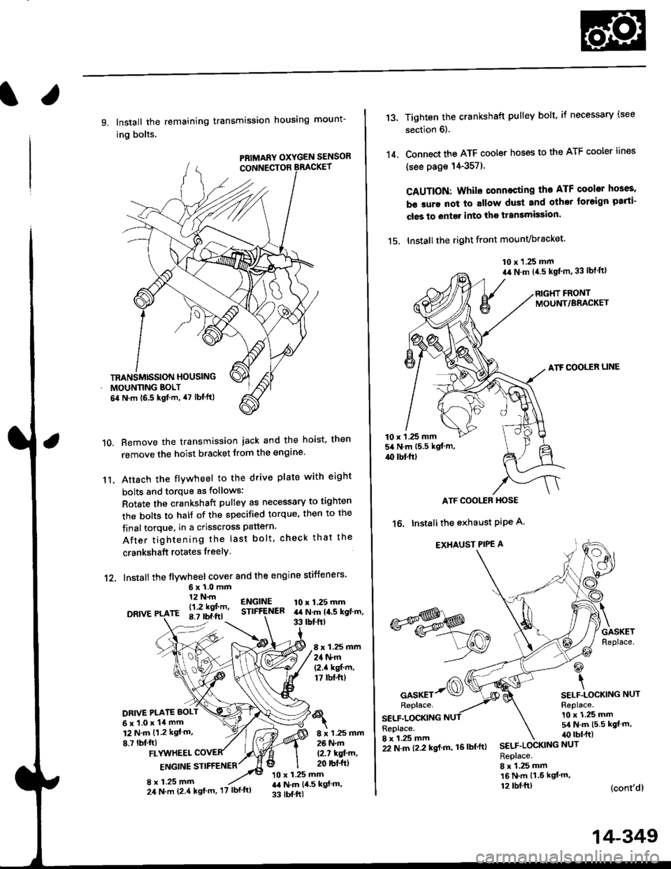
9. Install the remaining transmission housing mount-
ing bolts.
PRIMARY OXYGEN SENSOR
Remove the transmission jack and the hoist. then
remove the hoist bracket from the engine'
Attach the flvwheel to the drive plate with eight
bolts and torque as follows:
Rotate the crankshaft pulley as necessary to tighten
rhe bolts to half of the specified torque, then to the
final torque, in a crisscross pattern.
After tightening the last bolt. check that the
crankshaft rotates freelY.
10.
11.
12. Install the flywheel cover and the engine stiffeners
DRIVE
6xl.0mm12 N.m
- l12 kgf'm'rE 8.7 tbf.ftl
ENGINESTIFfENEB10 x 1.25 mmart N.m la.s kgt.m,33 tbtftt
8 x 1.25 mm24 N.m(2.1 kgf'm,17 tbt.ftt
DRIVE PI.ATE BOLT
6x1.0x14mm12 N.m {1.2 kgt m.
8.7 lbf,ftl8 x 1.25 mm26 N.m
12.7 kqfin,20 rbt'ftlFLYUTHEEL
ENGINE STIFFENER
8 x 1.25 mm10 x 1.25 mmr,a N.m {4,5 kgf m,
33 tbf.ftl
TRANSMISSION HOUSING
MOUNNNG BOLT
6il N.m {6.5 kgf.m, 47 lbf'ftl
24 N.m (2.4 kgt'm, '17 lbf'ftl
22 N.m t2.2 kgl m, 16lbf'ftl
14-349
13.
14.
Tighten the crankshaft pulley bolt, if necessary (see
section 6).
Connect the ATF cooler hoses to the ATF cooler lines
(see page 14-357).
CAUTION: Whilo connecting the ATF cooltr hGes,
b€ sure not lo allow dust and other loreign parti-
cles to entg. into the transmission.
15. Installthe right front mounvbracket'
10 x 1.25 mm
a,r N.m {4.5 kgf'm,33 lbt ftl
RIGHT FRONTMOUNT/BRACKET
ATF COOLER LINE
10 x 1 .25 mm54 N.m {5.5 kgt'm,
4{) tbl.ftt
ATF COOI,TR HOSE
16. Installthe exhaust PiPe A.
EXHAUST PIPE A
GASKETReplace.
@
\SELF.LOCKING NUTReplace.10 x 1.25 mm5/a N.m {5.5 kgt m,irc lbf.ft)
(cont'dl
*s$o
oor*rr-@Replace.
SELF.LOCKINGReplace.8 x 1.25 mmSELF.LOCKING NUT
Replace.8 x 1.25 mm16 N.m {1.6 kgl'm,12 tbl.ftt
Page 1026 of 2189

Transmission
17.
Installation (cont'd)
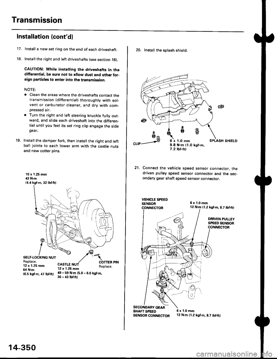
Install I new set ring on the end of each driveshaft.
Install the right and left driveshafts (see section 16).
CAUTION: While instatling the drive3hafts in thedifferential, be sure not to allow dust and olher for-aign particles to enter into tho transmission.
NOTE:
. Clean the areas where the driveshafts contact thetransmission {differential} thoroughly with sol-vent or carburetor cleaner, and drv with com-
Dressed air.
. Turn the right and left steering knuckle fully out-wa.d, and slide each driveshaft into the differen-tial until you feel its set ring clip engage the sidegear.
Install the damper fork, then install the right and leftball joints to each lower arm with the castle outsand new cotter pins.
19.
10 x 1.25 mm43 N.m{4.4 kgf.m, 32 lbf.ftl
SELF-LOCKING NUTReplace.12 x 1.25 mm6l N.m
CASTI.I'12 x 1.25 mm
{6.s ksr.m. 47 tbr.ftr l! _ ll ffiteo
- s.o tet'.,
14-350
20. Install the splash shietd.
aa
I6I6*
"a,a s
21.
SECONOARY GEARSHAFT SPEEDSENSOB CONNECTOR
6 x 1.0 mm9.8 t{.m 11.0 kgt.m,7.2 tbf.trl
Connect the vehicle speed senso. connector. thedriven pulley speed sensor connector and the sec-ondary gear shaft speed sensor connector,
6x1,0mm12 N.m {1.2 kg{.m, 8.7 tbf,ft)
DRIVEN PULLEYSPEED SENSORCONNECTOR
E.
6 x 1.0 m.rl'12 N.m {1.2 kg{.m,8.7 tbf.fo
Page 1027 of 2189

22. Install the shift cable end on the control lever, and
install the shift cable on the shift cable bracket'
CAUTION: Take care not to bend the shift cable'
23. lnstall the clip in the direction shown.
LOCKNUT
SHIFI CABLE 29 N m {3.0 kg{ m, 22lblftl
SHIFT CABLEERACKET
WASHERIPLASTIC)
CONTROL LEVER
24, Connect the solenoid harness connector. the drive
pulley speed sensor connector. and the ground
cable terminals.
6x1.0mm12 N.m {1.2 kgf.m.8,7 rbtft)
GROUND CABLETERMINAL 6x1.0mm
GROUNDTERMINAL
12 N.m {1.2 kgf'm,8.7lbtfrl
DRIVE PULLEYSPEED SENSORCONNECTOR
SOLENOID HARNESS
CONNECTOR
25. Connect the starter motor cable on the starter motor.
and install the cable holder.
NOTE: When installing the staner motor cable. make
sure that the crimped side of the ring terminal is
facing out (see section 23).
STARTEB
BMOUNTING NUT
9 N.m (0.9 kgf m,7 lbf ft)
26. Install all removed connectors and clamps'
27. Install the distributor.
28. Install the intake air duct and air cleaner housing
29.
assemDly.
Refill the transmission with the recommended
Genuine Honda CVT Fluid (see page 14-2991
CAUTION: While filling the CvT Fluid, bs surs not io
allow dust and other fotoign particles to entor into
the transmission.
Connect the battery positive (+) terminal first, then
the negative (-l terminal to the battery'
Check the ignition timing (see section 23).
Start the engine. Set the parking brake, and shift the
transmission through all gears three times Check
shift cable adjustment (see page 14-355).
Check the front wheel alignment (see section 18)
Let the engine reach operating temperature (the
radiator fan comes on) with the transmission in lXl
or E position, then turn it off and check fluid level'
Perform the start clutch calibration procedure on
page 14-293.
Road test as described on pages 14-296 and 14-297
30.
31.
34.
36.
STARTER MOTOR
14-351
Page 1030 of 2189
Shift Cable
RemovaUlnstallation
@ Make sure lifts, iacks and safety stands are
placed properly (see seqtion 11,
1. Remove the front console (see section 20).
2. Shift to E position, then remove the lock pin from
the adiuster.
ADJUSTER
14-354
Remove the air cleaner housing assembly.
Remove the clip from the control lever, and loosen
the locknut.
CLIP SHTFT CABLE LOCKNUT29 N.m 13.0 kgf m,22 lbf.ft)
SHIFT CABI-EBRACKET
7.
8.
CONTROL LEVER
Remove the shift cable from the control lever, the
shift cable bracket, and the clamp.
Remove the shift cable bracket bolts and nuts, then
remove the shift cable. Take care not to bend the
shift cable when removing/installing it.
SHIFT CABLE BRACKET
lnstall the shift cable in the reverse order of removal.
Check the cable adjustment (see page 14-355).
\.
*o"ra" \
{1.2 kgI m, 8.7 lblft)
Page 1031 of 2189

t
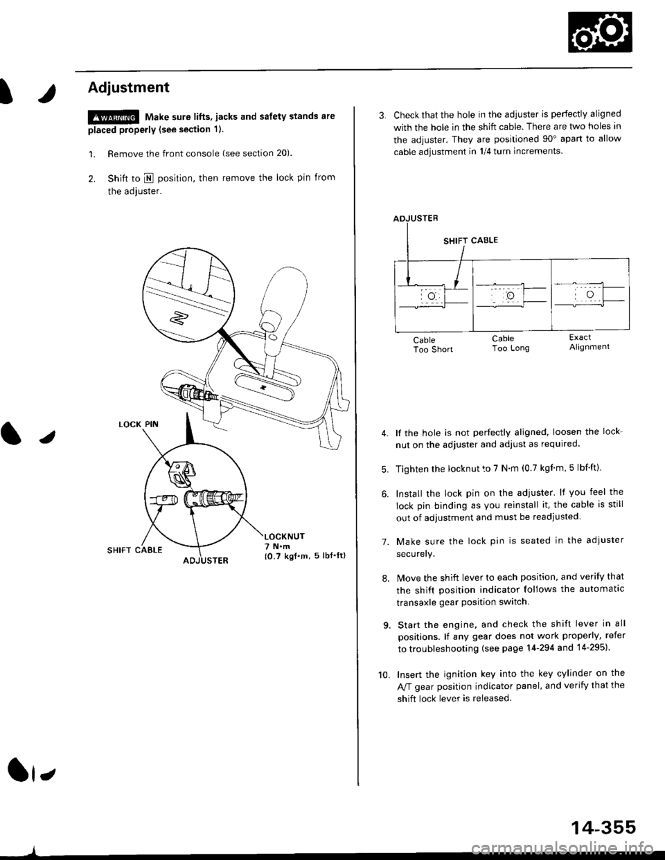
Adjustment
!@ Make sure lifts, jacks and safety stands are
placed properly (see section 1).
l. Remove the front console (see section 20).
2. Shift to I posirion, then remove the lock pin from
the adjuster.
SHIFT CAELE
l,
,l
{0.7 kgf.m, 5lbf'ltl
3. Check that the hole in the adiuster is perfectly aligned
with the hole in the shift cable. There are two holes in
the adjuster. They are positioned 90" apart to allow
cable adjustment in 1/4 turn increments.
lf the hole is not perfectly aligned, loosen the lock-
nut on the adjuster and adjust as required.
Tighten rhe locknut to 7 N.m (0.7 kgim,5 lbf'ft).
Install the lock pin on the adjuster' lf you feel the
lock pin binding as you reinstall it. the cable is still
out of adjustment and must be readjusted
Make sure the lock pin is seated in the adiuster
securery.
lMove the shift lever to each position, and verify that
the shift position indicator follows the automatlc
transaxle gear position switch.
Start the engine, and check the shift lever in all
positions. lf any gear does not work properly, refer
to troubleshooting (see page 14-294 and 14-295).
Insert the ignition key into the key cylinder on the
Aff gear position indicator panel, and verify that the
shift lock lever is released.
7.
10.
14-355
Page 1033 of 2189
Shift Indicator PanelATF Gooler/Hoses
Adjustment
1.Check that the index mark on the indicator aligns
with the E mark on the shift indicator panel when
the transmission is in NEUTRAL.
lf not aligned, remove the front console {see section
20).
Remove the shift indicator panel mounting
and adjust by moving the panel.
NOTE: Whenever the shift indicator panel is removed,
reinstallthe Danel as described above.
It,
14-357
lnstallation
1. Installthe ATF cooler, ATF cooler line assembly and
the ATF cooler hoses.
6x1.0mm11 N.m ('l 1 kgf.m,8.0lbl'ftlATF COOLER LINE ASSEMBLY
ATF COOLER HOSE
RADIATOR
6x1.0mm9.8 N.m 11.0 kgf'm, 7 8 lbf'ft)
ATF COOLER
Connect the ATF cooler
lines and ATF cooler. and
as shown.
hoses to the ATF cooler
secure them with the clips
1l lTf{il.T
6-8mm10.2 - 0.3 in)
33-35mm11.3 - 1.4 inl
2-1mm10.1 - 0.2 in)
2-ilmm{0.1 - 0.2 in)
ATF COOI..ER HOSES
Page 1036 of 2189
Driveshafts
Inspection
Driveshaft Boot
Check the boots on the driveshaft for cracks, damage,
leaking grease and loose boot bands. lf any damage is
found, replace the boot and boot bands,
Loose Splines
Turn the driveshaft by hand and make sure the splines
and joint are not excessively loose. lf any damage is
found, replace the inboard joint.
Twisied or Cracked
Make sure the driveshaft is not twisted or cracked.
Reolace it if necessarv.
DRIVESHAFT
BOOT BANDS
1.
Removal
Loosen the wheel nuts slightly.
Raise the front of the vehicle, and support it with
safety stands in the proper locations (see section 'l).
Remove the wheel nuts and front wheels.
Drain the transmission fluid (see section 13 or 14).
Raise the locking tab on the spindle nut, then
remove the nut.
Remove the selJ-locking nut and flange bolts.
FLANGE BOLT10 x 1.25 mm
(cont'd)
16-3
1.