2000 HONDA CIVIC Top cylinder
[x] Cancel search: Top cylinderPage 49 of 2189
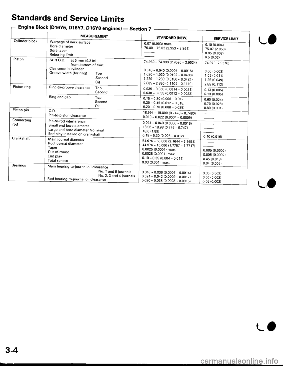
MEASUREMENT
,n7 _--
STANDAFO INEW}
0.07 10.003) max.75.00 75.02 (2.953 - 2.954)
7 4.9A0 7 4.990 t2.9520 2.95241
0.010 - 0.040 (0.0004 0.0016)1.020 - 1.030 10.0402 _ 0.0406)1.220 1.230 (0.0480 - 0.0484)2.805 - 2.820 {0.1 104 _ 0.11 tO)
0.035 - 0.060 (0.0014 0.0024)0.030 - 0.055 {0.0012 0.0022)_
0.15 0.30 {0.006 _ 0.012)0.30 - 0.45 (0.012 - 0.018)0.20 - 0.70 10.008 0.028)
18.994 - 19.000 (0.7478 _ 0.7480)0.010 - 0 0?2 lo oona -n dn^ol
SERVICE LIMIT
0.10 (0.004)
75.07 (2.956)0.05 (0.002)0.5 (0.02)
74.970 (2.9516)
0.05 (0.002)1.05 (0.041)
1.2510.049)2.85 (0.112)
0.13 {0.005)0.13 (0.005)
0.60 (0.024)
0.70 (0.028)
ljqql) _
oro to.o',ur
0.005 (0.0002)
0.005 (0.0002)
0.4510.018)0.04 (0.002)
0.05 (0.002)
0.05 {0.002)0.05 (0.002)
Cylinder blockWarpage of deck surfaceBore diameterBore taperReboring limit
Skirt O.D. at 5 mm (0.2 in)from bottom of skinClearance in cylinderGroove width {for ring) TopSecondoil
Ring to-groove clearance TopSecondRing end gapTopSecondoil
o.D.Pin-to piston clearance
Pin-to rod interferenceSmall end bore diameterLarge end bore diameter NominalEnd play installed on crankshaft
Piston
Piston ring
Piston pin
Connectingrod0.014 - 0.040 (0.0006 _ 0.ool6)18.96 - 18.98 (0.746 0.747)48.011.89)0.15 - 0.30 (0.006 - 0.012)CrankshaftMain journaldiameter
Rod iournaldiameterTaperOut of-roundEnd playTotal runout
Main bearing to-lournal o't clearance-No_ l and 5journals
_ No. 2, 3 and 4 journatsBod bearing to,journat oil ctearance
54.976 - s5.000 (2.1644 - 2.1654)44.91 6 - 45.000 1'1.17 01 _ 1.71 11 10.002510.0001) max.0.0025 (0.0001)max.
0.10 - 0.35 (0.004 0.014)0.03 (0.001) max.Bea.ings
0.018 - 0.036 (0.0007 0.0014)0.024 0.042 (0.0009 - 0.0017)0.020 - 0.038 (0.0008 _ o.oo.t5)
Standards and Service Limits
Engine Block {Dl6Y5, D16Y7, Dt6y8 enginesl - Section
L,
LO
3-4
LO
Page 50 of 2189
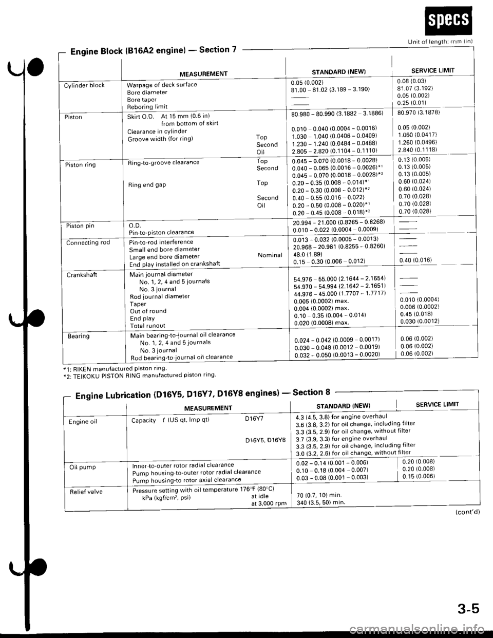
Section 7
Unlt of length: rnm ( n)
Engine Block(816A2 engine) -
MEASUREMENT
Warpage of deck surface
Bore diameterBore taperReboring limit
STANOARD {NEW)
0.05 (0.002)
8L00 81.02 (3.189 3.190)
SERVICE LIMIT
0.08 {0.03)81.07 (3.192)
0.05 (0.002)
0.25 (0.01)
Cylinder block
PistonSkin O D. At 15 mm (0.6 in)
{rom bottom of skirt
Clearance in cylinder
Groove width (for ring) ToPSecondoil
80.980 - 80.990 (3.lUUz 3. rUubl du Y/u lJ. ro/o,
I0.010 0.040 (o.ooo4 - 0.0016' 0 05 r0 002) II O3O 1.040 10.0406 - 0.04091 1 060 {0 0417) |1.230 - 1.?40 {0.0484 . 0.04881 1.260 10.04961 1'*: ?:::i?l:91'::ll:l I::::::= lPiston ringRing-to-groove clearance
Ring end gap
o.D.Pin to-piston clearance
Pin'to rod interference
Small end bore diameter
Large end bore diameterEnd play installed on crankshaft
Main journal diameterNo. 1, 2, 4 and 5 iournalsNo. 3 journal
Rod journal diameterTaperOut of roundEnd play
Total runout
Main bearing to_journal oil clearance
No. 1, 2, 4 and 5 journals
No. 3 journal
Bod bearing'to iournal oil clearance
Second
Top
Secondoil
Nominal
0.13 (0.005)
0.1310.005)0.60 (0.024)
0.60 t0.024)0.7010.028)0.70 (0.028)
,rr]q!4l
-l
u.u45 - u.u/u lu.uu ro
0.040 - 0.065 (0.0016 0.0026)*l
0.045 - 0.070 (0.0018 0.0028)*'
0.20 - 0.35 (0.008 - 0.014)*1
o.20 - 0.30 (0.008 - 0.012)*'�
0.40 0.55 (0.016 0.022)
0.20 - 0.50 (0.008 - 0.020)*'
0.20 - 0.45 (0.008 - 0.018)"
20.994 - 21.000 {0.8265 - 0.8268)
0.010 - 0.022 (0.0004 0.0009)
0.013 - 0.032 (0.0005 - 0.0013)
20.968 20.981 (0.8255 - 0.8260)
lliSlto?,o.oou o.o''r, o.rotoo'ut
Piston pin
Connecting rod
54.976 55.000 (2.1644 - 2.1654)
54.970 - 54.994 (2.1642 2.1651)
44.976 - 45.00011.'1707 - 1.1711|
0.005 (0.0002) max.0.004 (0.0002) max.0.10 0.35 (0.004 - 0.014)
0.020 (0.0008imax.
0.010 (0.0004)
0.006 (0.0002)
0.45 (0.018)
0.030 (0.0012)
Crankshaft
Eearing0.024 - 0.042 (0.0009 0.0017)
o.o3o - 0.048 {0.0012 0.0019)
0.032 - 0.050 (0.0013 - 0.0020)
0.06 (0.002)
0.06 (0.002)
0.06 (0.002)
*1: RIKEN manutactured prston rrng*2:TEIKOKU PISTON RING manufactured piston ring
gineslSection 8
(cont'd)
Engine Lubri,cation (Dl6Y5, Dl5Y7' Dl6Y8 enginesl -
MEASUREMENTSTANOARD (NEW) S€RVICE LIMIT
4.3 (4.5, 3.8)Ior engine overhaul
3.6 (3.8, 3.2) for oil change, including filter
3.3 (3.5, 2.9) for oil change, without filter
3.7 (3.9,3.3)for engine overhaul
3.3 (3.5, 2.9) for oil change, including filter
3.0 {3.2, 2.6} for oil change, without filter
0.02 - 0.14 (O.OO1 - 0.006) 0.20 {0 008)
0.10 0.18 (o.oo4 - 0.007) i 0.20 (0 008)
o 03 !.08 (qool!.oo3l _ (0 006) -
70 (0.7, 10) min.
340 (3.5,50) min
Engine oilCapacity | (US qt, lmp qt) D16Y7
D16Y5 D16Y8
lnner-to-outer rotor radial clearance
Pump housing to_outer rotor radialclearance
Pumo housrnq_to rotor a)rial clearance
Pressure setting with oil temperature 176'F (80'Ci
kPa (kgf/cm'�, PsiI at idleat 3,000 rpm
Oil pump
Relief valve
3-5
Page 123 of 2189
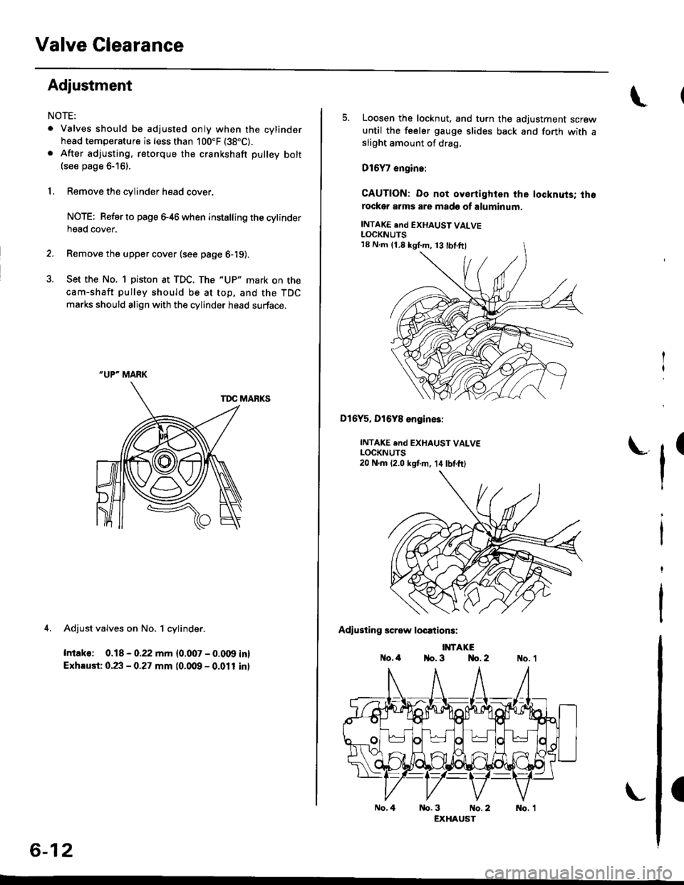
Valve Clearance
Adjustment
NOTE:
. Valves should be adjusted only when the cylindsrhead temperature is less than 100"F (38"C).
. After adjusting, retorque the crankshaft pulley bolt(see page 6-16).
1, Remove the cylinder head cover.
NOTE; Refer to page e46 when installing the cytinderhead cover.
2. Remove the upper cover (see page 6-19).
3. Set the No. 1 piston at TDC. The "UP" mark on the
cam-shaft pulley should be at top, and the TDC
marks should align with the cylinder head surface.
TDC MARKS
4. Adjust valves on No, 1 cylinder.
Intako: 0.18 - 0.22 mm {0.007 - 0.009 in}
Exhaust: 0.23 - 0.27 mm (0.009 - 0.011 inl
"UP" MARK
6-12
No.4
5. Loosen the locknut, and turn the adjustment screwuntil the feeler gauge slides back and forth with asliOht amount of drag,
D16Y7 engin.:
CAUTION: Do not oyertighlen the locknuts; thorockor arms are made of aluminum.
INTAKE end EXHAUST VALVELOCKNUTS
Dl6Y5, Dl6Y8 engin€3:
INTAKE .nd EXHAUST VALVELOCKNUTS20 N.m 12.0 kstm, 14lbtft)
Adiusting screw locations:
IMTAKEo.4 1{o. 3 No. 2
tr'
(
nb.3 No.2 No. 1EXHAUST
18 N.m (1.8 kgI.m, 13 tbl.ftl
Page 125 of 2189
Valve Seals
Replacement (Cylinder head removal not requiredl
NOTE: Cylinder head removal is not required in thisprocedure.
The procedure shown below applies when using the in-
car valve spring compressor (Snap-on YA884S withY48845 - 2 A7/8" attachment).
!@@ Alway wear approved eye protection whenusing ihe in-cai valve spring compressor.
1. Turn the crankshaft so that the No. I and the No. 4pistons are at top dead center (TDC).
2. Remove the cylinder head cover and the rocker arm
assembly.
NOTE:
. Refer to page 6-30 for rocker arm assembly
removat.
. When removing or installing the rocker armassembly, do not remove the camshaft holder
bolts. The bolts will keep the holders, springs
and rocker arms on the shaft.
. Refer to page 6-46 when installing the cylinder
head cover.
Remove the fuel injectors and the wire harness.
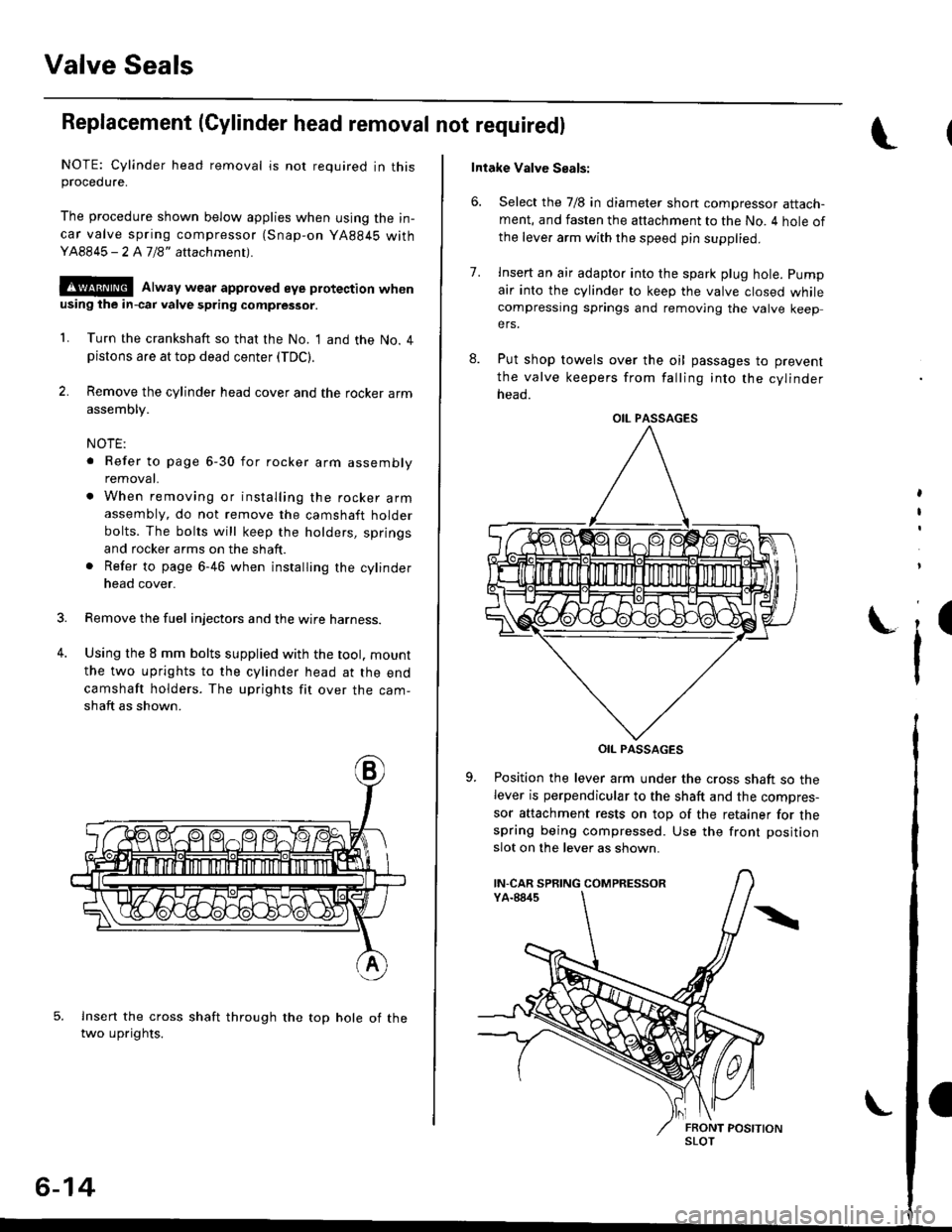
Using the 8 mm bolts supplied with the tool. mount
the two uprights to the cylinder head at the end
camshaft holders. The uprights fit over the cam-
shaft as shown.
lnsert the cross shaft through the top hole of thetwo uprights.
3.
4.
6-14
Intake Valve Seals:
6. Select the 7/8 in diameter short compressor attach-ment, and fasten the attachment to the No. 4 hole of
the leve. arm with the speed pin supplied.
8.
7.lnsert an air adapto. into the spark plug hole. pump
air into the cylinder to keep the valve closed whilecompressing springs and removing the valve keepers.
Put shop towels over the oil passages to prevent
the valve keepers from falling into the cylinder
neao.
OIL PASSAGES
Position the lever arm under the cross shaft so thelever is perpendicular to the shaft and the compres-
sor attachment rests on top of the retainer for thespring being compressed. Use the front position
slot on the lever as shown.
,
I
i'
OIL PASSAGES
IN-CAR SPRING COMPRESSOR
SLOT
Page 126 of 2189
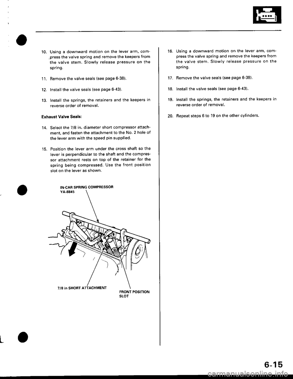
10. Using a downward motion on the lever arm, com-
.press the valve spring and remove the keepers from
the valve stem. Slowly release pressure on the
spring.
11. Remove the valve seals (see page 6-38).
12. Install the valve seals {see page 6-43).
13. Install the springs, the retainers and the keepers in
reverse order of removal.
Exhaust Valvs Sesls:
Select the 7/8 in. diameter short compressor attach-
ment, and fasten the attachment to the No. 2 hole of
the lever arm with the speed pin supplied.
Position the lever arm under the cross shaft so the
lever is perpendicular to the shaft and the compres-
sor attachment rests on top of the retainer for the
spring being compressed. Use the front position
slot on the lever as shown.
'14.
IN-CAR SPRING COMPRESSOR
7/8 in SHORT ATTACHMENT
L
16.Using a downward motion on the lever arm, com-
press the valve spring and remove the keepers from
the valve stem. Slowly release pressure on the
spnng.
Remove the valve seals {see page 6-38),
Install the valve seals (see page 6-43).
Install the springs, the retainers and the keepers in
reverse order of removal.
Repeat steps 6 to 19 on the other cylinders.
't7.
'18.
19.
20.
6-15
Page 131 of 2189
Timing Belt
Removal (cont'd)
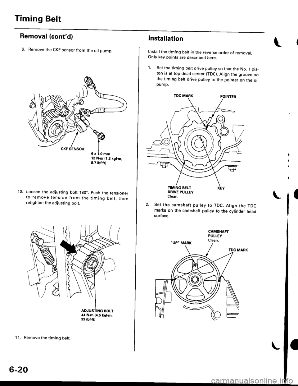
9. Remove the CKF sensor from the oI pump.
10. Loosen the adjusting bott lgO..to remove tension from theretighten the adjusting bolt.
12 N.m 11.2 kgt.m,8.7 rbf.ftl
Push the tensioner
timing be lt. then
AD.'USNNG BOLT4{ N.m 14.5 kgt m,33 tbtftl
1 1. Remove the timing belt.
6-20
lnstallation
Install the timing belt in the reverse order of removal;Only key points are described here.
l. set rhe timing belt drive pulley so that the No. 1 pis-ton as at top dead center (TDC), Align the groove onthe timing belt drive pulley to the pointer on the oilpump.
TDC MARKPOINTER
I
t
I
TIMING BELTDBIVE PULLEYClean.I
2. Set the camshaft pulley to TDC. Align the TDCmarks on the camshaft pulley to the cylinder headsurface.
Page 138 of 2189

Removal
Engine removal is not required for this procedure
!!!s@ Make sure iacks and salety stands are
f ta"eata"ea propetty and hoist brackets are attached to the
correct positions on the engine.
CAUTION:
. Use tender covels to avoid damaging painted sul-
faces.
o To avoid damage, unplug the wiling connectors
carefully while holding the connector portion to
avoid damage.
. To avoid damaging the cylinder head, wait until the
engine coolant temperature drops below 100"F
{38"C} before loossning the tetaining bolts.
NOTE:
o Mark all wiring and hoses to avoid misconnectlon
Also, be sure that they do not contact other wiring or
hoses, or interfere with other parts.
. Inspect the timing belt before removing the cylinder
h ead.
. Turnthe crankshaft pu lley so that the No. lpistonisat
top dead center (see Page 6-21)
'1. Disconnect the negative terminal from the battery'
Drain the engine coolant (see page'10-7).
a Remove the radiator cap to speed draining.
Remove the intake air duct and air cleaner housing
(see page 5 3).
Remove the mounting bolt and lock bolt. then
remove the power steering (P/S) pump belt and
pump (see page 5'5).
Loosen the idler pulley center nut and adjusting
bolt' then remove the air conditioning (A'lc) com-
pressor belt (see Page 5-6).
Loosen the mounting nut and lock bolt. then
remove the alternator belt (see page 6-19).
Remove the P/S pump bracket (see page 5-12).
3.
4.
2.
6.
1.
8. Remove the throttle cable by loosening the locknut,
then slip the cable end out of the throttle linkage
NOTE:
. Take care not to bend the cable when removing it
Always replace any kinked cable with a new one
. Adjust the throttle cable when installing (see sec-
tion 1 1).
D16Y7 engine:
Dl6Y5, Dl6Y8 engines:
THFOTTLECABLE
(cont'd)
6-27
LOCKNUT
CABLE
Page 156 of 2189

Cylinder Head
4. Apply liquid gasket (Part No. 08718 - 0001 or 08718 -
0003) to the head mating surfaces of the No. 1 and
No.5 camshaft holders.- Apply liquid gasket to the shaded areas
Set the rocker arm assemblY in place and loosely
installthe bolts.- Make sure that the rocker arms are properly posi-
tioned on the valve stems.
Tighten each bolt two turns at a time in the sequence
shown below to ensure that the rockers do not bind
on the valves.
Specitied torquo:
8 mm bolts: 20 N.m (2.0 kgt'm, l/t lbf'ft)
Apply engine oil to the threads.
6 mm bolts: 12 N.m {1.2 kgif'm, 8.7 lbf'ft)
Apply engine oil to the thresds.
6 mm bolts: O, @. @, @
7. Install the back cover. then install the camshaft pul-!
6-45
lnstallation
lnstallthe cylinder head in the reverse order of removal:
NOTE:
. Always use a new head gasket.
. Cylinder head and cylinder block surface must be
clean.
. "UP" mark on the camshaft pulley should be at the top
. Turn the crankshaft so the No. 1 piston is at TDC (see
page 6-20).
. Clean the oil control orifice before installing.
a Do not use the upper cover and lower cover to store
removeo rlems.
Clean the upper cover and lower cover before instal-
taUon.
Cylinder head dowel pins must be aligned.1.
CYUNOER HEAD
PINS
(cont'd)