Page 1239 of 2189
\L
lJ\
\flREAR CHANNEL N\
\,\
\
\i\Ill
ld 1l
6P lll
REo" c"AN"..: | 1lcoLLAR J I
)€)\IJ
6/
\3-
REGULATORHANOLE
:& fr\
r lll'All criss lLl
l'A sroeeen lll
W-*d
t a)" u\
*)u*ro* \
Repracement, pase 20 ,tt
l5[1tfCHANNEL
OUTER HANDLEReplacement, Page 20-11
STRIKERAdjustment,page 20'23
I
I
%grc
POWER WINDOWMOTOR
LOCK RODPROTECTOR
LATCHPROTECTORReplacement,page 20-12
POWER OOORLOCK ACTUATOE
t
20-9
Page 1243 of 2189

t}
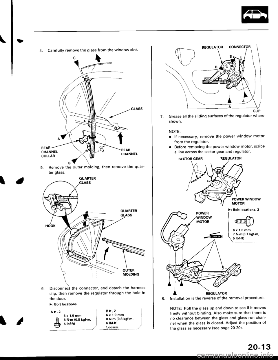
4. Carefully remove the glass from the window slot.
c\
REARCHANNELCOLLAR
Remove the outer molding, then
Ier grass.
remove the quar-5.
\
6. Disconnect the connector, and detach the harness
clip, then remove the regulator through the hole in
the door.
>: Bolt locataons
A>,2 ]6x1.0mm L
[l o t't.- to.a rsl -. j
fr e ttt ttt )---�.---.-,/
B >,26 x 'l.0 mmI N.m {0.8 ksl'm,6 tbf.ft)
I
)
OUARTER
20-13
7.
CLIP
Grease all the sliding surfaces of the regulator where
shown.
NOTE:
a lf necessary, remove the power window motor
from the regulator.
. Before removing the power window motor, scrloe
a line across the sector gear and regulator.
SECTOR GEARREGULATOR
POWER WINDOWMOTOR
>: Bolt locations,3POWERwTNDOWMOTOR
l'
-... er
A nicuuron
8. lnstallation is the reverse of the removal procedure.
NOTE: Rollthe glass up and down to see if it moves
freely without binding. Also make sure that there is
no clearance between the glass and glass run chan-
nel when the glass is closed. Adjust the position of
the glass as necessary (see page 20-20).
Page 1250 of 2189

Doors
Glass/Regulator Replacement (cont'dl
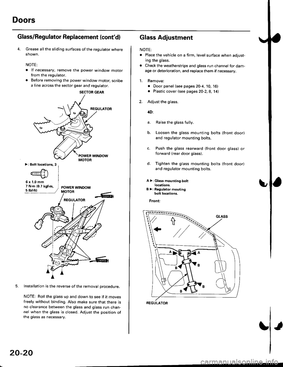
Grease all the sliding surfaces of the regulator where
shown.
NOTE:
. lf necessary, remove the power window motorfrom the regulator.
. Before removing the power window motor, scribe
a line across the sector gear and regulator.
REGULATOR
5. Installation is the reverse of the removal orocedure.
NOTE: Roll the glass up and down to see if it moves
freely without binding. Also make sure that there isno clearance between the glass and glass run chan-nel when the glass is closed. Adjust the position ofthe glass as necessary.
SECTOR GEAR
20-20
Glass Adjustment
NOTE:
. Place the vehicle on a firm, level surface when adjust-
ing the glass.
. Check the weatherstrips and glass run channel for dam-
age or deterioration, and replace them if necessary.
1. Remove:
. Door panel (see pages 20-4, 10, 16). Plastic cover (see pages 20-2,8, 14)
2. Adjust the glass.
4D:
Raise the glass fully.
Loosen the glass mounting bolts (front door)
and regulator mounting bolts.
Push the glass rearward (front door glass) or
iorward (rear door glass).
Tighten the glass mounting bolts (front door)
and regulator mounting bolts.
A >: Gl.3s mounting boltlocations.B >: Regulrtor moutingbolt loc.tions.
Front:
a.
b.
d.
REGULATOR
Page 1337 of 2189
Opener Cable/Opener and Latch/Wiper and Washer
Component Location Index
2Dt3DItD'
y"Tl,"nll,ib?*'r.* o*t"
Replacement, Page 20_1 13
Adiustment, Page 20'1 17
WINDSHIELDWASHER NOZZLESAdjustment, Page 20_1 17
HOOD LATCH
{see page 20-110)
REAR WINDOW WIPER
ARM and MOTORReplacement, Page 20-1 15
Adjustment, page 20 117
LOCK CYLINDER(see page 20 113)
LOCK CYLINDER
TRUNK LIO LATCH
{see page 20 112)
FUEL LID OPENERCABLE(see page 20-108i
LID OPENERCABLE(see page 20 108)
LID/FUELLID OPENER(see page 20 111)
RELEASE HANDLE(see page 20-110)
3D:
REAR WINDOWWASHER NOZZLEAdiustment, page 20-1 17
REAR WINDOWWASHER TUBE(see page 20-116)
HATCH OPENERCABLE(see page 20 110)
WASHER RESERVOIRReplacement, Page 20-1 15
HATCH/FUEL LID OPENER(see page 20 1'11)
FUEL LID OPENERCABLE(see page 20 110)
(see page 20 111)
20-107
Page 1345 of 2189

Rear Window Wiper
Arm and MotorWasher Reservoir
Replacement
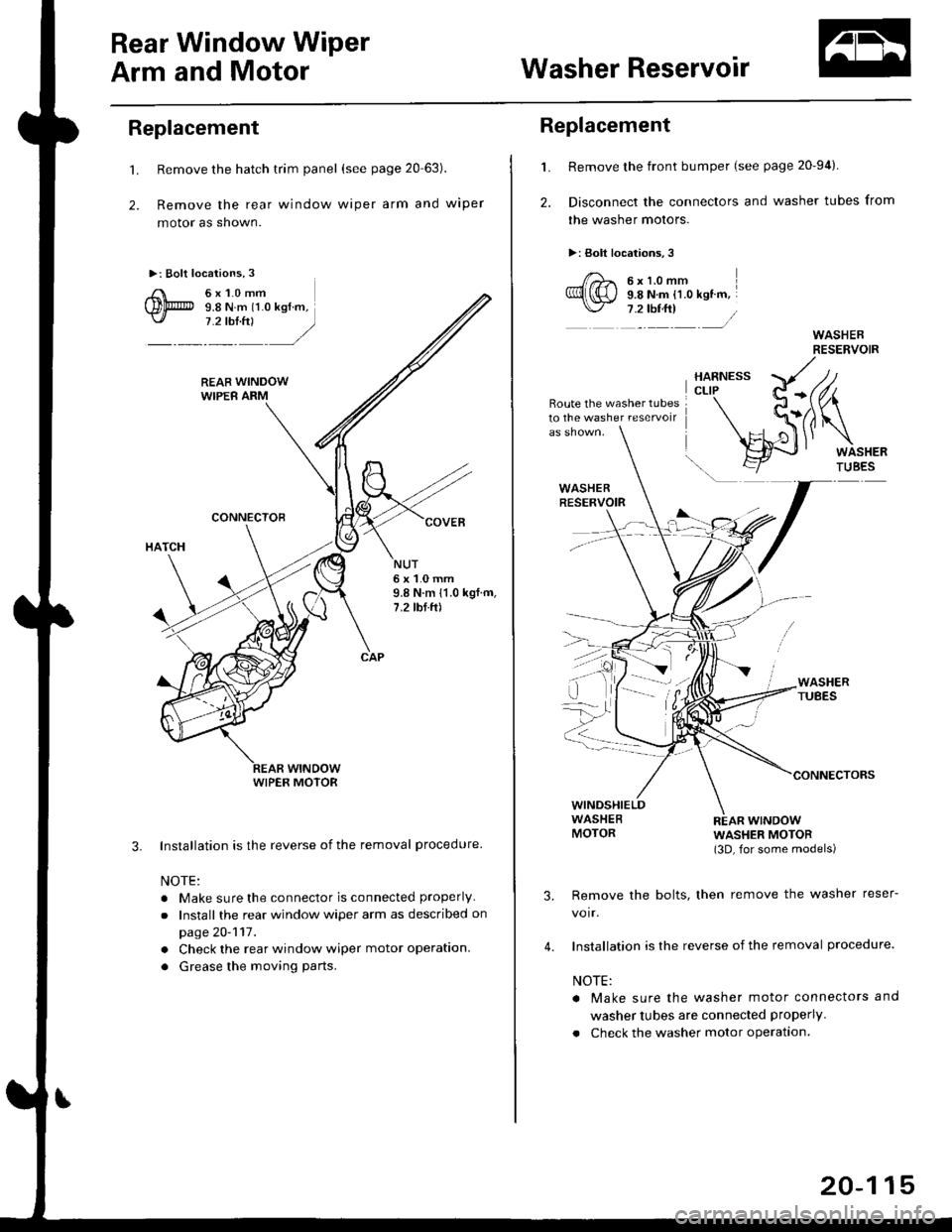
't.
2.
Remove the hatch trim panel (see page 20 63).
Remove the rear window wiper arm and wiper
motor as shown.
Installation is the reverse of the removal procedure
NOTE:
. Make sure the connector is connected properly
.Install the rear window wiper arm as described on
page 20-117.
. Check the rear window wiper motor operation.
. Grease the moving parts.
3.
NUT6x1.0mm9.8 N.m 11.0 kgf.m,7.2 tbf.ft)
WIPER MOTOR
L
2.
Replacement
Remove the front bumper (see page 20-94).
Disconnect the connectors and washer tubes from
the washer motors.
>: Bolt locations,3
/)^ 6xt.omm
Ql(S) s.e ru.- tt.o ret '".\./ 7 .2 tbf.ft) /
Route the washer tubes10 the washe. reservoir
wtNDowWASHER MOTOR(3D, for some models)
Remove the bolts, then remove the washer reser-
voir.
Installation is the reverse of the removal procedure.
NOTE:
a Make sure the washer motor connectors and
washer tubes are connected properly.
. Check the washer motor operation.
3.
4.
20-115
Page 1359 of 2189
Washer Tube
Replacement (cont'dl
NOTE: To remove the rear window washer tube (3D), remove the following parts from the left side of the vehicle.
- Inner fender (see page 20-'106)- Kick panel and side trim (see page 20-60)- Rear seat-back and rear seat cushion (see page 20-80)- Spare tire lid- Rear center shelf and rear side shelf (see page 20-60)- Rear trim panel and side trim panel (see page 20-60)- Ouarter trim panel (see page 20-60)- Rear roof trim (see page 20-65)- Hatch spoiler (see page 20-1011
>: Washer nozzle, clip and cushion locationsA >.9 B>,2 C>, 1
I sl -..._, 1
aj\
_ ____/ _>_t _ _/
(see page 20 101).
REAR WINDOWWASHER TUBE(for some models)
Installation is the reverse ofthe removal procedure.
NOTE:
. Take care not to pinch the washer tubes.
. lf necessary, replace any damaged clips.
. After installing, adjustthe aim ofthe washer nozzles (see page2O-1111.
motor.
20-130
Page 1377 of 2189
'99 - 00 Models
SRS components are located in this area, Review the SRS component locations, precautions, and procedures in the SRS
section (24) betore perfoming repairs or service.
HEATER UNITReplacement, page 21'39
Overhaul, page 21-41
BLOWEB UNITReplacement, page 21-37Overhaul, page 21 38
HEATER FANswtTcH
RECIRCULATIONCONTROL MOTORTest, page 21-48Beplacement, page 21-48
AIR MIX CONTROL MOTOBTest, page 21-46Replacement, page 21 46
BLOWERTest, page 21-49
POWER TRANSISTORTest, page 21 50
HIGH RELAY
MODE CONTROLDIALHEATER VALVE CABLEAdjustment, page 21 45TEMPERATURE CONTROLDIALAdjustment, page 21-45
REAR WINDOWDEFOGGERswtrcHSee section 23MODEMOTORTest, page 21 47Replacement, page 2 l-47A/C SWTTCH
lwith A/cl
CONTROL SWITCH
21-3
Page 1410 of 2189

Troubleshooting -'99 - 00 Models
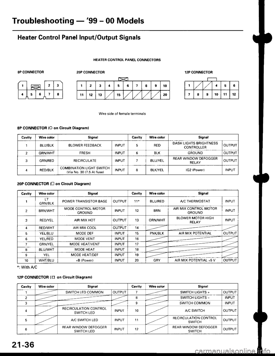
Heater Control Panel Input/Output Signals
HEATER CONTROL PANEL CONNECTORS
8P CONNECTOR2OP CONNECTOR12P CONNECTOR
Wire side of female terminals
8P CONNECTOR (O qn Circuit Diagram)
20P CONNECTOR {D on circuit Diagram}
*: with Ay'c
12P CONNECTOR (tr on Circuit Diagraml
CavityWire colorSignalCavilyWhe colorSignal
BLU/8LKBLOWER FEEDBACKINPUT5REDDASH LIGHTS BRIGHTNESSCONTROLLEROUTPUT
2GRN/lVHTFRESHINPUT6BLKGBOU N DOUTPUT
3GRN/REDRECIRCULATEINPUT7BLU/YELREAR WINDOW DEFOGGERRELAYOUTPUT
4RED/BLKCOMBINATION LIGHT SWITCH(Via No. 30 (7.5 A) fuse)INPUT88LfiELlG2 {Power)INPUT
CavityWire colorSignalCavityWire colorSignal
LTGRN/BLKPOWER TRANSISTOR EASEOUTPUT't1BLU/REDAy'C THERMOSTATINPUT
2BRNMHTMODE CONTROL MOTORGROUNDINPUT12BRNAIR MIX CONTROL MOTORGROU NDINPUT
3RE D/YELAIR MIX HOTOUTPUT13ORNAA/HTBLOWER MOTOR HIGHRELAYINPUT
RED,ryvHIAIR MIX COOLOUTPUT14
5YEUBLUMODE DEFINPUTPN K,/BLKAIR MIX POTENTIALOUTPUT
6YEUREDMODE VENTINPUT16
7GRNI/ELMODE HEAT/r'ENTINPUT11
IBLUAVHTMODE HEATINPUT18
9YELMODE HEAT/DEFINPUT19
10WHT/BLU+B (Power)INPUT20GRYAIR MIX POTENTIAL +5 VOUTPUT
CavityWilecolorSignalCavityWi.e cololSignal
lSWITCH LED COMMONOUTPUT1SWITCH LIGHTS +OUTPUT
2ISWITCH LIGHTS -INPUT
39SWITCH COMMONINPUT
4RECIRCULATION CONTROLSWITCH LEDINPUT10A,/C SWITCHOUTPUT
5A./C SWITCH LEDINPUT11RECIRCULATION CONTROLSWITCHOUTPUT
6REAR WINDOW DEFOGGERSWITCH LEDINPUT12REAR WINDOW DEFOGGEBSWITCHOUTPUT
21-36